Launch Facility & Pad Construction
Concrete, steel and water engineered to survive a rocket motor at arm's length — flame trenches, deluge systems, cryogenic farms and lightning masts, built for the ten most violent seconds in construction.
Last updated 2026-07-28 by the BuildPedia Editorial Team.
What is Launch Facility & Pad Construction?
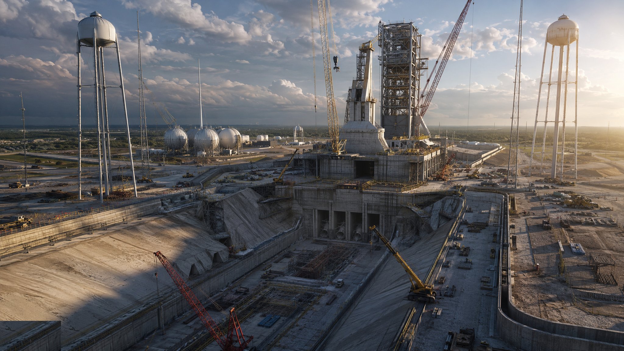
A launch pad is industrial plant subjected, deliberately, to conditions no other structure tolerates: a rocket motor's full thrust and exhaust plume metres away, acoustic levels that can shake hardware apart, and propellant loads that range from kerosene to liquid hydrogen. The centrepiece is the pad deck and flame trench — the channel beneath the mount that turns the exhaust sideways and out. Trench floors and walls are built in refractory concrete — high-alumina cement mixes (the Fondag-type materials the industry standardised on) placed in massive, joint-controlled sections — and clad where the plume bites hardest with refractory brick or steel plate, because ordinary concrete spalls, steams and fails at exhaust temperatures. Every surface is designed to be eroded, inspected and repaired: a pad is a consumable structure with a maintenance budget, not a monument.
The systems wrapped round the pad are process engineering on a civil scale. The deluge — hundreds of thousands of litres of water dumped in seconds — does two jobs: cooling the steel and concrete, and suppressing the acoustic energy that would otherwise reflect back into the vehicle. Propellant farms sit at regulated separation: LOX spheres and tanks with their vapour management, liquid hydrogen spheres — vacuum-jacketed, with the largest LH2 spheres ever built sitting at Cape Canaveral — kerosene or RP-1 farms, methane systems on the newer pads, all connected by vacuum-jacketed or insulated transfer lines to the pad, with valve pits, purges, flare stacks and gas detection throughout. And over it all, lightning protection: masts and catenary wire systems designed to take the strike the rocket would otherwise take, bonded into an earth network engineered to keep strike currents away from propellant and electronics.
The supporting cast is equally specialist. Integration buildings — vertical or horizontal assembly halls where vehicle stages are mated — need high-bay cranes, clean environments and door openings the size of the building's gable. Transporter routes — crawlerways, rail lines or heavy-haul roads from integration building to pad — are pavements designed for wheel loads and rolling weights that make motorway construction look delicate, with gradients held to a percent or two because a moving rocket does not like hills. Control and blast-hardened facilities, camera and instrumentation mounts, and the security fencing of a licensed spaceport complete the site. In the UK, vertical launch sites operate under the Space Industry Act 2018 and CAA spaceport licensing; in the Gulf and elsewhere, range safety and environmental consents shape the layout the same way.
When and why is Launch Facility & Pad Construction used?
Launch facility construction applies to orbital and suborbital spaceports, sounding-rocket ranges, engine test stands and the reusable-vehicle landing pads that increasingly accompany them. The heavy civil phase — trench, pad deck, propellant farms, routes — leads the programme because everything else mounts on it, and commissioning of deluge and propellant systems runs long after the concrete is cured. It matters because the failure modes are catastrophic and public: a flame trench that spalls, a deluge that under-delivers or a propellant system that leaks is not a snag list, it is a lost vehicle or a lost licence. The design margins are therefore set by the vehicle, not by convention — the pad is built around a specific rocket's thrust, plume and propellants — and construction quality is verified by full-scale water and flow testing before any vehicle is risked. Durability engineering is equally central: chlorides, thermal cycling and impingement erosion mean refractory placement, curing and joint details are controlled like nuclear work.
Types of Launch Facility & Pad Construction
Vertical launch pads with flame trenches
The classic orbital pad: elevated mount over an open flame trench with deflector, refractory-lined and deluged, surrounded by propellant farms, lightning masts and service masts or towers. Geometry is vehicle-specific; the trench is the consumable heart.
Flat-pad and deflector pads
The mount sits on a flat deck with the plume turned by a water-cooled or refractory deflector beneath it — the modern pattern for vehicles with landing legs and rapid reflight ambitions. Less civil mass, more precision steelwork and water engineering.
Engine and stage test stands
Static-fire facilities: heavily anchored thrust frames taking the full motor load into ground, flame ducts or buckets, deluge and propellant systems identical in kind to a launch pad — but built to fire weekly, so erosion rates and inspectability drive every detail.
Horizontal launch and spaceplane infrastructure
Runways and aprons for air-launch and spaceplane operations — heavy-duty pavements, fuel farms, integration hangars and the exclusion zones of a licensed spaceport, closer in kind to airport construction but with propellant and range-safety overlays.
Launch Facility & Pad Construction: step by step
Step 1: Earthworks, foundations and thrust-rated anchorage
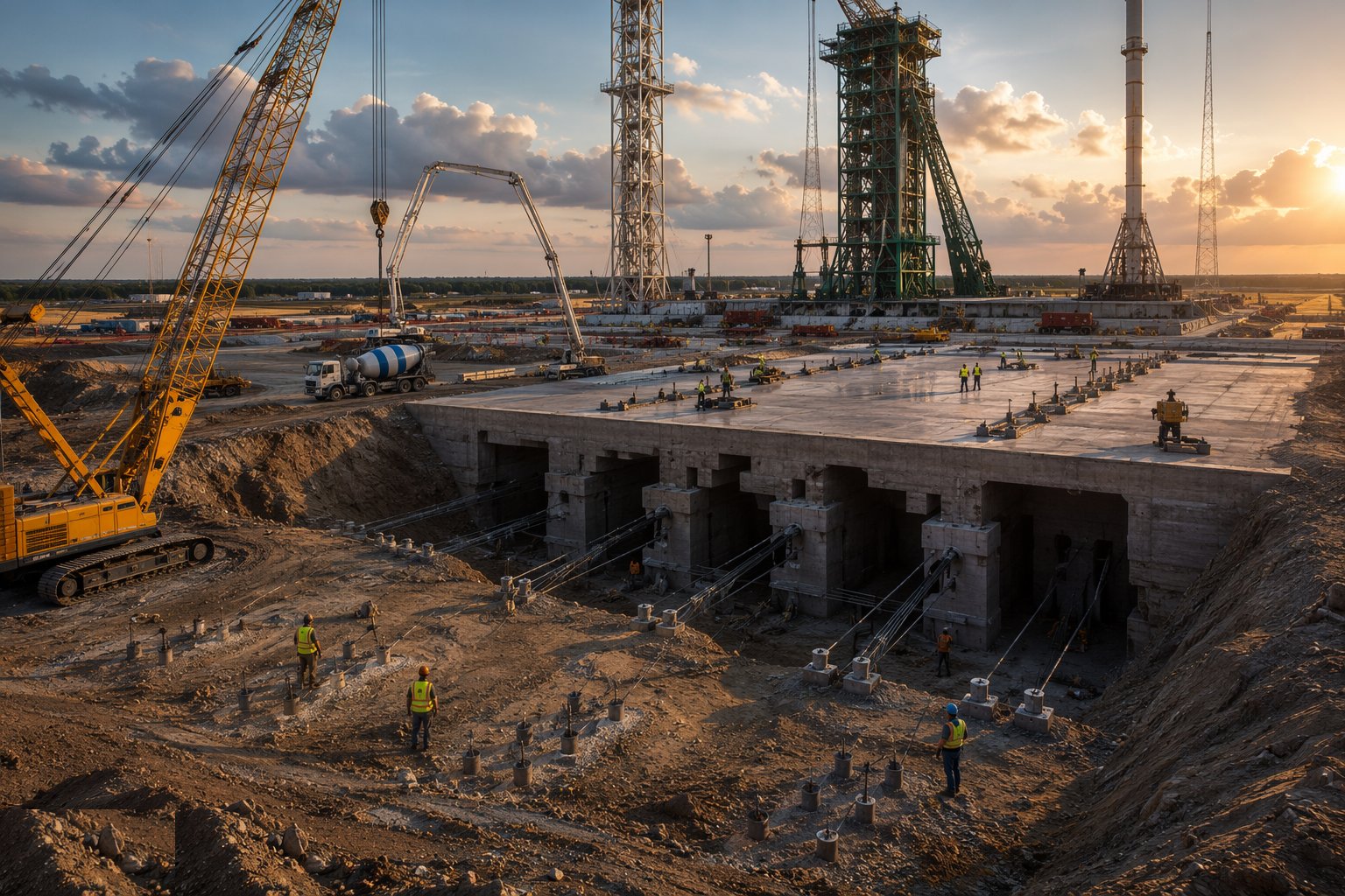
Pad structures are founded for loads that run in both directions: the static weight of vehicle and mount, and the dynamic hammer of ignition. Excavation for the flame trench is a major dig in its own right — deep, battered or sheeted, dewatered where the water table intrudes — and the hold-down and anchor systems for the mount are cast into massive reinforced foundations with anchor positions surveyed to millimetres, because the vehicle interface forgives nothing. Settlement criteria are tighter than any industrial norm: a pad that tilts is a launch azimuth problem.
Step 2: Construct the flame trench and refractory lining
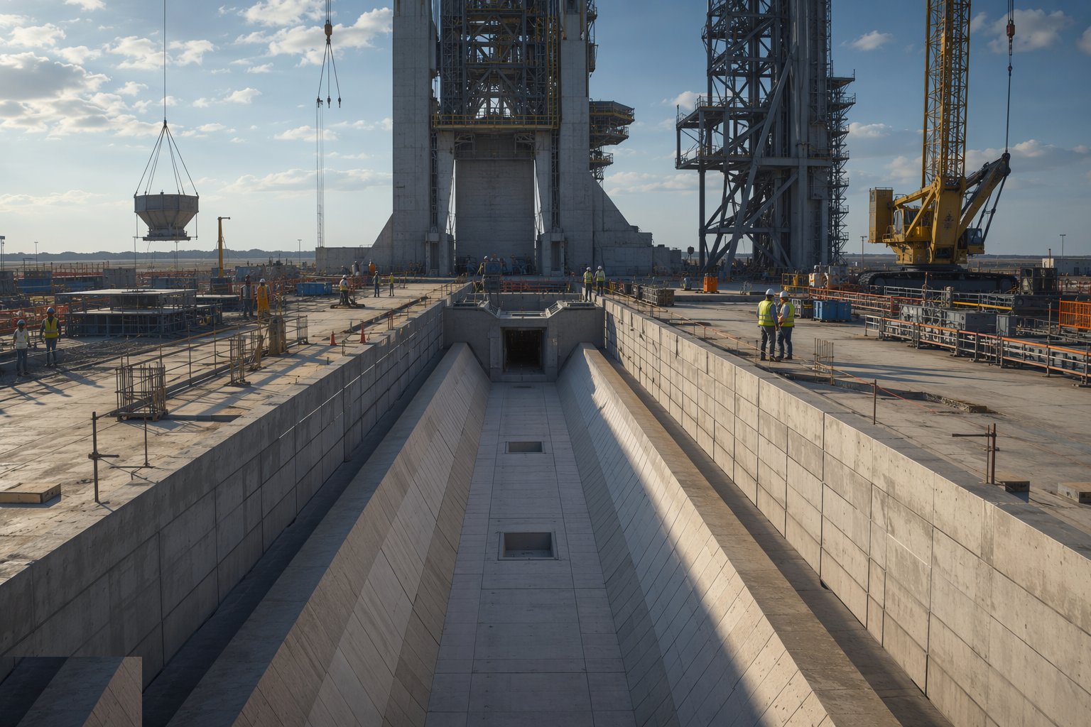
The trench is built in refractory concrete placed in controlled monolithic sections — high-alumina cement mixes batched, placed and cured to the supplier's regime, with water curing and temperature control enforced because refractory hydration is as unforgiving as mass concrete, in reverse. Construction joints are minimised and detailed against the plume flow; where brick or plate lining is specified, it is laid or fixed to fall away cleanly for replacement. Every pour is documented — batch temperatures, cure records, test specimens — because the trench will be inspected after every launch and its as-built file is the baseline for the erosion surveys.
Step 3: Install the deluge and water suppression system
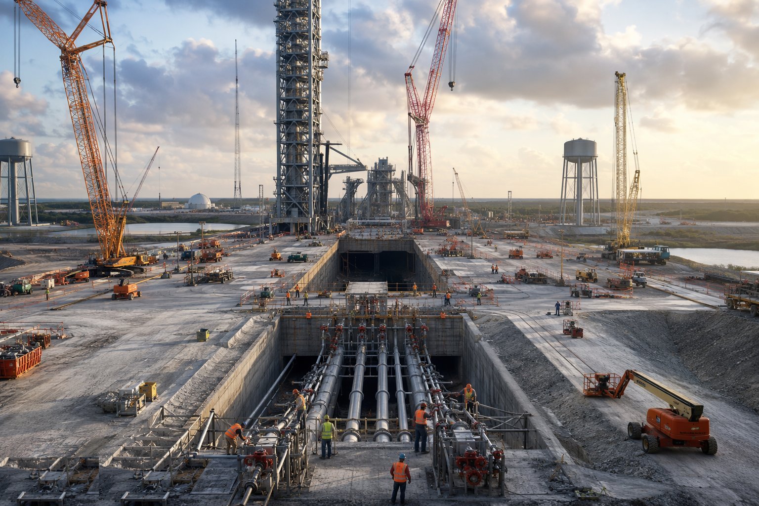
Water towers or impoundments, massive mains, valve systems and the deck nozzles and rain-birds go in as one engineered system, then are proven by full-scale flow tests: the deluge is fired with nothing at stake but water, and flow rates, coverage and timing are measured against the design. These tests are events — hundreds of thousands of litres in seconds — and they are filmed, instrumented and repeated until the numbers match, because the first deluge that matters happens under a live rocket.
Step 4: Build propellant farms and transfer systems
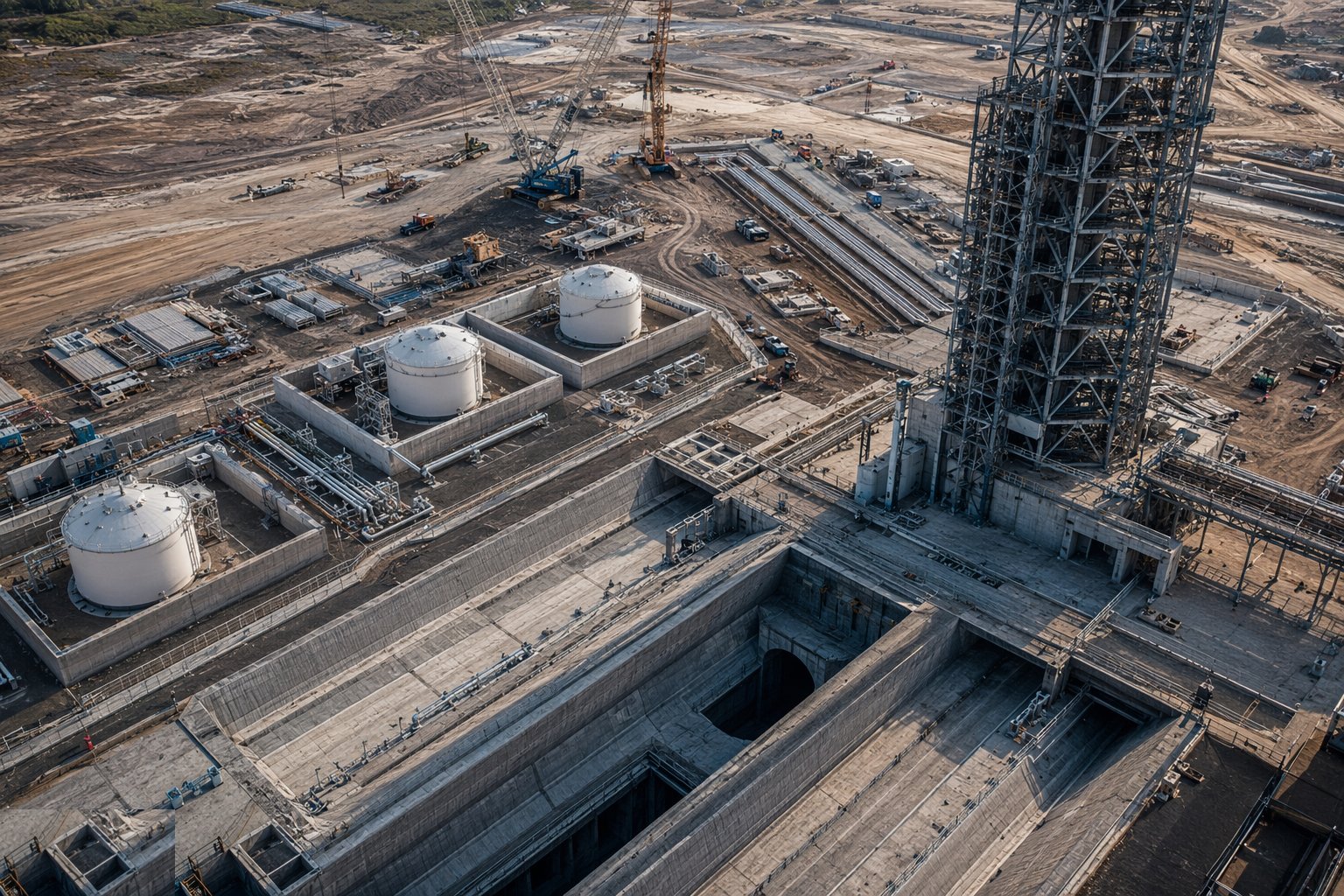
Spheres, tanks and their bunds are set at the consented separation distances; vacuum-jacketed and insulated lines are welded, purged and tested run by run — X-ray and dye-penetrant on the cryo lines, pressure and leak testing to the process codes, cleanliness verified for oxygen service where a smear of grease is an ignition source. Valve pits, flare stacks, gas detection and purge systems complete the farm, and the whole installation is commissioned progressively: inert gas first, then cryogens, with every first-fill procedure rehearsed and monitored.
Step 5: Erect lightning protection and the earth network
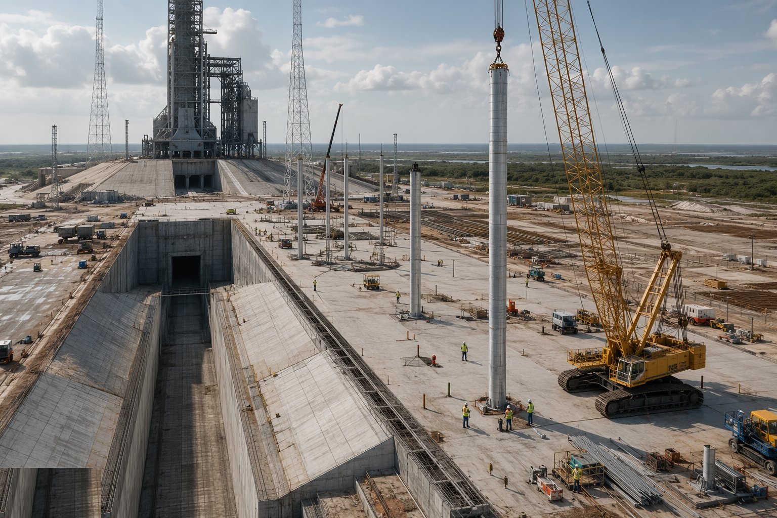
Masts or towers are piled, founded and erected around the pad, catenary wires tensioned between them, and the whole system bonded into an earth electrode network tested for the resistance and bonding continuity the design demands. The point is routing: strike current must prefer the masts and wires, and find a path to ground that never threads the propellant systems or the instrumentation. Rolling-sphere protection studies are checked against the as-built geometry, not just the drawings.
Step 6: Construct integration buildings and transporter routes
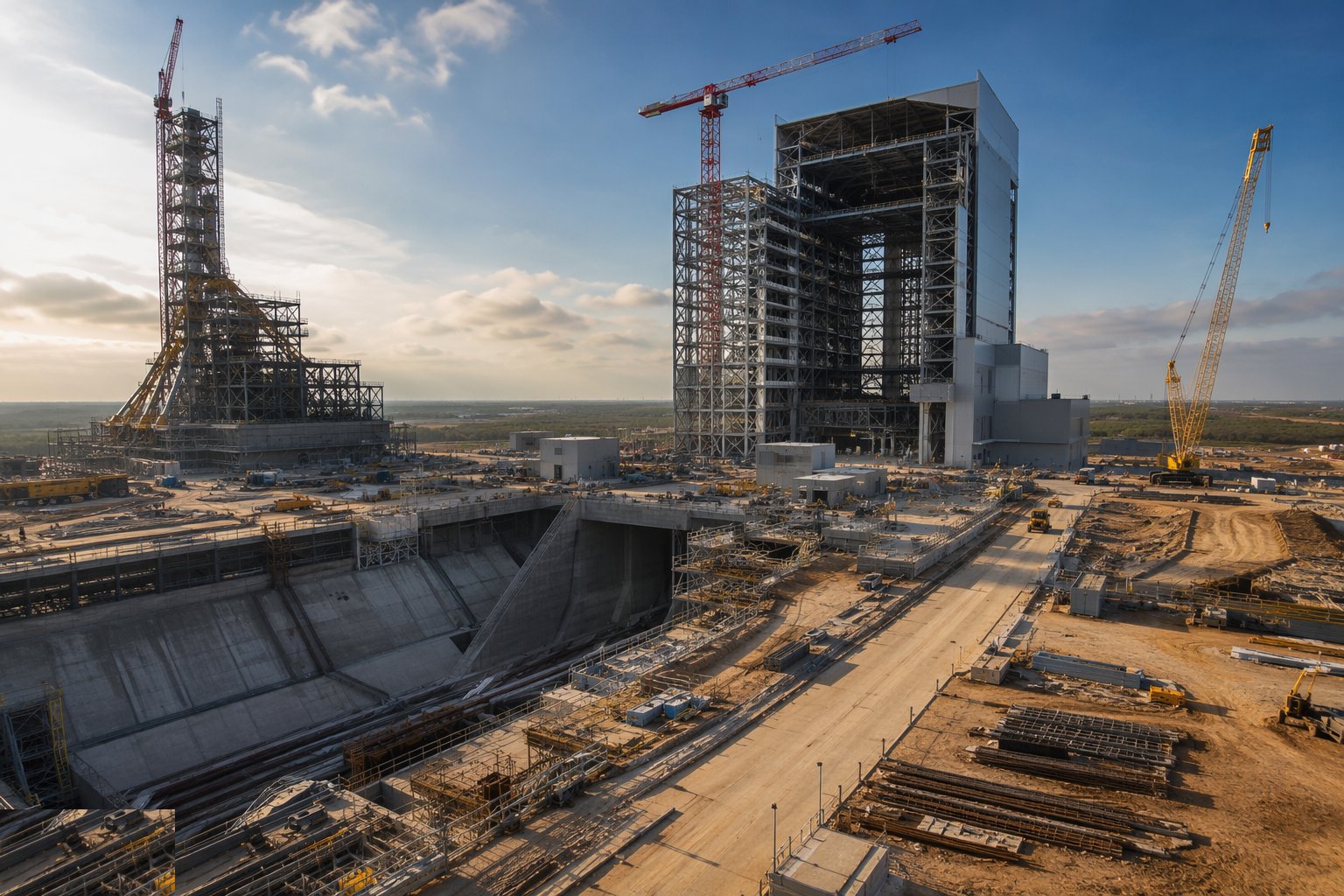
The assembly hall rises as a high-bay steel structure with its cranes — runway beams surveyed true, crane load-tested — and its doors and environmental controls commissioned before vehicle hardware arrives. Transporter routes are paved for extraordinary loads: thick reinforced concrete or heavy flexible pavement on engineered subgrade, gradients and cross-falls held to the vehicle transport spec, turning areas and crossings load-verified. The route is then proven with ballasted test runs before it ever carries a stage.
Step 7: Commission, test and license the facility
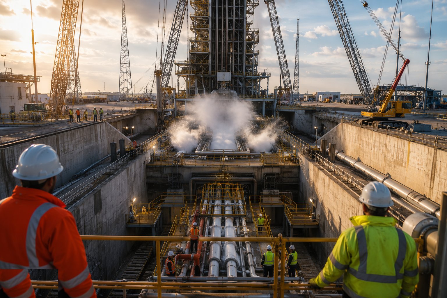
The facility is handed over through integrated testing: deluge firings, propellant flow rehearsals with inert stand-ins, emergency shutdown demonstrations, instrumentation and camera systems checked against the data specification. Documentation — refractory batch records, weld and NDT files, leak test certificates, earth network results — feeds the safety case behind the spaceport or range licence. The pad is then maintained like plant: post-test inspections, erosion surveys, refractory repairs, because the facility is only ever between launches.
Plant and equipment
- Refractory concrete batching, placement and curing equipment for high-alumina mixes
- Mass excavation and piling plant for trench and thrust foundations
- Deluge pumps, water towers/impoundments and large-bore valved mains
- Cryogenic storage spheres/tanks, vacuum-jacketed pipework and orbital welding sets
- Lightning masts, catenary tensioning equipment and earth resistance testers
- Heavy crawler or multi-axle transporters for route proving and vehicle rollout
- High-bay overhead cranes for integration buildings, with load-test weights
- Flow metering, high-speed instrumentation and acoustic/vibration monitoring for commissioning tests
Quality control checks
- Refractory concrete batch, placement and cure records per section, with test specimens
- Anchor and hold-down as-built surveys against the vehicle interface tolerances
- Cryogenic and propellant line weld NDT, pressure and leak test certificates, cleanliness records for oxygen service
- Full-scale deluge flow test results against the design envelope
- Earth network resistance and bonding continuity measurements, as-built
- Pavement and route load verification, gradient surveys and ballasted test-run records
Safety considerations
- Cryogenic first-fills and commissioning under rehearsed procedures with exclusion zones and oxygen monitoring
- Hydrogen and fuel farm work: gas-free certification, hot-work permits, anti-static and bonding discipline
- Deep trench excavation: support, access and dewatering controls through construction
- Heavy lifts of masts, spheres and cranes: engineered lifting plans, no improvisation at radius
- Full-scale water and flow testing: exclusion zones sized for the event, communications rehearsed
- Energised vehicle-support systems: lockout and permit regimes once propellant and pyrotechnic-capable systems go live
Common defects
- Refractory spalling from poor cure control or joint details — discovered at the first hot fire, repaired between campaigns
- Deluge coverage gaps and pressure shortfalls found at flow test, forcing nozzle and main redesign
- Cryogenic line leaks at welded joints and valve seats, traceable to skipped NDT or contaminated oxygen lines
- Anchor groups out of tolerance, turning mount installation into a machining-and-grouting exercise
- Lightning protection bonding gaps — as-built geometry that never matched the rolling-sphere study
- Route pavements rutting or cracking under ballasted test runs: subgrade or thickness value-engineered
Best suited for
- Orbital and suborbital spaceports and licensed vertical launch sites
- Engine and stage static-fire test facilities
- Reusable vehicle landing and recovery pads
- Air-launch and spaceplane ground infrastructure
How long does Launch Facility & Pad Construction take?
Typical duration: A full vertical launch complex runs 24–48 months from enabling works to licensed readiness; the pad, trench and propellant core alone typically occupies 18–30 months, with integrated commissioning adding 6 months of testing..