District Heating & Cooling Networks
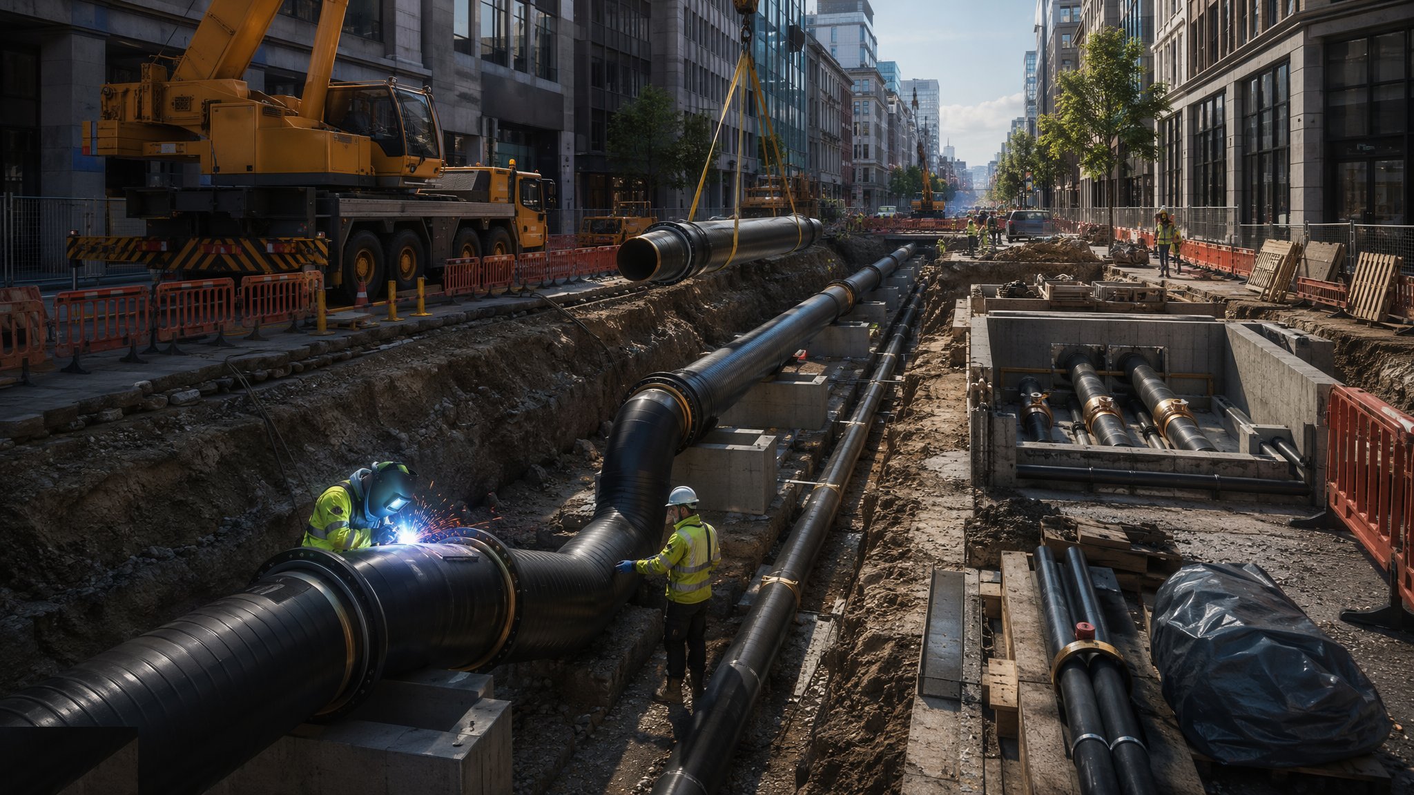
Mains of pre-insulated bonded pipe welded end to end through live streets, carrying hot or chilled water under the city — a heat network that only works if every joint, anchor and expansion loop is exactly where the design put it.
Last updated 2026-07-28 by the BuildPedia Editorial Team.
What is District Heating & Cooling Networks?
A district heating or cooling network is a factory pipe rack buried in the public highway. The pipe of choice is a pre-insulated bonded system: a steel (or, on smaller low-temperature networks, polymer) carrier pipe wrapped in rigid polyurethane foam inside an HDPE casing, manufactured to the EN 253 family of standards, with copper alarm wires embedded in the foam to report moisture ingress before it becomes a corrosion crater. Pipes arrive in 6–16 m sticks and are welded end to end; at every field joint the insulation is made good with a site casing and injected foam so the finished main is one continuous insulated tube. Heating networks run flow and return at anywhere from 50 °C low-temperature schemes up to 110 °C-plus legacy systems; Gulf district cooling runs chilled water at 4–6 °C supply in pipes that can exceed a metre in diameter on the primary mains.
The buried main is a structural system, not just plumbing. Hot pipe expands — a 100 m run of steel at 90 °C grows by the best part of 100 mm — and bonded pre-insulated pipe is designed to be restrained by soil friction so the stress is taken in the pipe wall, with expansion loops, L-bends and Z-bends at the few places movement is allowed, and anchor blocks where the design says movement stops. Get the restraint wrong — soft backfill, a loop cut out because it was in the way, an anchor cast in the wrong chamber — and the pipe finds its own weak point, usually at a weld, usually at 2 a.m. in winter. Valves, vents and drains live in chambers or building entries, and the whole network is flushed, pressure-tested and continuously monitored on the alarm wires before a litre of heat is sold.
The construction environment is the hard part. These mains live in live streets: in the UK, street works under NRSWA with notices, permits, Chapter 8 traffic management and SROH reinstatement hanging over every trench; trial holes ahead of the dig because the corridor is shared with 132 kV cables, gas mains and someone else's fibre. Trench depth runs 0.75–1.5 m typically, deeper at crossings, with the pipe bedded and surrounded in compacted sand to the manufacturer's spec — the surround is structural, because soil friction is what restrains expansion. In the Gulf the chilled-water networks of the district cooling providers (Empower and Emicool in Dubai, Tabreed in Abu Dhabi) go in with development infrastructure or as retrofits through existing streets, with municipality and RTA NOCs, high water tables on coastal corridors, and summer ground temperatures that make the thermal design and the pipe handling their own problems.
When and why is District Heating & Cooling Networks used?
Network laying follows the energy centre and runs ahead of customer connections, because the pipe in the street is the asset everything else hangs off. District heating is chosen where a heat source — energy-from-waste, CHP, large heat pumps — can beat individual boilers on carbon and cost across a dense load; district cooling is the Gulf default because one central chiller plant with thermal storage beats a thousand split units on efficiency, roof space and peak electrical demand. The route method is decided by the street: open cut where the highway authority grants it, thrust boring or directional drilling where it will not. Bonded pre-insulated pipe is specified because it is monitorable (the alarm wires), durable (50-year design life claims rest on the foam staying dry) and restraint-compatible with buried expansion design. Value-engineer the joint insulation, the surround or the testing and you build a leak-detection business instead of a heat network.
Types of District Heating & Cooling Networks
Bonded steel pre-insulated mains
Steel carrier pipe, PUR foam and HDPE casing to EN 253, welded joints, site-foamed joint casings and embedded alarm wires. The standard for primary and secondary heating and chilled-water mains: high temperature capability, full restraint design, and a leak-detection nervous system built in.
Flexible polymer pre-insulated pipe
Cross-linked polyethylene (PEX) carrier pipe in coils or long sticks, for low-temperature (fourth-generation) heat networks and tertiary connections. Fewer joints, faster laying, snakes around obstacles — but capped at lower temperatures and pressures, and the fittings become the critical detail.
Twin-pipe systems
Flow and return carriers in one casing, halving trench width in congested corridors. Standard on smaller heating branches; the thermal interaction between flow and return is accounted for in the design, and site joints need both carriers welded before the shared casing is foamed.
Tunnel, rack and bridge-mounted pipework
Networks carried in service tunnels, on surface racks or across bridges where burial is refused or impractical. Exposed runs mean conventional lagging, expansion loops in plain sight, and support steelwork taking thermal forces — easier to inspect, harder on the planning officer's eye.
District Heating & Cooling Networks: step by step
Step 1: Prove the route and set up the street works
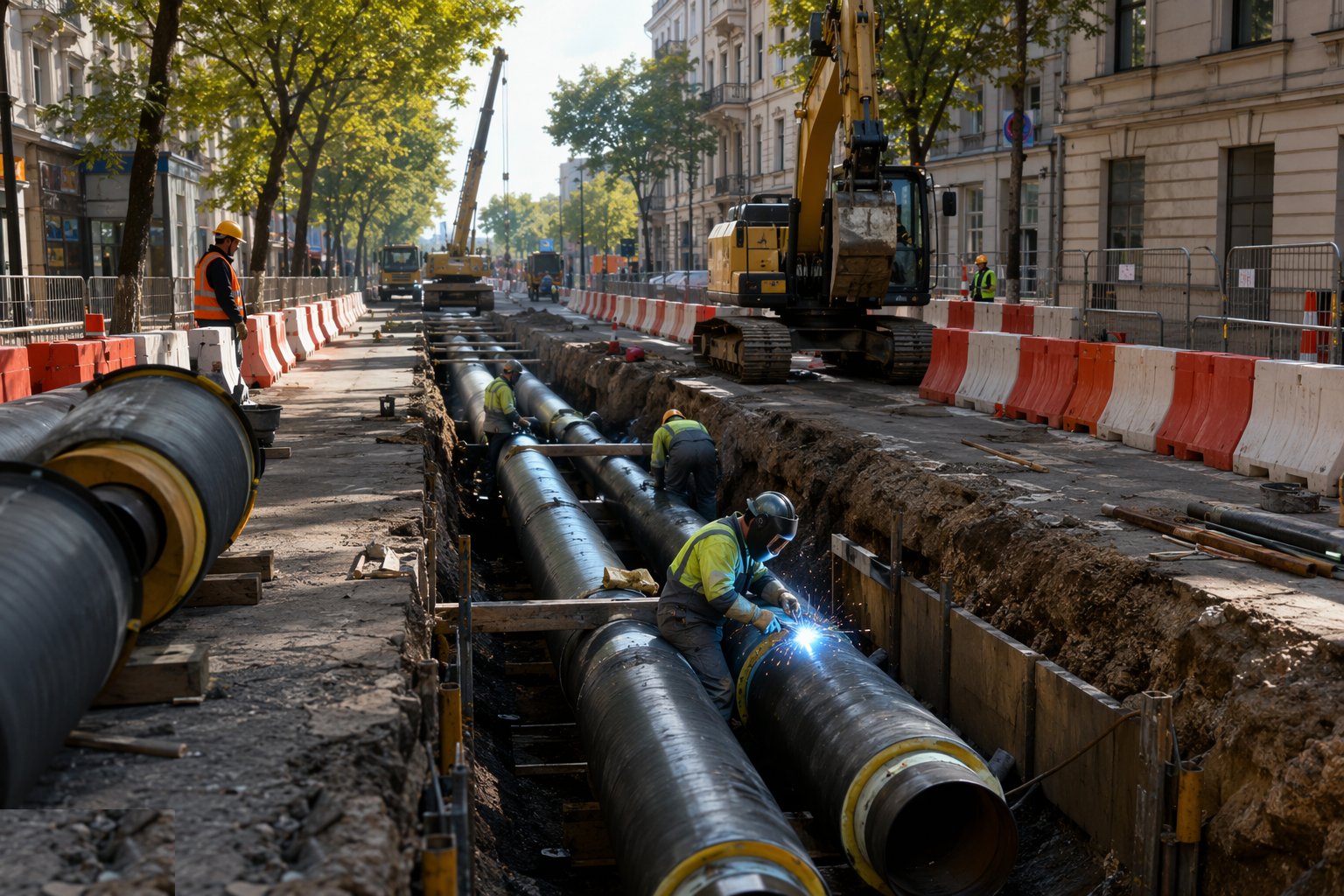
The corridor is proven before a bucket touches it: utility records plotted, trial holes excavated at crossings and congestion points, levels and positions of existing plant recorded, and the pipe alignment adjusted in the design where reality disagrees with the drawing. Street works notices and permits are secured — NRSWA process in the UK, municipality and road authority NOCs in the Gulf — with traffic management designed for a trench that advances daily through a live street. Deliveries are planned so pipe sticks land just ahead of the dig; a heat network's site is two kilometres long and forty metres wide, and logistics is the trade nobody priced.
Step 2: Excavate and prepare the trench
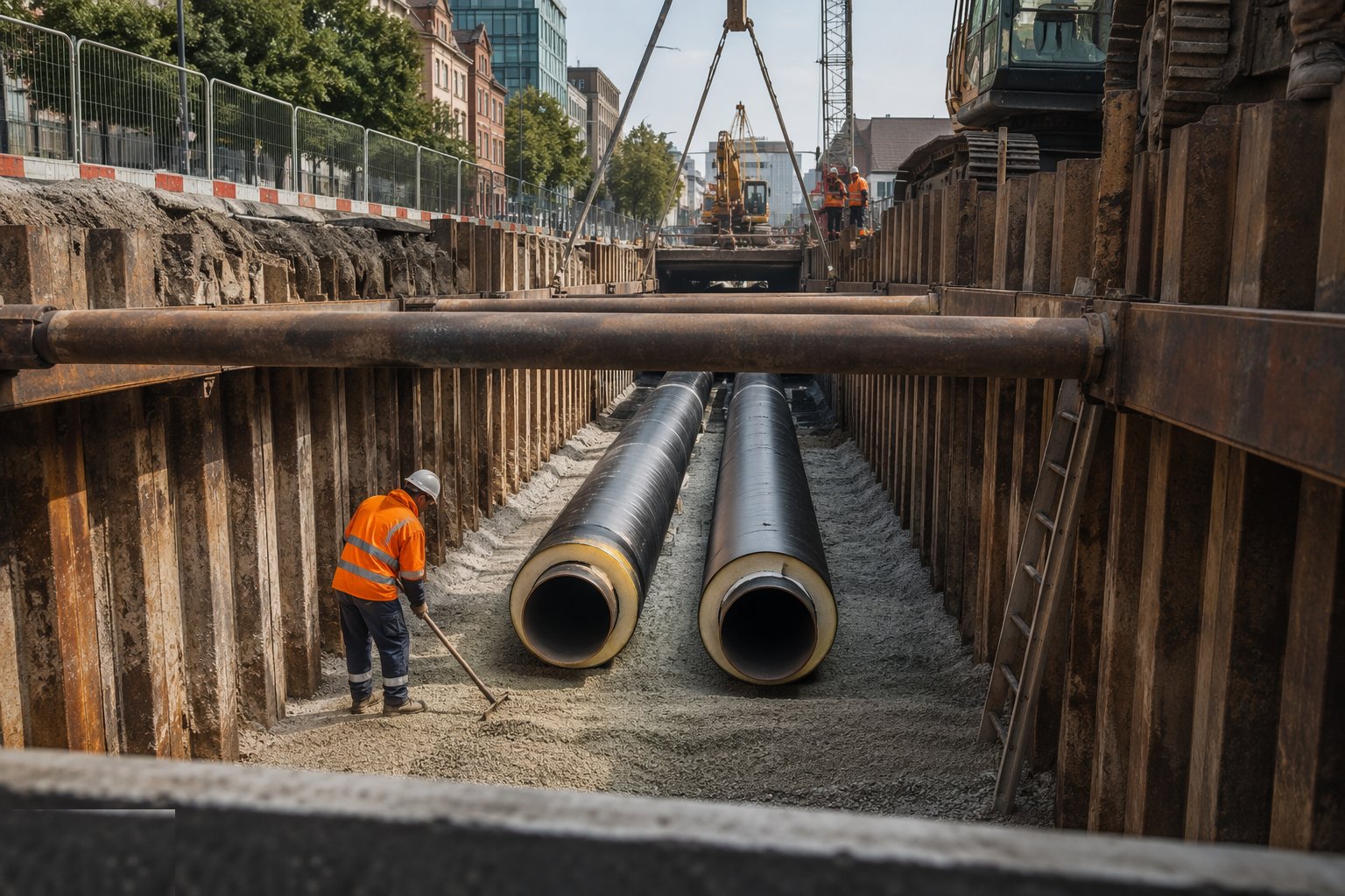
The trench is cut to the design depth and width — enough working room beside the pipe for welders and joint casings, typically a few hundred millimetres each side — with support or battering as the ground and depth demand, and groundwater dealt with by pumping or wellpoints where it appears. The formation is trimmed and the sand bed laid and compacted to level, because the pipe sits on that bed for fifty years. Crossing services are exposed by hand, slung or protected per the undertaker's requirements. In coastal Gulf corridors the water table arrives early and salty: dewatering, trench stability and the corrosion story for any exposed steelwork all sharpen up together.
Step 3: Lay, align and weld the pipe strings
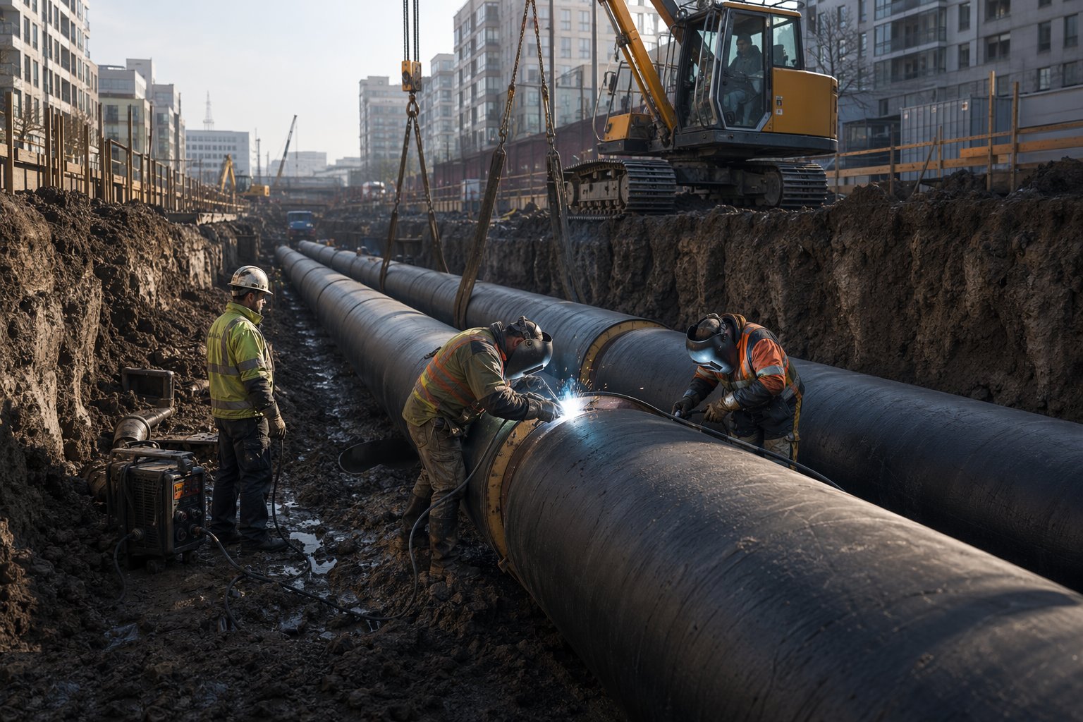
Pipe sticks are lowered and aligned on the bed — line and level matter because the foam casing cannot be bent into compliance afterwards — and the joints welded: butt welds by qualified welders to approved procedures, with the weld prep, root run and cap done as the procedure says, not as the afternoon allows. Weld testing follows the specification: visual on every joint, radiographic or ultrasonic examination on the specified percentage, and full traceability from weld number to welder to test result. Anchors and expansion features are installed exactly where the thermal design puts them — this is the step where the drawing is gospel, because buried expansion systems cannot be inspected once the sand goes back.
Step 4: Insulate the field joints and connect the alarm wires
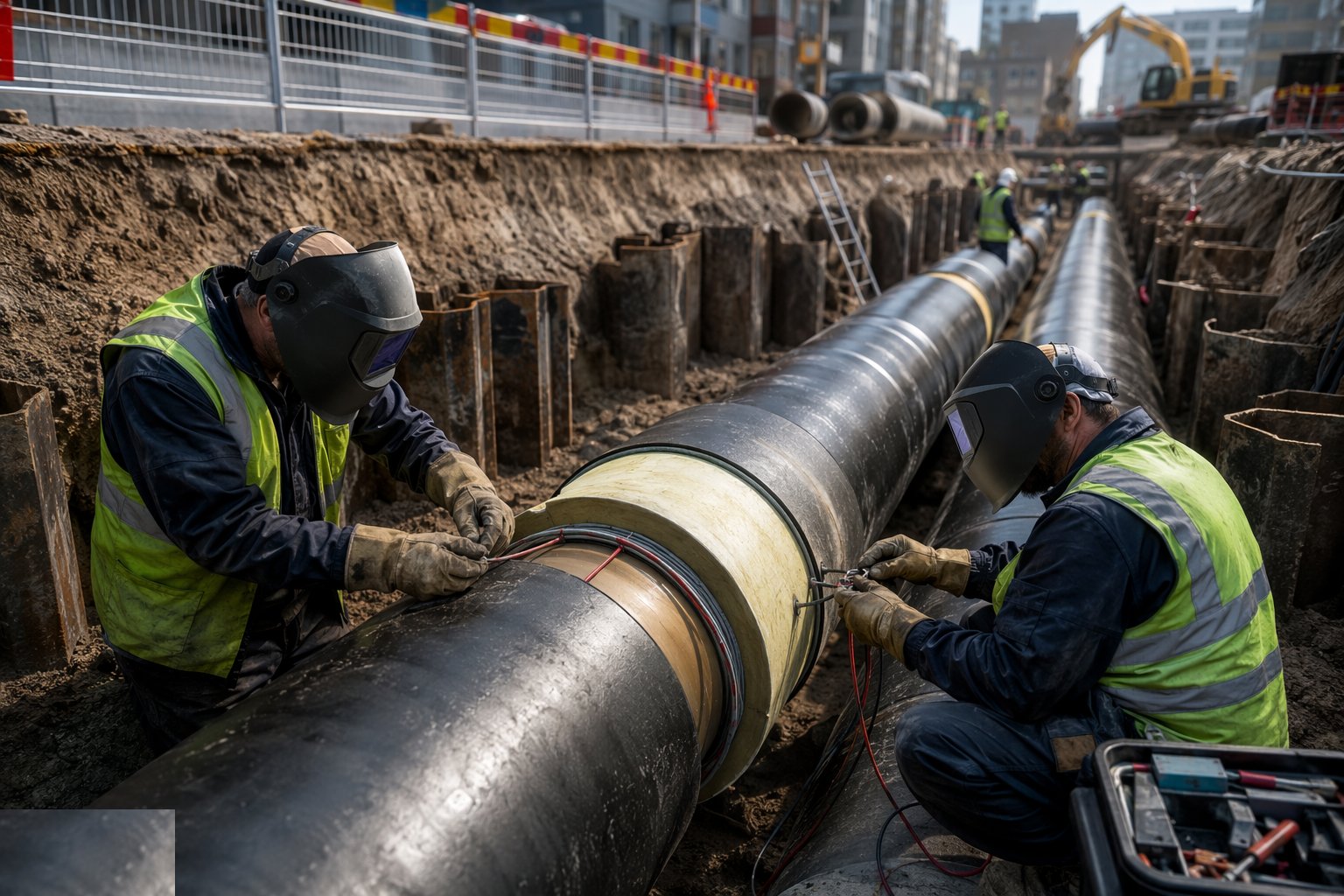
Every welded joint gets its site insulation: the joint casing fitted over the exposed steel, sealed, and injected with polyurethane foam through its ports until the cavity is full — verified by vent holes and the foam supplier's procedure, with the joint surfaces clean and dry because water sealed inside a joint is corrosion with a head start. The alarm wires are connected across every joint, crimped and tested for continuity loop by loop, so the finished network reports moisture location to the monitoring system. This is the most skimped step on a bad job and the most witnessed step on a good one: the joint is the only non-factory insulation in the system, and the network's fifty-year promise lives in it.
Step 5: Backfill, compact and reinstate
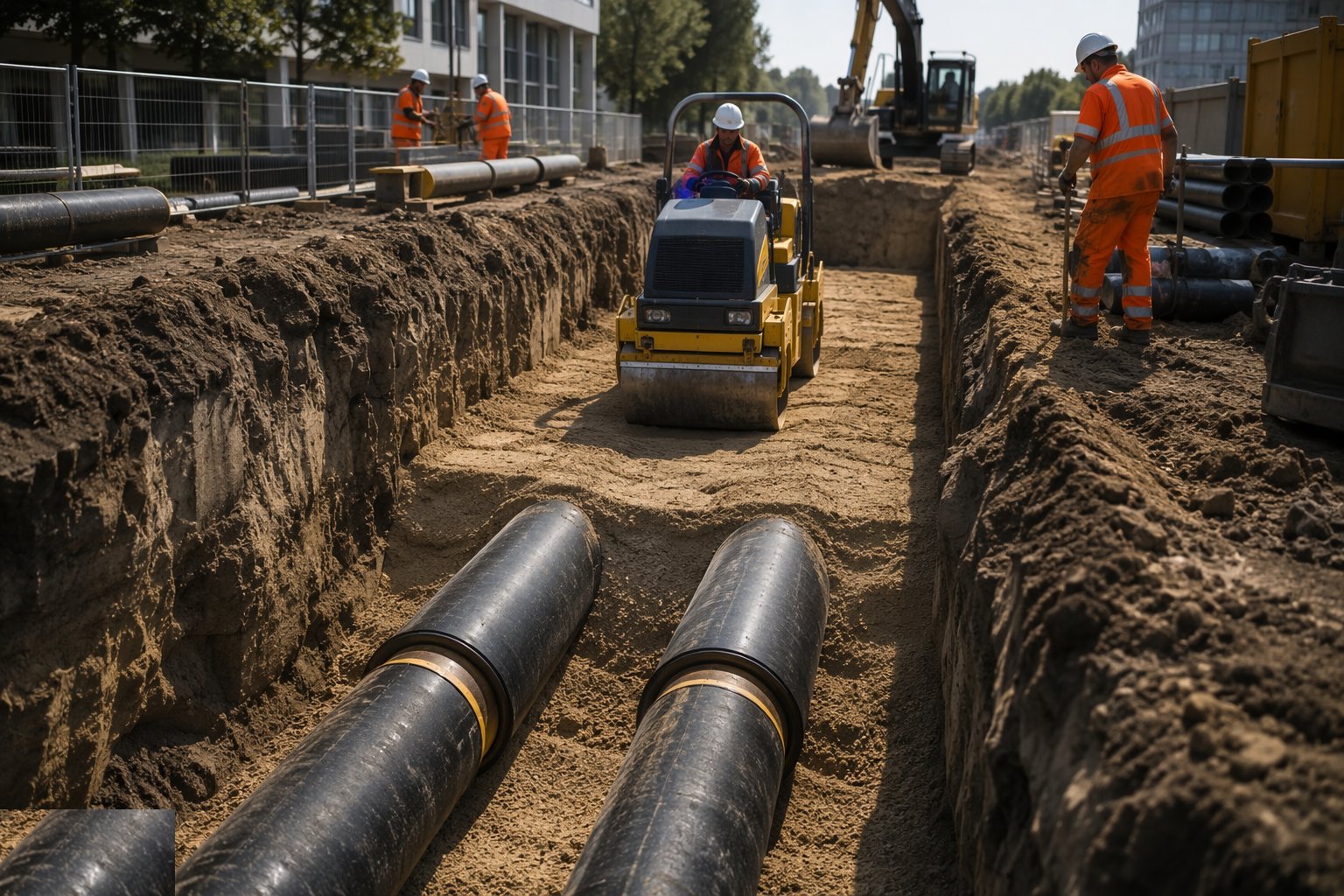
The surround goes back in compacted sand layers to the specified depth above the casing — the compaction is what generates the soil friction the restraint design assumes, so it is tested, not assumed — with warning tape above and selected backfill or foamed concrete per the spec to formation. Chambers are built around valves, vents and drains with their ironwork set to finished level, and building entries are sealed and sleeved. Reinstatement to the SROH structure (or the Gulf municipality equivalent) closes the trench, with the guarantee period running. As-built survey records the main's position, depth and every chamber, because the next twenty years of street works will be planned off this drawing.
Step 6: Flush, pressure-test and commission the alarm system
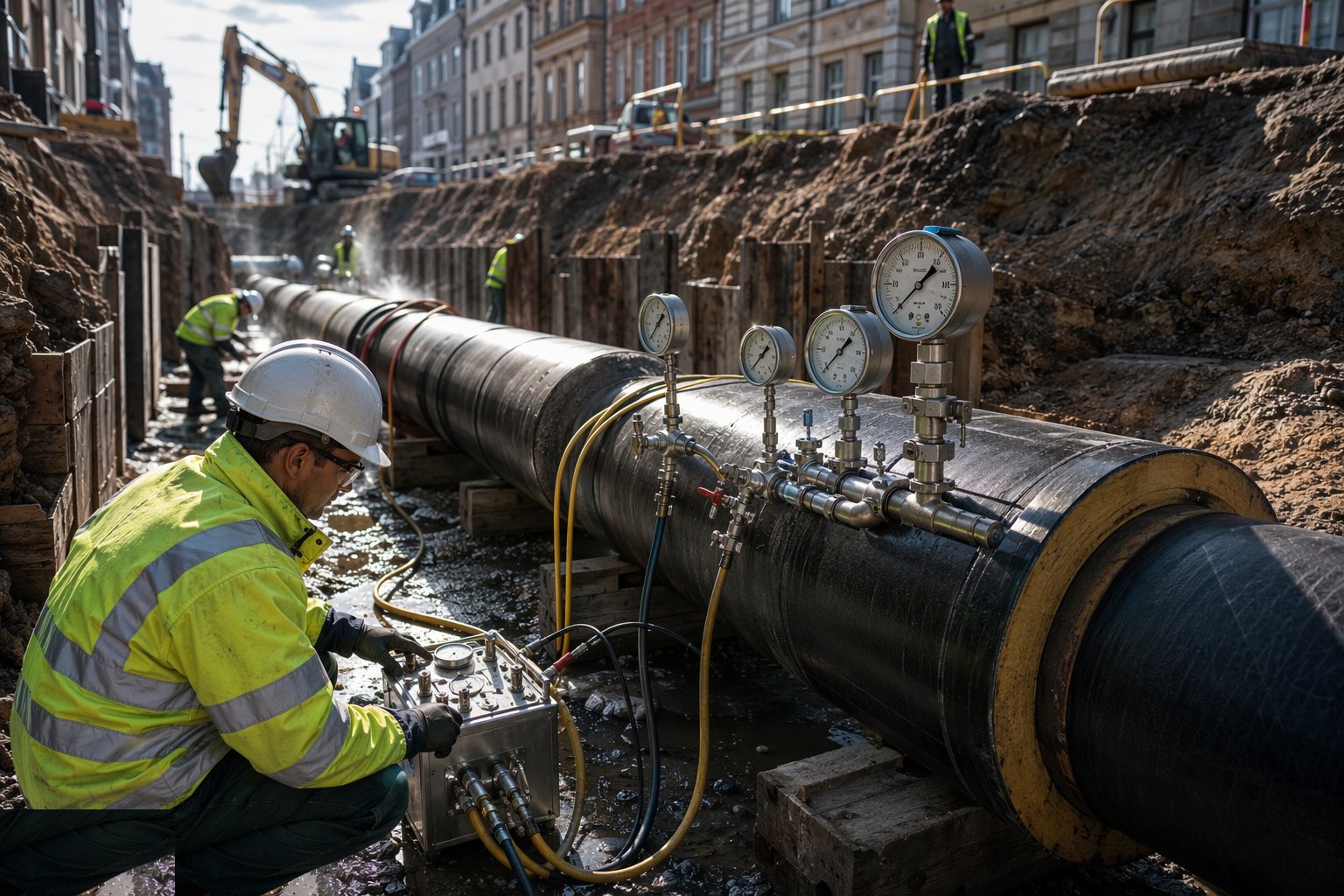
The completed section is flushed to remove the construction debris that would otherwise tour the network's valves and heat exchangers, then pressure-tested to the specification — typically 1.5 times design pressure on the carrier, held and logged — and the alarm wire system is commissioned end to end: continuity, insulation resistance and the monitoring panel mapped to the as-built chainages. Air is vented, the section is chemically conditioned where the water treatment spec says so, and the main is handed over ready for connection to the energy centre and customers. A section that fails its test at this stage is a nuisance; one that fails in service is a bus route dug up in January.
Plant and equipment
- Excavators, trench support (boxes, sheets) and dewatering sets
- Pipe-handling equipment: side booms or excavators with certified lifting gear for heavy cased pipe
- Welding sets, bevelling and alignment clamps; radiographic/UT testing subcontractor equipment
- Foam injection kits and joint casings; alarm-wire crimping and continuity test sets
- Wacker plates and rollers for surround compaction; in-situ density test kit
- Thrust-boring or directional drilling rigs for no-dig crossings
- Flushing pumps, hoses and temporary tanks; pressure test rigs with calibrated gauges and chart recorders
- Chapter 8 traffic management and vacuum excavator for trial holes
Quality control checks
- Weld procedure and welder qualification records; NDT results traceable to joint numbers
- Joint casing and foam injection records per joint, with alarm-wire continuity proven after each connection
- Bedding and surround compaction test results filed against chainage
- Pressure test certificates (carrier and, where specified, casing) witnessed and logged
- Flushing and water-treatment records; alarm system commissioning mapped to as-built chainages
- As-built survey of the main, chambers and service crossings issued to the network operator
Safety considerations
- Deep trench work in live streets: support, access, edge protection and barriers maintained around the clock
- Buried and crossing services: trial holes, permits-to-dig and hand excavation near live gas, HV and comms
- Hot work welding in trenches: fire watch, gas testing where near gas mains, and fume control in confined digs
- Lifting operations for heavy cased pipe over open excavations: planned lifts, certified gear, exclusion zones
- Pressure testing: exclusion zones, controlled pressurisation and calibrated relief — a failed joint under test is shrapnel
- Heat stress management for Gulf summer trench gangs, with midday-break rules observed
Common defects
- Field joints foamed over wet or dirty steel, corroding in service until the alarm wire earns its keep
- Expansion loops or anchors displaced or omitted in construction, so the pipe finds a weld to fail instead
- Surround poorly compacted, removing the soil restraint the thermal design assumed and overstressing bends
- Alarm wires broken or misconnected at joints, leaving the network blind exactly where leaks start
- Debris left in the main and flushed into customer heat exchangers on first fill
- Chambers set low or ironwork poorly bedded, ponding water over the valves the operator needs to reach
Best suited for
- New district heating networks from energy centres through development or city streets
- Gulf district cooling distribution in chilled-water primary and secondary mains
- Network extensions and infill connections to existing heat or cooling schemes
- Low-temperature fourth-generation networks using flexible polymer pipe
How long does District Heating & Cooling Networks take?
Typical duration: A street crew lays and joints 20–60 m of main per day depending on diameter and congestion; a 2 km twin-main corridor typically runs 6–12 months including chambers, testing and reinstatement, with permits and crossings setting the pace..