Energy Centre Construction
The plant room that heats or cools a district — boilers or chillers the size of buses, thermal stores, flues, pumps and a BMS to conduct them — installed, connected and brought online one customer at a time.
Last updated 2026-07-28 by the BuildPedia Editorial Team.
What is Energy Centre Construction?
The energy centre is where the network's product is made. A district heating energy centre is built around its heat sources: gas-fired boilers in modular rows, a CHP engine or two where the spark spread justifies it, increasingly large heat pumps, and thermal stores — insulated buffer vessels holding megawatt-hours of hot water to shave the peaks. A Gulf district cooling plant substitutes electric centrifugal chillers in long halls, with chilled-water thermal storage tanks that let the plant make ice-cold water at night and sell it through the afternoon peak. Around the primary plant sits everything that makes it a system: primary pumps and pressurisation units, plate heat exchangers hydraulically separating the network from the building, water treatment, controls and the BMS that runs the merit order of which machine fires when.
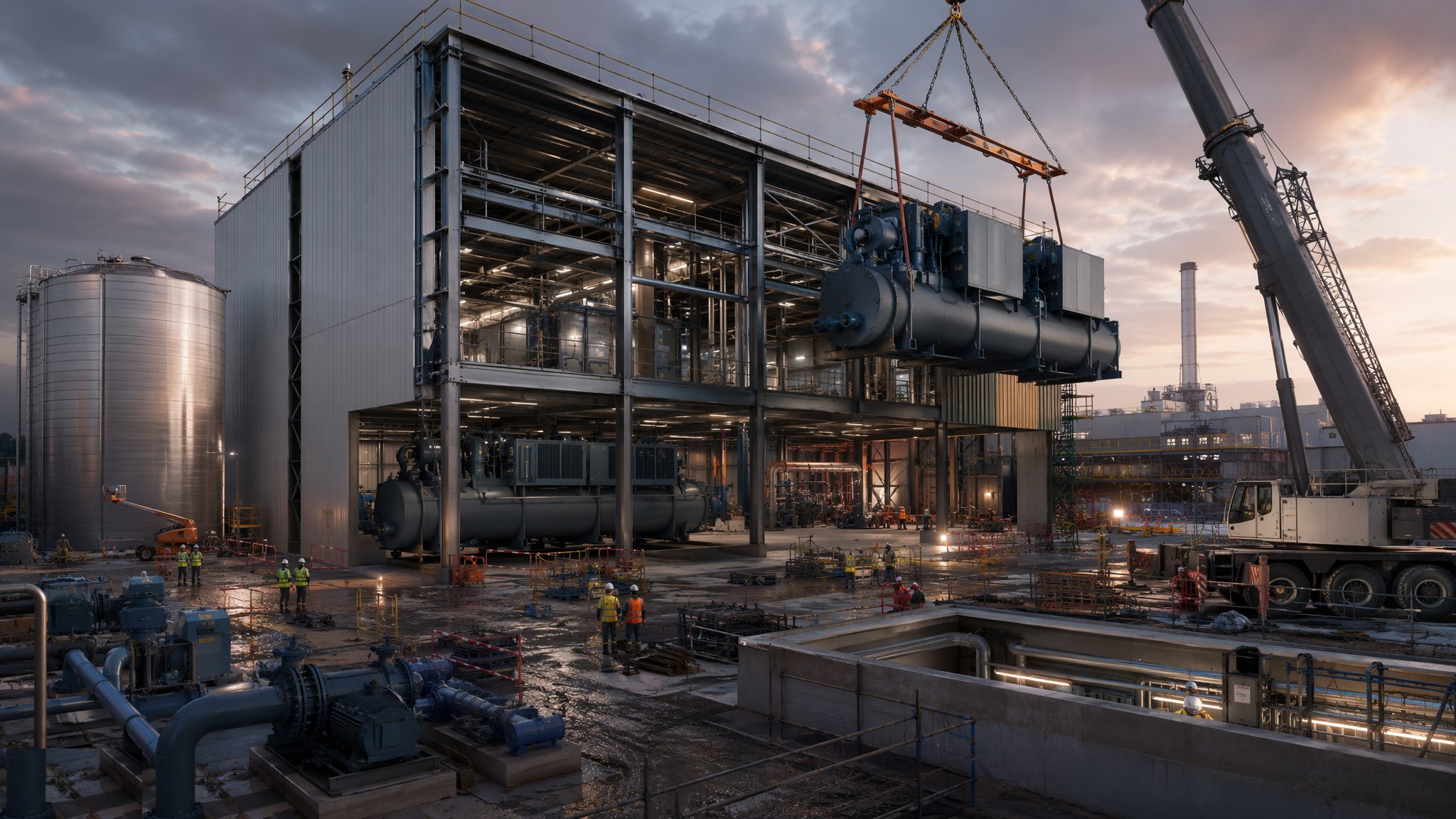
Construction-wise, an energy centre is a heavy MEP job inside a building that is often being finished around it. The plant arrives big — chillers and boilers set the structural brief, not the other way round — so the building is sequenced to let the heavy lifts in: bases cast with holding-down bolts and plinths to the manufacturer's tolerances, a lift route (removable roof section, oversized doors, or a crane through a wall left out) planned before the frame closes. Flues and stacks take boiler exhaust up and out, sized and supported as structures in their own right, and acoustic treatment — attenuators, lined plant rooms, anti-vibration mounts under every rotating machine — is designed in because an energy centre is usually somebody's neighbour.
The distinguishing discipline is phasing. Networks rarely connect all their customers on day one; the energy centre is built with the pipework, electrical capacity and control architecture for the full scheme but commissioned in stages as loads come online. That means the first phase must run efficiently at a fraction of design load (the reason for modular boilers and multiple chillers rather than one giant machine), the BMS must accept new hydraulic interface units being added live, and every subsequent connection is a planned tie-in to a running plant. In the UAE the cooling plants of Empower, Emicool and Tabreed run under municipality and Civil Defence approvals with DEWA supplies sized like small substations; in the UK the gas and emissions consents, the building warrant and the network's own technical standards govern.
When and why is Energy Centre Construction used?
The energy centre is built once the network's first-phase loads are committed — it is the most capital-dense structure in the scheme and the one whose lead times (chillers and boilers can run six months plus) sit on the critical path from the start. Its configuration follows the load profile: modularity where loads ramp up over years, thermal storage where peaks are sharp and tariffs or carbon favour load-shifting, CHP where there is a baseload heat demand to justify the engine. Construction phasing is chosen so early customers get heat or cooling while later phases are still being built — which makes commissioning strategy a design decision, not an afterthought. Get the interfaces wrong — bases out of tolerance, lift route forgotten, BMS architecture that cannot grow — and the plant that should anchor the network's economics becomes its bottleneck.
Types of Energy Centre Construction
Gas boiler district heating centres
Rows of modular high-efficiency boilers with primary pumping, pressurisation and plate heat exchangers to the network. The conventional UK answer: well understood, fast to consent, and modular enough to run efficiently from first customer to full build-out.
Chilled-water district cooling plants
Electric centrifugal chillers (often in pairs duty/standby) with cooling towers or sea-water rejection, chilled-water thermal storage tanks and primary distribution pumping. The Gulf standard, where cooling is the dominant energy use and centralisation wins on efficiency and peak demand.
CHP-led and multi-source centres
Gas engines or turbines generating power with heat recovery into the network, alongside boilers for peak and backup. Higher capital and more consent burden, justified where baseload heat demand and electricity prices make the engine earn its keep across the year.
Heat pump energy centres
Large air-, water- or ground-source heat pumps feeding low-temperature networks, often with thermal stores to run on cheap-rate or low-carbon electricity. The growth market for new UK schemes; they demand low network temperatures and bigger flows, which the whole network design must respect.
Energy Centre Construction: step by step
Step 1: Cast the bases and prepare the lift route
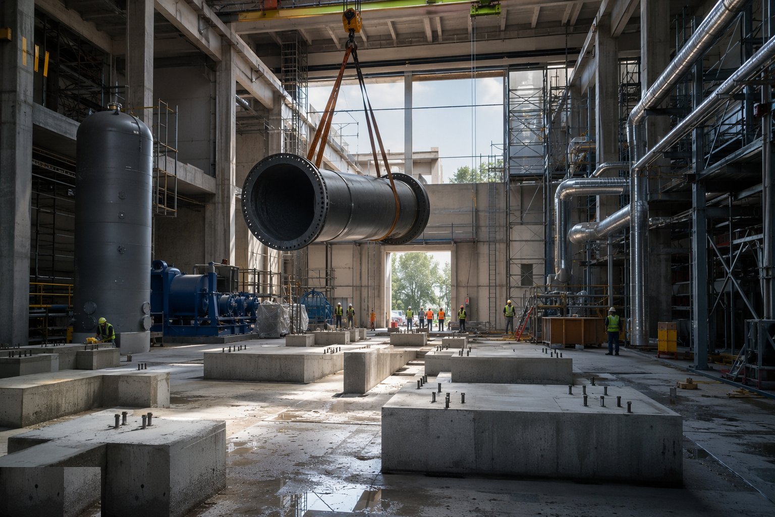
The civils lead: machine bases and plinths cast to the plant supplier's drawings with holding-down bolts set on templates, tolerances of a few millimetres on position and level because a chiller does not shim gracefully. Pipe trenches, ducts and drainage in the plant room floor go in before the slab is power-floated, and the thermal store and tank bases get their load-spreading design — a full chilled-water store is hundreds of tonnes on the ground-bearing slab. The lift route is engineered before the building closes over it: crane positions, ground bearing for the outriggers, roof panels or wall sections left out, and the sequence agreed so the biggest machine lands before the building makes it impossible.
Step 2: Heavy lift and set the primary plant
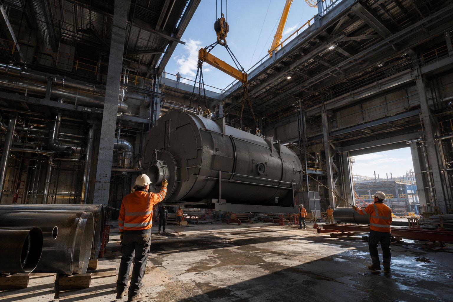
Boilers, chillers and thermal stores arrive on low-loaders and go in on the crane or, inside the building, on skates and gantries to their final positions. Each machine is levelled on its mounts, holding-down bolts grouted with non-shrink grout and torqued after cure, and anti-vibration mounts set to the supplier's deflection spec — a chiller bolted down crooked vibrates itself and its pipework loose over the coming years. Alignment of pump sets and any engine-driven plant is laser-checked to the coupling tolerances. Every machine's position is recorded against the design before pipework starts, because prefabricated pipe spools made to the drawing do not forgive a chiller that wandered 50 mm.
Step 3: Install pipework, flues and stacks
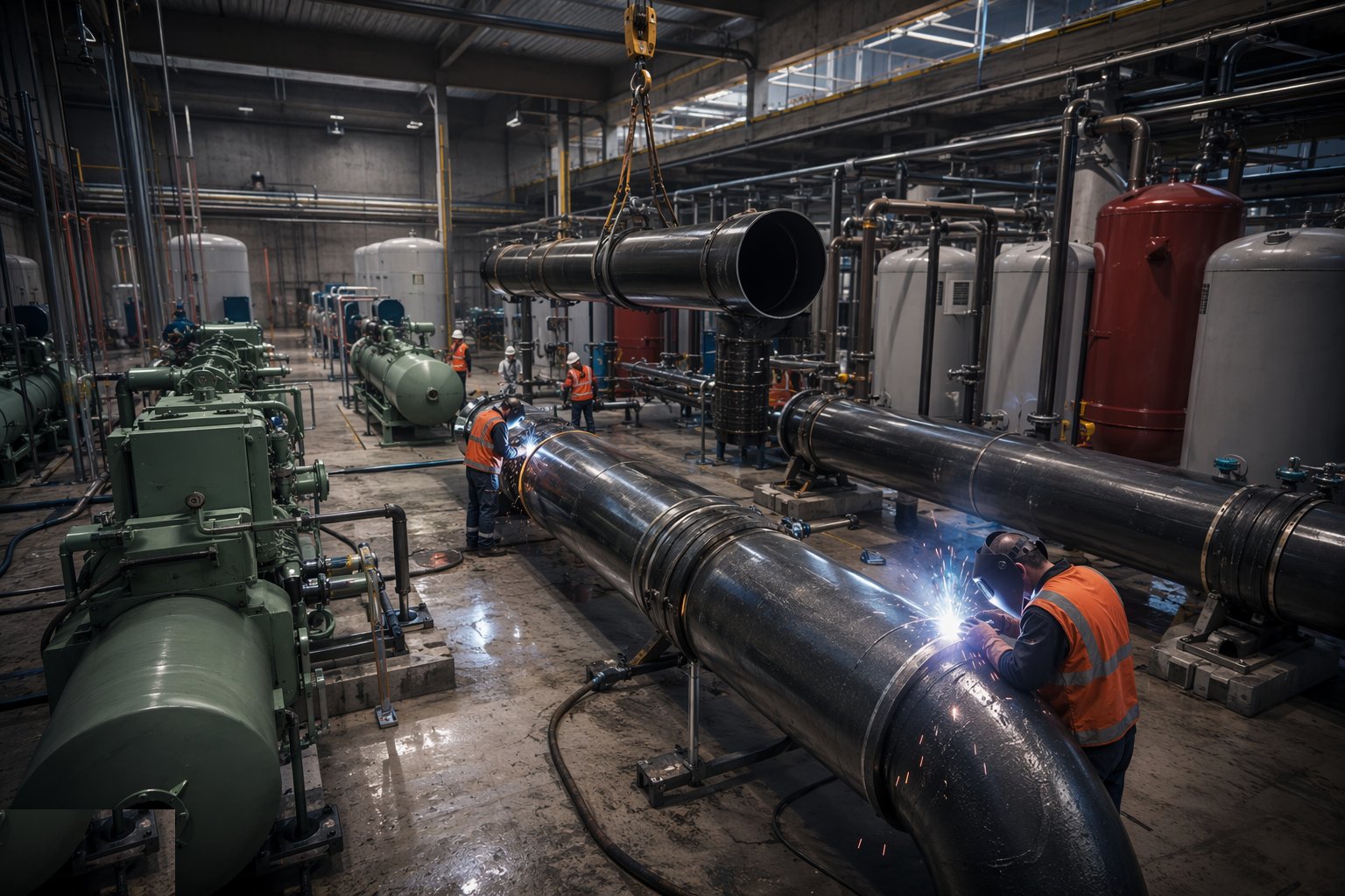
The primary pipework — large-bore welded steel, often prefabricated in spools off-site — is erected on its supports with expansion taken by the designed loops and bellows, anchors and guides placed where the stress analysis says. Welds are tested per the spec (visual plus the specified NDT percentage), flanges torqued in sequence, and the whole system supported so no machine nozzle carries pipe weight — nozzle loading limits are in the data sheet and they are not negotiable. Flues and stacks go up as engineered structures: sectional or welded risers with their support steelwork, linings, and terminations at the consented height, draught-tested before the boilers fire. Insulation and cladding follow the pressure test, not before it.
Step 4: Wire the power and build the controls
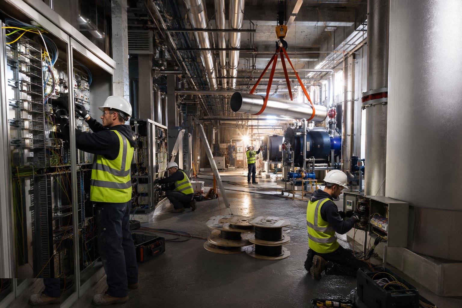
The electrical installation runs from the intake — a serious supply, with district cooling plants drawing megawatts through their own transformers — to MCCs, starters and VSDs on the pumps and fans, with the cabling and containment sized for the motor loads and their harmonics. Instruments are fitted as pipework completes: flow meters, temperature pockets, pressure tappings, all accessible for calibration. The BMS is built panel by panel and the point-to-point testing starts — every sensor and actuator proven back to the head end before any sequence is trusted. The control philosophy (merit order, storage charge/discharge, lead-lag rotation) is witnessed against the written spec, because a BMS that sequences badly costs the operator money every hour of the plant's life.
Step 5: Flush, treat and pressure-test the systems
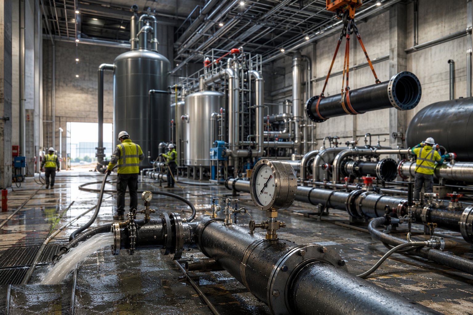
Before any machine runs, the water systems are cleaned: forward flushing at velocities that actually move debris, chemical cleaning where the spec demands, then fill, dose and vent until samples pass. Pressure tests are completed and certified on the closed systems, safety valves fitted and set with their certificates filed, and the water treatment regime — inhibitor, biocide where relevant, monitoring points — established as an operating discipline, not a commissioning day gesture. An energy centre that starts life with dirty water spends its early years weeping through pump seals and fouled plate heat exchangers, and the network connected to it inherits the same gift.
Step 6: Commission plant and connect customers in phases
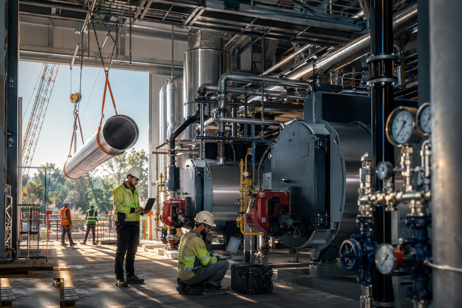
Commissioning runs machine by machine: boilers or chillers fired and proven through their load ranges, safety interlocks and trips tested and recorded, pumps and pressurisation balanced, and the thermal store cycled to prove the charge/discharge logic. Then the phased connections begin: each customer's hydraulic interface (substation or energy transfer station) tied in, flushed, balanced and witnessed, with the network temperatures and flows held stable as load is added — this is where the modular plant strategy pays, because a plant sized for year ten must not short-cycle itself to death serving year one. Performance testing against the guaranteed efficiencies closes the technical file, and the seasonal commissioning plan is agreed, because the plant has not truly been proven until it has seen both extremes of its working year.
Plant and equipment
- Mobile and crawler cranes for the heavy lifts; skates, jacks and gantries for internal positioning
- Welding sets and prefabrication shop facilities for large-bore spoolwork; NDT subcontractor
- Laser alignment kit for rotating plant; torque and tensioning equipment
- Flushing rigs, temporary tanks and chemical-cleaning equipment; water test kits
- Calibrated pressure test rigs, safety-valve test equipment
- BMS panels, point-to-point test equipment and laptop-based commissioning tools
- Load banks and temporary supplies for pre-connection proving
- MEWPs and access towers for high-level flue and pipework installation
Quality control checks
- Base and plinth surveys against supplier tolerances before machines are set; grout and torque records after
- Weld traceability and NDT records for primary pipework; flange torque logs
- Pressure test and safety-valve certificates filed per system
- Flushing, chemical cleaning and water-sample results signed off before plant runs
- Point-to-point BMS testing records and witnessed sequence-of-operations tests
- Performance test results against guaranteed duties, with seasonal commissioning plan agreed
Safety considerations
- Heavy lifts into partially complete buildings: planned lifts, appointed persons, exclusion zones and weather limits
- Confined spaces in tanks, thermal stores and large vessels: entry procedures, gas testing and rescue plans
- Stored energy on commissioning: pressurised systems, live electrical switchgear and rotating plant under permit
- Chemical handling for cleaning and dosing: COSHH assessment, PPE, spill kits and eyewash
- Hot surfaces and live firing during boiler/chiller proving: boundaries, communication and competent supervision
- Noise and vibration exposure for commissioning teams spending weeks inside a running plant room
Common defects
- Machine bases out of tolerance or grout voids under baseplates, leading to vibration and alignment drift in service
- Pipework forced onto machine nozzles, cracking connections or pulling couplings out of alignment within the first year
- Systems filled without proper flushing, so debris fouls plate heat exchangers and control valves from day one
- BMS points mislabelled or sequences never witnessed, leaving the plant hand-cranked by operators forever
- Acoustic treatment value-engineered out, generating noise complaints from neighbours the planning consent promised to protect
- Safety valves fitted without certificates or set wrong — the last line of defence treated as a spare part
Best suited for
- District heating schemes where central plant serves buildings through a buried network
- Gulf district cooling plants with chillers and thermal storage serving dense developments
- Phased masterplans where plant must run efficiently from first customer to full build-out
- Decarbonisation retrofits replacing building boilers with a networked central source
How long does Energy Centre Construction take?
Typical duration: A mid-sized energy centre runs 9–18 months from civils to first export, with chiller/boiler lead times and the phased connection programme setting the tail; full build-out commissioning follows the customer connection schedule, often across several years..