Ground Improvement Techniques
Making weak ground carry the building it could not: stone columns, dynamic compaction, rigid inclusions and soil mixing — chosen on soil and load, built on a proper working platform, and proven by testing.
Last updated 2026-07-28 by the BuildPedia Editorial Team.
What is Ground Improvement Techniques?
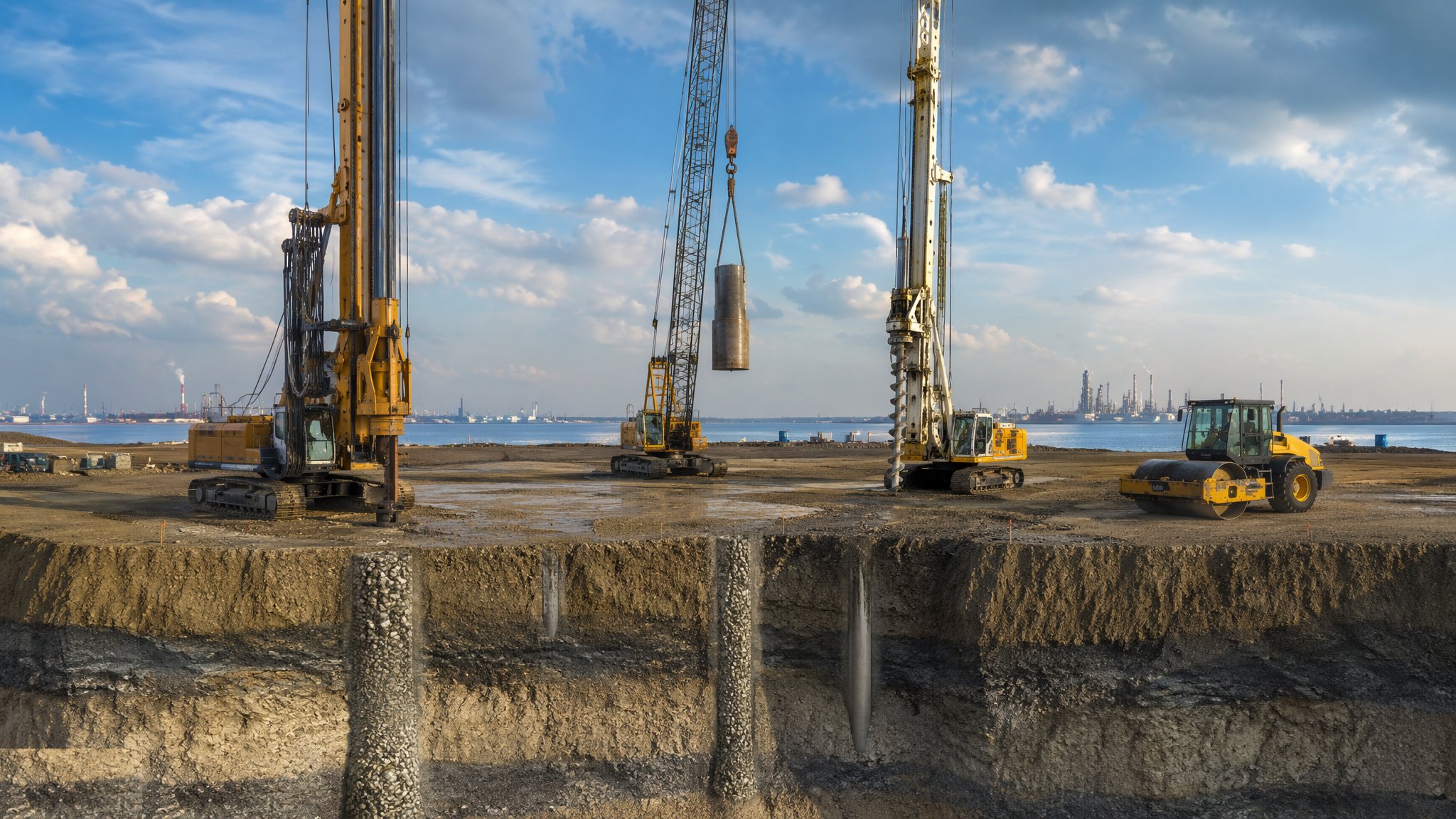
Ground improvement lives in the gap between shallow foundations and piling: ground too weak for strips and rafts at sensible cost, but not bad enough to justify a piled solution — or sites where settlement, not bearing, is the enemy. The methods share one logic: change the ground's behaviour rather than bypass it. Vibro stone columns (vibro replacement) drive a poker vibrator into soft clays or loose fills and backfill the bore with compacted stone, creating stiff columns that reinforce the soil mass and drain it; vibro compaction densifies clean sands without stone at all. Dynamic compaction is the blunt instrument: a pounder of 8–20 tonnes dropped from 10–25 m in a grid, cratering and densifying fills and loose natural soils in passes, with the craters levelled between them — crude, spectacular, and remarkably effective on the right ground.
The engineered end of the menu uses concrete and grout. Rigid inclusions — CMCs (controlled modulus columns) and similar — are small-diameter concrete columns installed with displacement augers, acting with a granular load-transfer platform over their heads to carry slabs and embankments: the ground and the columns share the load, so settlement is controlled without piling to depth. Deep soil mixing blends cement or lime binder into soft clays in place, producing soil-cement columns or panels — widely used under tanks, embankments and infrastructure. Each method has its ground: stone columns want clays that can hold a bore and soils that drain; dynamic compaction wants granular fills well above the water table and sites far from neighbours; soil mixing wants soft cohesive ground; rigid inclusions work where a competent stratum exists to take the column toes.
Two disciplines govern every technique. First, the working platform: the rigs are heavy, tall and top-loaded, and the platform they stand on must be designed — thickness, material, geosynthetic reinforcement — maintained through the works, and certified under the FPS Working Platform Certificate regime, exactly as for piling. Rig overturns on soft spots kill. Second, verification: ground improvement is one of the few trades where you build the ground and then test it — pre- and post-treatment CPTs to show the densification, plate load tests on individual columns, zone tests loading groups of columns under a kentledge stack to prove the composite behaviour. The design assumptions are written down, the test regime is agreed before mobilisation, and the treated ground is signed off against acceptance criteria — because the building that follows has no other foundation than the ground you just made.
When and why is Ground Improvement Techniques used?
Ground improvement applies to warehouse and industrial slabs on soft or made ground, housing on variable fill, embankments and infrastructure on soft alluvium, tanks and hardstandings with tight settlement criteria — anywhere piling is overkill but untreated ground will not perform. It sits after earthworks to formation and before foundations and slabs, and its method selection is made early, on the ground investigation: the wrong technique for the soil is money spent moving mud. It matters commercially because it routinely halves foundation cost against piling and can make unbuildable plots viable; it matters technically because the failure mode is differential settlement — a slab or structure cracking over months as untreated pockets consolidate — which arrives after handover and stays for the life of the building. The technique also writes constraints into everything downstream: services layouts across treated ground, drainage through stone column fields, and construction trafficking limits on the platform are all set by what was done to the ground.
Types of Ground Improvement Techniques
Vibro stone columns (vibro replacement)
Poker vibrators — top-feed in stable ground, bottom-feed with tremie stone in soft or wet ground — forming compacted stone columns typically 450–900 mm diameter on a grid. Reinforces and drains soft clays and fills under slabs and embankments; executed to BS EN 14731.
Vibro compaction
The same depth vibrators used without stone to densify clean granular soils and hydraulic fills — the sand compacts round the poker under water flush. Cheap and fast where the soil is right, useless in clay; verified by the before-and-after CPT profile.
Dynamic compaction
Repeated pounding of the surface by a dropping weight in a planned grid of passes, craters backfilled between passes. Powerful on made ground and loose granular deposits, constrained by vibration limits near structures and by the water table — and by neighbours, who will hear every blow.
Rigid inclusions / CMCs
Displacement-auger concrete columns, typically 280–450 mm, taken to a competent stratum and capped by a granular load-transfer platform that shares load between columns and soil. Settlement control without piling — the modern default under big slabs and embankments on soft ground.
Deep soil mixing
Rotating mixing tools blending cement or lime slurry (wet method) or dry binder into soft clays to form soil-cement columns, walls or mass stabilised blocks. Carries tanks, roads and embankments on very soft ground; strength verified by coring and testing the treated column.
Ground Improvement Techniques: step by step
Step 1: Select the method and design the treatment

Method selection is a ground investigation exercise, not a sales brochure: particle size and fines content, water table, organic content, existing fill obstructions, and the settlement criteria of the structure above decide the shortlist — vibro for reinforcing and drainage, compaction for clean sands, rigid inclusions where a firm stratum exists, mixing for very soft clays. The design fixes column spacing and depth, the load-transfer platform, the acceptance criteria and the verification testing regime, and a trial area is specified on anything but the smallest schemes — ground improvement designs are calibrated on the actual ground, not on hope.
Step 2: Build and certify the working platform
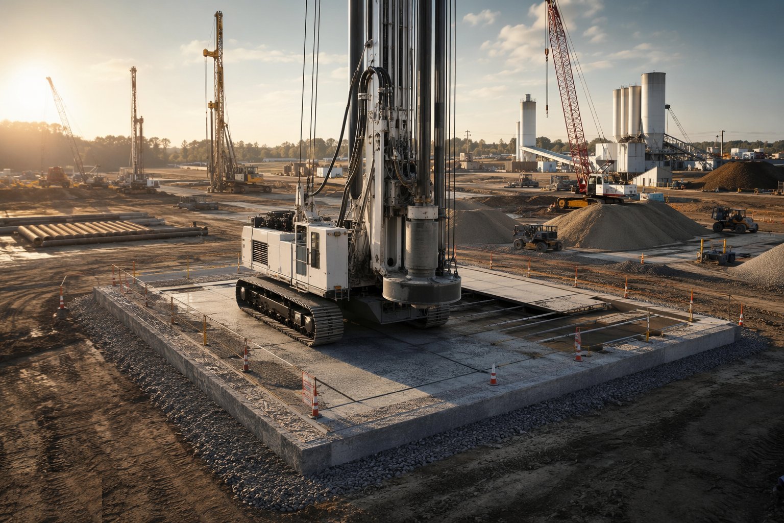
The platform is designed for the rig that will stand on it: granular thickness and geosynthetics from the platform design method, placed and compacted, with edges and ramps engineered — and then maintained, because a platform rutted and ponded by two weeks of rig traffic is no longer the platform that was designed. The FPS Working Platform Certificate is signed and handed over before the rig tracks on; platforms are inspected routinely and re-certified when they are reworked. This is not paperwork for its own sake: the industry's fatal accidents in this trade are rig overturns on inadequate platforms.
Step 3: Run the trial and calibrate
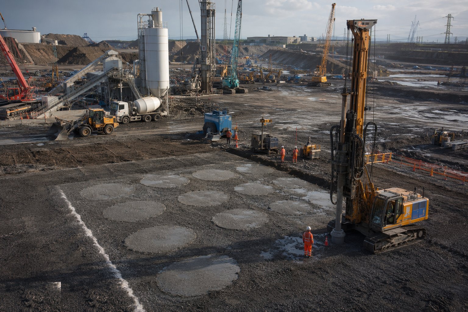
The trial area proves the design before production: columns or pounding at the design spacing, instrumented and tested — CPTs before and after, plate tests on trial columns, settlement monitoring under trial loads. Production parameters are set from the trial: depth refusal criteria, stone consumption per column, binder dosage, pounder energy per pass. A trial that fails is the cheapest education on the project; a trial skipped is how a scheme treats ten thousand square metres of ground wrongly and finds out under the floor slab.
Step 4: Install production treatment
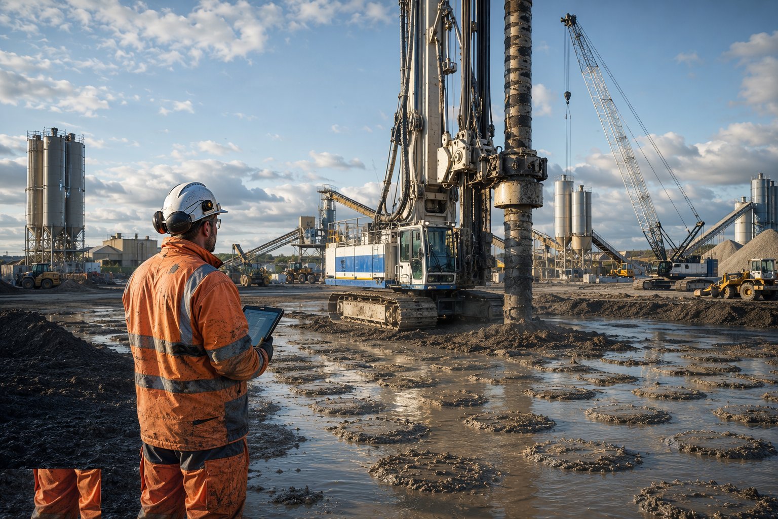
Production runs to the rig's own records: every column logged — depth, time, energy, stone or binder quantity — because the rig data is the first quality record and anomalies in it are where the investigation starts. Sequencing matters: columns installed in an order that does not trap water or heave adjacent fresh columns; dynamic compaction passes with their rest periods for pore pressures to dissipate; soil mixing with its overlap and fresh-to-fresh joint rules. Spoil, slurry and return water are managed as they arise, not shovelled aside for later.
Step 5: Construct the load-transfer platform and surface
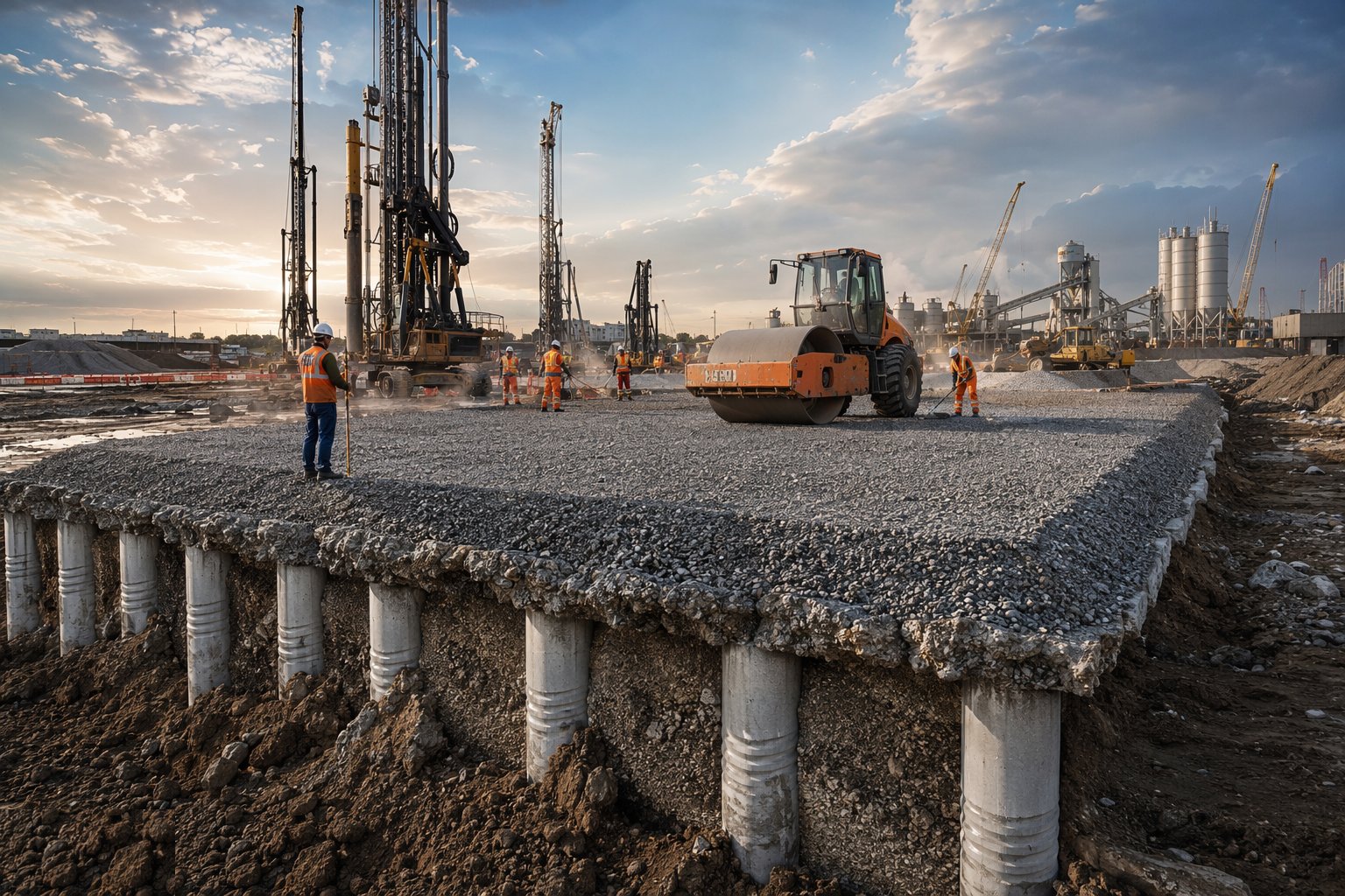
Over rigid inclusions and CMCs, the granular load-transfer platform — designed thickness, graded stone, geosynthetic reinforcement — is placed in controlled layers and compacted, because this mattress is what makes the soil and the columns share load as designed. Formation is then brought to level and tolerance, proof-rolled and protected: treated ground left open to weather and construction traffic is treated ground being un-treated.
Step 6: Verify: testing and acceptance

The verification regime executes the agreed testing: post-treatment CPTs against the pre-treatment baseline, plate load tests on individual columns at the specified rate, zone tests loading representative column groups under kentledge with settlement logged against time and load, coring and strength testing of soil-mixed columns. Results are assessed against the acceptance criteria with the designer; shortfalls are retreated or redesigned before the following trades mobilise. The test file becomes part of the building's foundation documentation — the slab designer, the warranty provider and the insurer all read it.
Plant and equipment
- Vibro rigs: top-feed and bottom-feed depth vibrators with stone delivery systems
- Crawler cranes with pounders and release mechanisms for dynamic compaction
- Displacement auger rigs and concrete pumps for rigid inclusions/CMCs
- Deep soil mixing rigs with binder batching, slurry plant and dosing control
- CPT rigs for pre- and post-treatment profiling
- Plate load test and zone test kentledge, with settlement instrumentation
- Dozers, excavators and rollers for platform and load-transfer platform construction
- Settlement plates, piezometers and data loggers for monitoring
Quality control checks
- FPS Working Platform Certificate signed before rigs mobilise, with routine platform inspections
- Rig instrumentation records per column: depth, energy, stone/binder quantities logged and reviewed
- Pre- and post-treatment CPT profiles compared against acceptance criteria
- Plate load and zone test results with full load-settlement-time records
- Trial area calibration report setting production parameters
- Coring and strength results for soil-mixed columns at the specified frequency
Safety considerations
- Rig stability on working platforms: certificate regime, platform maintenance and exclusion of soft spots
- Dynamic compaction: vibration and flying-debris exclusion zones, pre-condition surveys of neighbours
- Overhead services and buried services clearances before penetration — CAT scans and permits to dig
- Slurry and binder handling: cement burns, pressurised lines and dust control
- Noise and whole-body vibration exposure on rigs and rollers: limits, rotation and monitoring
- Open bores and craters: backfilling, barriers and overnight protection
Common defects
- Wrong method for the ground: stone columns punched into ground too soft to hold them, or compaction attempted in clay
- Platform failure under the rig — rutting, punching and the overturn that follows
- Under-treatment at depth where rigs chased production over refusal criteria
- Settlement after handover from untreated pockets between tested zones — verification grid too coarse
- Load-transfer platform placed thin or un-compacted, decoupling the columns from the slab
- Damage to adjacent structures and services from pounding or vibro energy with no vibration monitoring
Best suited for
- Warehouse and industrial floor slabs on soft or made ground
- Housing and infrastructure embankments on variable fill or alluvium
- Tanks and hardstandings with tight differential settlement criteria
- Sites where piling is technically viable but commercially unjustified
How long does Ground Improvement Techniques take?
Typical duration: Trial and calibration typically run 2–6 weeks; production treatment proceeds at 500–2,000 m² of footprint per rig-week depending on method, with verification testing adding 3–8 weeks including zone test monitoring..