Marine Piling & Jetty Construction
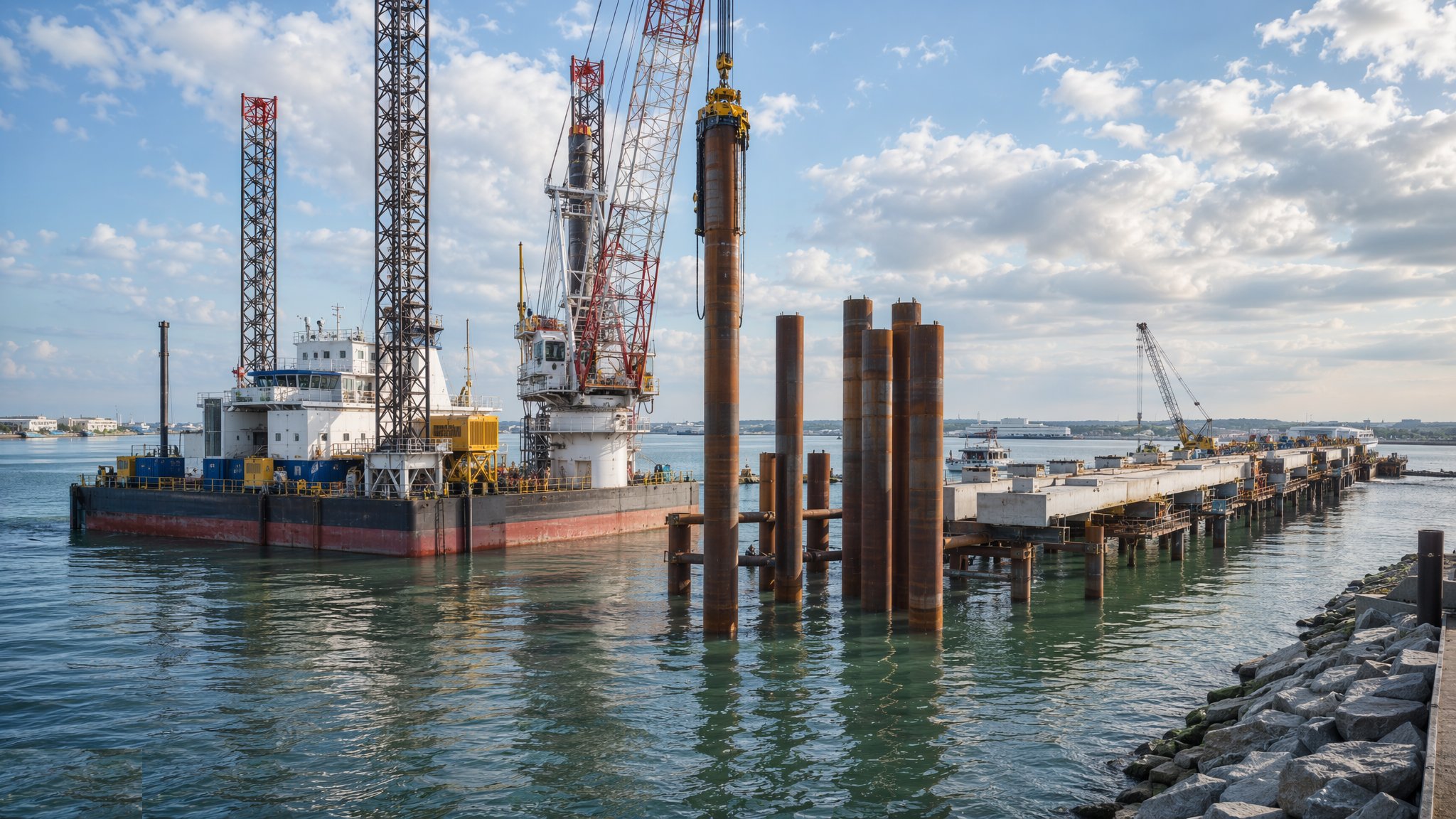
Structures standing in the sea on driven steel — tubular piles pitched and driven from barges and jack-ups, berthing and mooring dolphins, linkspans and access trestles, precast deck units stitched with in situ concrete, cathodic protection fitted, and the whole job danced to the tide tables.
Last updated 2026-07-28 by the BuildPedia Editorial Team.
What is Marine Piling & Jetty Construction?
A jetty is a bridge that expects to be hit. Piled marine structures — jetties, dolphins, linkspans and the trestles that reach them — stand on driven steel because steel piles go through soft seabed to the stratum, take the raking loads of berthing ships and mooring lines, and can be installed from floating plant in water too deep for anything else. The workhorse is the driven tubular steel pile: large-diameter tubes, driven open-ended and cleaned out and concrete-filled where the design calls for it, vertical for the gravity loads and raked — battered, in the older tongue — to take the horizontal shove of a vessel coming alongside. Execution follows the piling standards — BS EN 12699 for displacement piles — with BS 6349 governing the maritime design they serve.
The platform is half the engineering. Piling from a barge means leaders, hammer and crane riding the swell, positioned by RTK and held by anchors, working the weather windows the sea allows; piling from a jack-up means a stable platform legs-down on the seabed, slower to move but steady as land for the precise work. Either way, the sequence is pitch, drive, extend, cut off: piles pitched into the leaders or the template, driven with vibratory hammers where the ground allows and impact hammers to design toe or refusal, welded on in sections when one length is not enough, and cut to level by burning — every cut edge and weld in the splash zone a corrosion detail that must be made good, because seawater keeps its own maintenance schedule.
Above the piles the deck is built in the marine way: precast wherever possible, because concrete cast on land behaves and concrete cast over water must be fought for. Precast beams land on the cropped pile heads, precast deck units span between, and in situ stitches and topping tie it together — or pile caps are cast in situ on hanging formwork where the geometry demands. Dolphins stand alone as the points that take the berthing energy and the mooring lines, connected by walkways; linkspans bridge the tide for ro-ro ramps. And through it all runs the corrosion war: coatings to the splash zone, sacrificial anodes or impressed current cathodic protection below, because a marine structure is never finished — it is only ever defended.
When and why is Marine Piling & Jetty Construction used?
Marine piling runs wherever the port needs structure in open water: tanker and bulk jetties standing off the shore in deep water, ferry berths with linkspans riding the tide, berthing and mooring dolphins holding vessels at a loading terminal, and the trestles carrying pipelines and conveyors to reach them. It matters because these are the most exposed structures in the industry — every weld, cut edge and bolt lives in the most corrosive environment on earth, every pile takes impact loads a building column never dreams of, and every defect is underwater where inspection costs money. The contractor who treats marine piling as land piling with boats learns otherwise at the first winter gale; the one who engineers the tidal working, the corrosion protection and the precast strategy together builds jetties that are still earning when the paperwork is forgotten.
Types of Marine Piling & Jetty Construction
Driven tubular steel piles
Large-diameter steel tubes driven open-ended, cleaned out and concrete-filled with reinforcement where required. The backbone of jetty construction: high capacity, raking capability and installation from floating plant in any water depth.
Piled jetties with precast decks
Rows of piles capped with precast beams and deck units stitched with in situ concrete. Factory quality over open water: the deck goes down fast, the scaffolding is a barge, and the sea gets almost no say in the concrete quality.
Berthing and mooring dolphins
Standalone piled structures taking fender and mooring loads at the vessel's contact points, linked by walkways. Concentrated engineering: a handful of raked piles doing the work of a wall, with every load path designed for the ship that arrives sideways.
Linkspans and ro-ro bridges
Articulated steel bridges spanning from abutment to pontoon or fixed support, riding the tide for vehicle ferries. Piling, precision steelwork and mechanical systems in one structure — the marine job with a machinery handover at the end.
Access trestles and conveyor galleries
Long piled trestles carrying roadways, pipelines or conveyors from shore to jetty head. Repetitive marine piling at production rates — a mile of structure built a bent at a time.
Marine Piling & Jetty Construction: step by step
Step 1: Set up the piling platform and position control
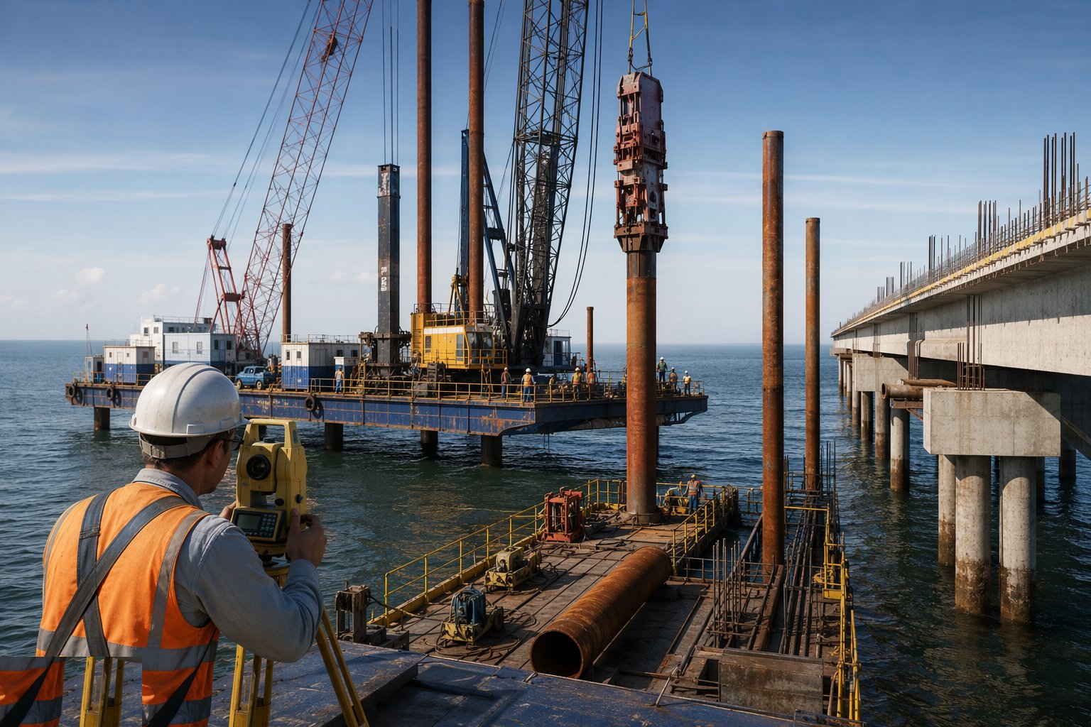
The campaign starts with the platform: the piling barge moored on its anchor pattern with leaders and hammer rigged, or the jack-up jacked down on the seabed with its legs proven. Positioning runs on RTK GNSS with shore control checked in, pile positions translated into the barge's working frame, and the tide and weather limits for each operation written into the daily plan. The seabed at every pile position is confirmed against the ground model — an obstruction found by the pile toe is a day lost, and found by the survey it is a footnote.
Step 2: Pitch and drive the piles
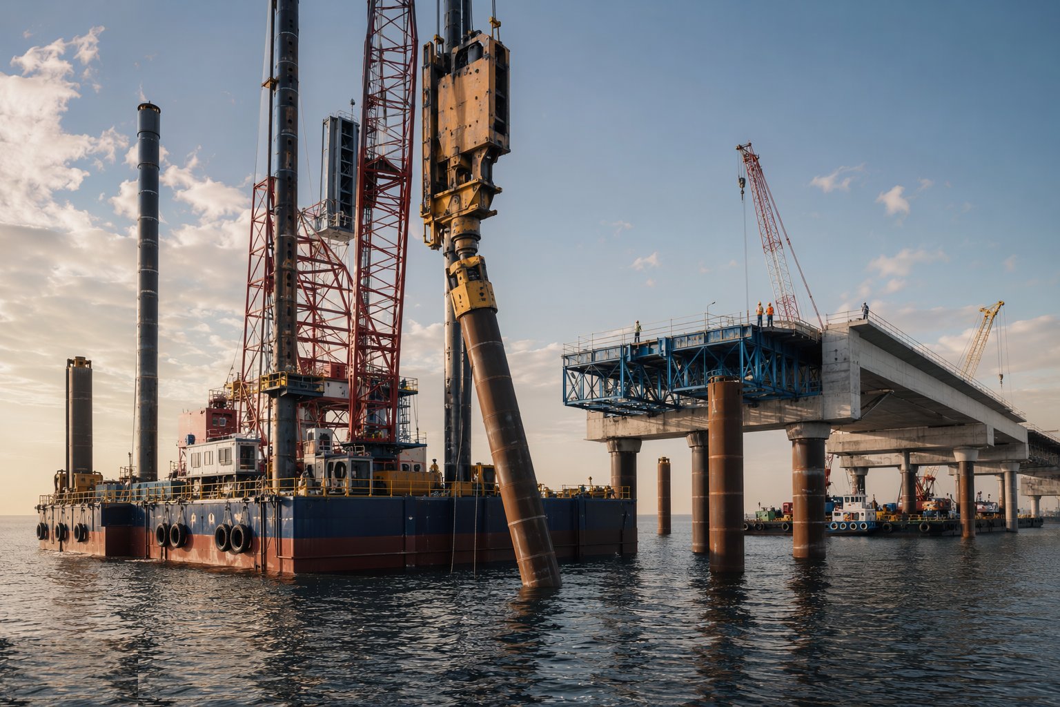
Tubes are lifted from the delivery barge, pitched into the leaders or the gate template at the designed rake, and set on the seabed with position and inclination verified before the hammer starts. Driving runs vibratory first where the ground allows, impact to finish, with the driving log recording penetration against blow count and the final set at design toe or refusal. Raked piles are checked for alignment continuously — a pile that wanders off line underwater cannot be argued back, and the correction options above water are all expensive.
Step 3: Extend, clean out and complete the piles
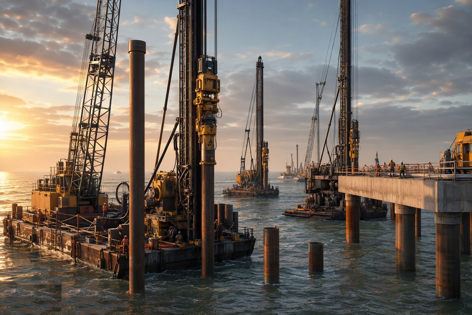
Where piles splice, sections are welded on between drives — full-penetration butt welds by coded welders, NDT per the specification — and driven on. Open-ended tubes are cleaned out to the required depth, reinforcement cages lowered where the design calls for them, and the concrete fill placed by tremie with the level controlled. Piles are cut off at level by burning, and every cut, weld and handling scar in the splash zone is cleaned back and recoated before the pile is allowed to call itself finished.
Step 4: Cap the piles and place the precast deck
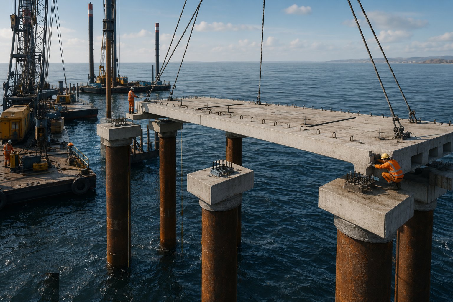
Pile caps and headstocks are cast in situ on formwork hung from the piles, or precast caps land direct on the cropped heads. Precast beams seat on the caps on their bearing strips, precast deck units span between with shear keys and starter bars projecting, and the in situ stitches and structural topping tie the assembly into one deck. Grouting of bearings and stitches is done with the tide in mind — material placed at low water gets a curing regime no laboratory intended.
Step 5: Build the dolphins, linkspans and furniture
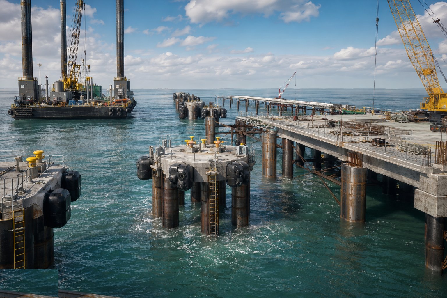
Dolphins are piled and capped as standalone structures with their fenders and bollards fitted, walkways lifted in to link them, and navigation lights and access ladders completed. Linkspan steelwork is erected with its articulation bearings, hydraulic or counterweight systems installed, and the ramp geometry commissioned against the tidal range and the vessels it will serve. The heavy ironmongery — fender panels, quick-release hooks, gangways — is set and torqued with the same discipline as the quay wall furniture it resembles.
Step 6: Fit the corrosion protection
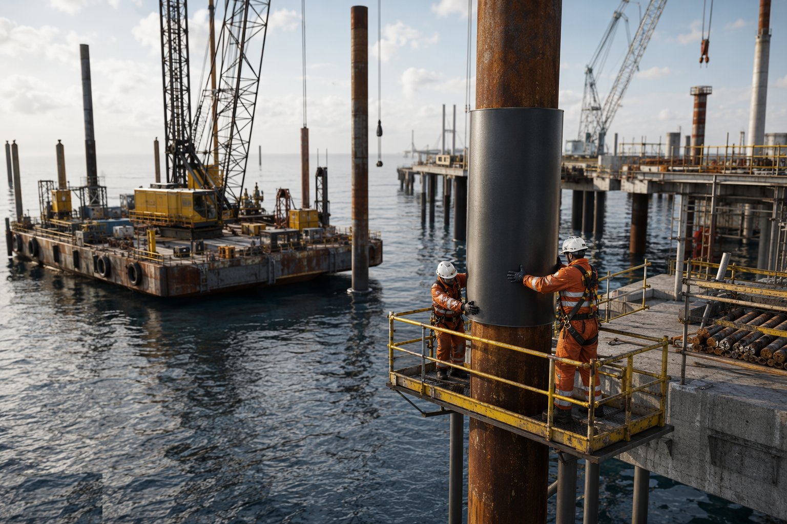
The structure's defence is commissioned before handover: coatings inspected and made good at every site weld and cut edge, sacrificial anodes welded on to their zones or the impressed-current system installed, energised and its potentials logged. Baseline potential readings are taken along the structure — the first entry in a corrosion logbook the operator will keep for decades — and any damage from construction plant is repaired now, while the barges are still here to reach it.
Step 7: Test, survey and hand over
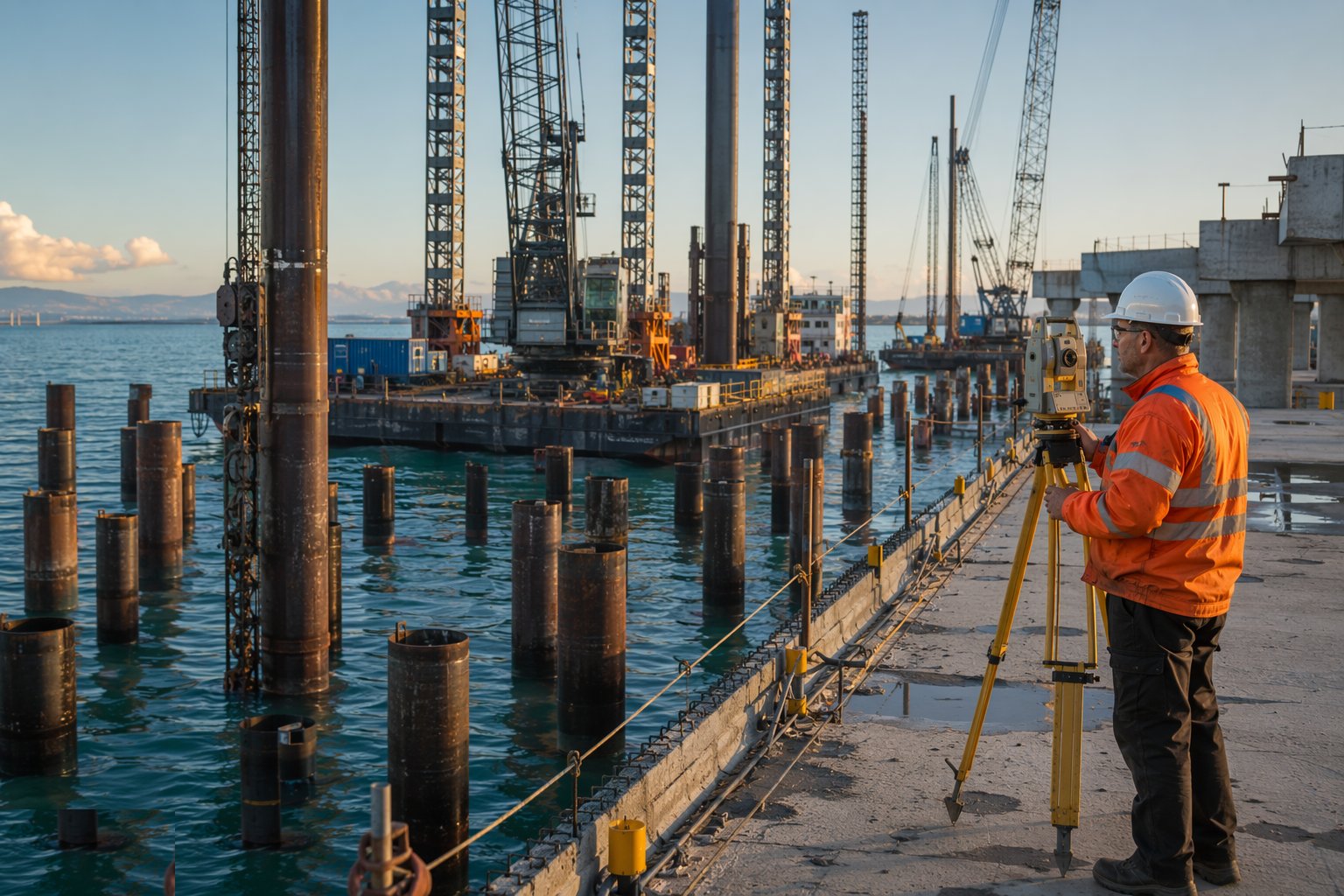
Final acceptance assembles the evidence: pile driving records and any dynamic or static load tests, weld NDT, coating and cathodic protection readings, deck bearing and stitch records, and the as-built survey of every pile position and deck level. Load testing of berthing and mooring points is witnessed where specified. The file goes to the port with the maintenance requirements written plain — anode inspection intervals, coating touch-up regimes — because a marine structure handed over without its defence manual is a structure already being lost.
Plant and equipment
- Piling barges with leaders, and jack-up platforms for stable precision work
- Vibratory hammers and hydraulic or diesel impact hammers sized to refusal criteria
- Floating cranes for pitching piles and placing precast units
- Gate templates and piling frames for position and rake control; RTK GNSS positioning
- Welding spreads, coded welders and NDT kit for pile splices; burning gear for cut-offs
- Tremie concrete supply by pump or skip for pile infill
- Work boats, safety boats and crew transfer vessels; tide and weather monitoring
- Cathodic protection installation and test equipment — reference electrodes and potential logging
Quality control checks
- Pile driving logs with hammer energies, sets and refusal records for every pile
- Position, verticality and rake surveys as-driven against tolerance — recorded before the barge moves
- Weld NDT records on splices and site joints; coating dry-film thickness checks in the splash zone
- Concrete infill and stitch records: cubes, levels and tremie logs
- Cathodic protection commissioning readings — baseline potentials logged for the operator's logbook
- As-built survey of every pile and deck level, with dynamic or static load test results where specified
Safety considerations
- Man-overboard as the standing risk: buoyancy aids worn, safety boats on station, recovery drilled
- Lifting from moving decks: lift plans that respect barge motion, sea state and the tag-line discipline
- Pile driving hazards: dropped objects from leaders, hammer energy and noise, exclusion zones enforced
- Tidal access: work fronts that flood, egress routes that close, and a daily plan written around the tide tables
- Welding and burning over water with fire watch and containment; hot work permits that mean it
- Weather windows and demobilisation triggers agreed in advance — the sea does not attend progress meetings
Common defects
- Piles out of position or rake beyond tolerance at cut-off — the deck geometry pays for it
- Refusal above design toe in obstructions or dense lenses, triggering redesign or pre-drilling
- Cut edges and site welds left unprotected in the splash zone — corrosion with a two-year fuse
- Precast bearings mis-seated or grouts incomplete — deck units rocking under the first crane
- Stitch concrete placed against a rising tide — washed cement and permanent honeycombing
- Anodes omitted, mis-zoned or damaged by construction plant — the protection that exists only on the drawing
Best suited for
- Tanker, bulk and LNG jetties standing in deep open water
- Ferry and ro-ro berths with linkspans and dolphins
- Access trestles carrying pipelines, conveyors and roadways to offshore structures
- Berth and mooring upgrades where wall construction is impossible
How long does Marine Piling & Jetty Construction take?
Typical duration: A 200–300 m piled jetty with dolphins and deck is a 9–18-month marine campaign, gated by weather windows and tidal working; long trestles run at production rates of a bent or two per week, and winter exposure is the variable every honest programme names..