Stadium Construction
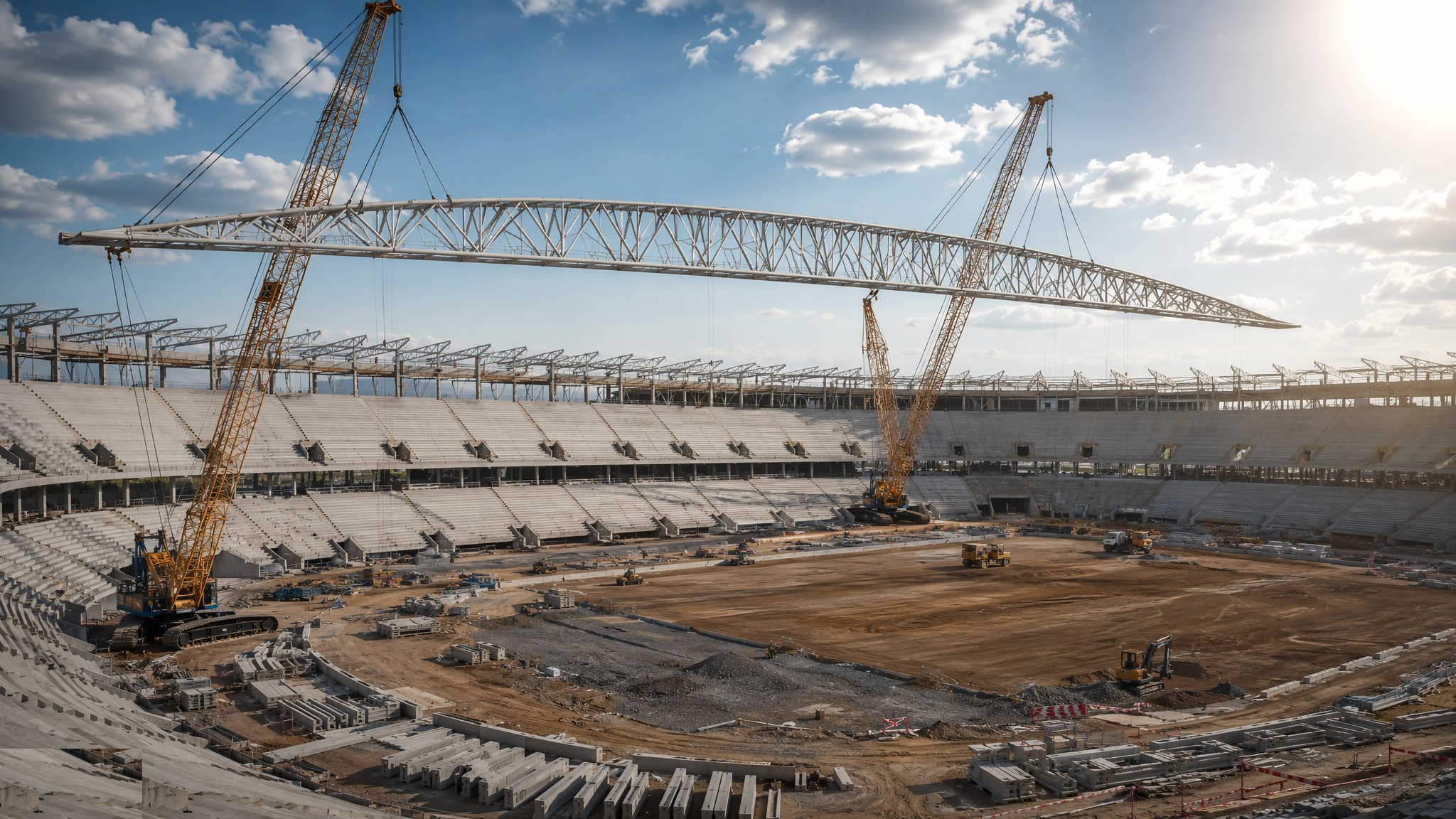
The specialist anatomy of a stadium: a raked bowl of precast terracing threaded with vomitories, capped by a long-span roof assembled on the ground and lifted in pieces too heavy for ordinary cranes.
Last updated 2026-07-28 by the BuildPedia Editorial Team.
What is Stadium Construction?
Strip away the hospitality boxes and the big screens and a stadium is two specialist structures married together: the bowl and the roof. The bowl is a precast concrete machine repeated hundreds of times — raker beams springing off the frame, stepped L-shaped terrace units spanning between them, each row of seats set by a sightline calculation, not by a bricklayer's eye. That calculation is the C-value: the vertical clearance, in millimetres, from a spectator's eye over the head of the person in front to the point of play. Around 60 mm is a minimum, 90 mm is considered good, and 120 mm is premium — and every millimetre of it is fixed the day the terracing geometry is cast, because you do not adjust a raked concrete bowl afterwards.
The roof is where stadium construction stops looking like building work and starts looking like heavy lift engineering. Spectator sightlines forbid columns inside the bowl, so the roof cantilevers — typically 30 to 60 m of steel truss reaching in from the perimeter frame, sometimes propped back by masts and cables. Sections that size cannot be lifted piecemeal at height, so they are preassembled: whole truss lengths welded and bolted together on the pitch or on the apron beside the stadium, painted and pre-fitted with purlins and services, then lifted as units of 100–400 t by crawler cranes of 600–1000 t capacity, or strand-jacked up from below when the craneage cannot reach. Until the ring closes and the bracing locks in, the roof is a temporary works problem hanging over several thousand future seats.
The third specialist thread is time. Stadia are built to immovable dates — a season opener, a tournament, a ceremony — and they are often built around or alongside a venue that keeps operating. That drives capacity phasing: completing and opening stands in sections, protecting the pitch under proprietary cover systems while cranes work over it, and designing in from day one the interfaces that event overlay will need — broadcast compounds, temporary power routes, hospitality fit-out zones — so that handing a building over to an event operator does not mean rebuilding half of it.
When and why is Stadium Construction used?
Stadium construction begins once the frame and lower concourses are underway, and it runs as a specialist package inside the main works rather than after them. It earns its keep because the bowl, the roof and the opening date each punish error in ways ordinary buildings do not. A terrace unit cast 15 mm out of line is a trip lip between rows for fifty years; a sightline model set out carelessly is a column of restricted-view seats nobody can sell; a roof lift planned on optimism is a 300-tonne truss hanging in the wind with nowhere to go. And because the opening fixture cannot slip, the programme has no float to hide mistakes in — which is why stadium work is run on preassembly, trial fits, survey control and rehearsal, not on improvisation at height.
Types of Stadium Construction
Precast terrace units on raker frames
The default bowl: factory-cast L- or Z-profile units, typically 6–8 m long, craned onto inclined raker beams and stitched with grouted joints and in-situ landings. Dimensional quality is set in the factory moulds; on site the game is landing them to line, level and step height so rows run true around the whole bowl.
Cast in situ terracing
Terracing poured in place on stepped formwork — slower and hungrier for labour, but used where precast logistics are impossible, where geometry is one-off, or on smaller stands in markets without a precast supply chain. The risk moves from the mould to the formwork: steps cast off a sagging deck give you wavy rows and ponding treads.
Cantilevered long-span steel roofs
Great triangulated trusses or box girders cantilevering 30–60 m over the seating from the perimeter frame, back-stayed to masts or held by the frame's own weight. The structural romance of the sector — and the reason the lifting, temporary stability and connection quality chapters of the method statement run to a hundred pages.
Cable, tension and fabric roof systems
Roofs hung from compression rings, cable nets or arch-and-cable systems, often carrying fabric or cushion cladding. Light, elegant and utterly unforgiving of geometry error: a tension roof only works at its designed shape, so every cable length, node position and jacking sequence is engineered, measured and recorded.
Retractable roofs and moving elements
Opening roof panels, sliding pitch trays and demountable seating — buildings with machinery in them. Rail alignment, drive systems, control integration and years of maintenance access are designed in from the start; the construction task is as much precision mechanical installation as it is structure.
Stadium Construction: step by step
Step 1: Set out the bowl from the sightline model
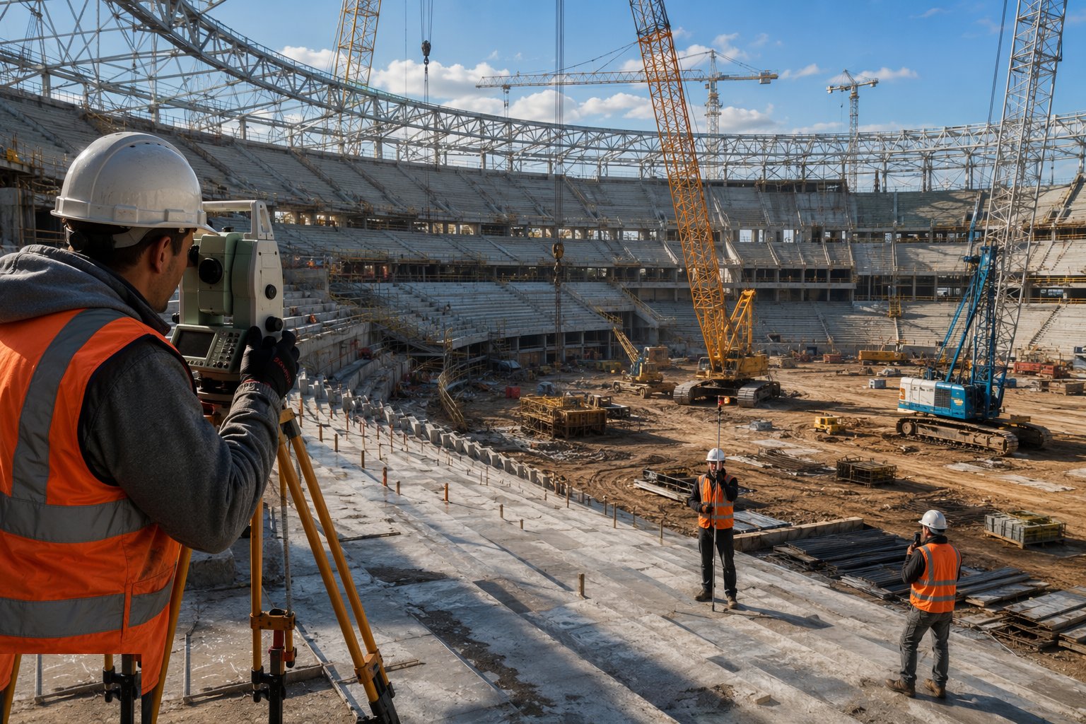
Everything starts with the geometry file: the seating bowl derived from the sightline model, row by row, translated into setting-out data for every raker beam bearing and terrace unit seat. Primary control is established around the stadium and checked religiously, because a bowl is a closed ring — errors accumulate around the circle and arrive at the last bay as a gap that will not close or a step that does not meet its neighbour. The surveyor's job is not just position but the vertical story: each row height is checked against the C-value calculation, because the people who will sit in row 47 are trusting that the person in row 46 will not block their view, and that trust was earned or lost with a total station.
Step 2: Erect the bowl frame and raker beams
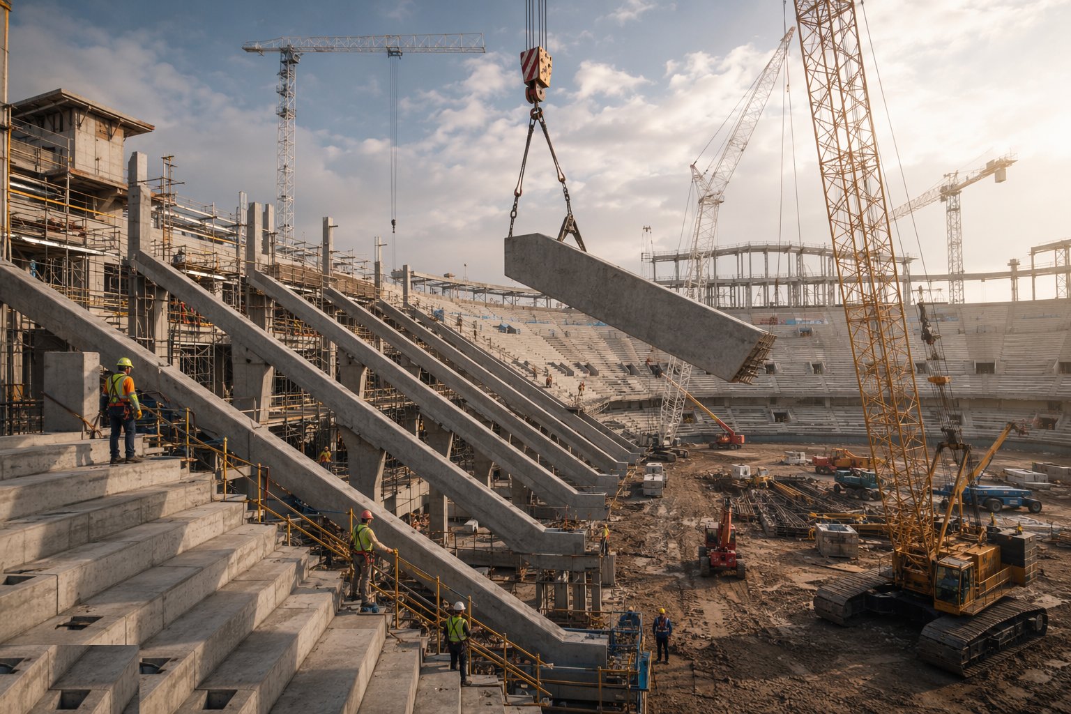
The bowl frame goes up in sectors, and the raker beams — the inclined spine members that carry the terracing — are its critical components. Precast rakers are craned onto prepared bearings, propped until the stitch concrete and bracing lock them into the frame; steel rakers are bolted up and surveyed before the terracing follows. Bearings are set to exact level because the terrace units have almost no adjustment: the raker is the datum, and if the raker is wrong the whole rake of seats above it is wrong with it. Temporary propping and bracing follow the temporary works design until each sector is self-stable — an unbraced run of rakers is a line of dominoes on a slope.
Step 3: Install the precast terrace units
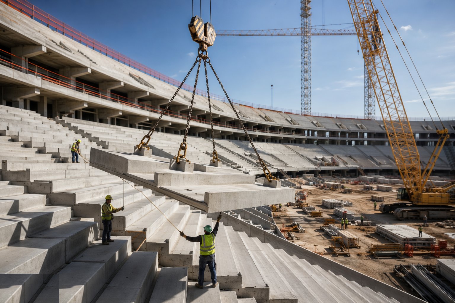
Terrace units arrive in delivery sequence matched to the erection plan — this is just-in-time work, because a stadium footprint has nowhere to store a thousand concrete steps. Each unit is craned in, landed on the rakers, aligned to the setting-out marks, and levelled on its bearings before the grout and stitch joints are made. The checks that matter are the ones the crowd will feel: step height consistency between adjacent units, line of the nosing along the row, and no lips or rocking units underfoot. A gang in rhythm can place twenty or thirty units a day; a gang fighting out-of-tolerance bearings places five and generates a defect list.
Step 4: Form vomitories, gangways and barriers
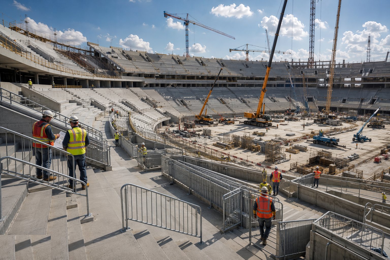
The bowl is cut through by its circulation: vomitories — the openings through which spectators pour in and out — radial gangways, lateral walkways, staircases and the barrier lines fronting each tier. These are life-safety elements with dimensions fixed by the crowd design and the licensing guidance (in the UK, the Green Guide — the Guide to Safety at Sports Grounds): widths, capacities, sightline-preserving barrier heights, and structural barriers designed for crowd loading, not just a leaning adult. Precast vomitory walls and stair flights are fitted into the bowl geometry, and every width is verified as built, because the safety certificate is issued against measured capacity, not against the drawing.
Step 5: Preassemble the roof at ground level

The roof is built where the welders and fitters can stand on the ground. Truss sections are assembled on trestles set to the designed camber, connections completed and verified, purlins, walkways, lighting gantries and as much MEP as possible pre-fitted — every bolt tightened at grade is a bolt not tightened from a MEWP sixty metres up. Assembly geometry is checked against the model with laser trackers or total stations, because a truss assembled to the wrong camber will not meet its neighbour in the air. Trial fits of critical splices are done here too; the first time two 200-tonne sections meet should not be at the hook of a crane in a crosswind.
Step 6: Make the big lifts — cranes or strand jacks
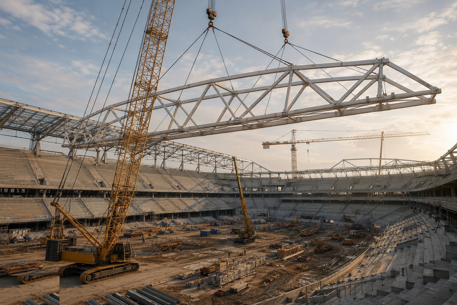
Lift days are the stadium's public theatre and its private agony. Each lift is an engineered operation: the crane configuration and ground bearing checked (crawler cranes of 600–1000 t capacity need prepared, verified hardstanding), the rigging designed, the centre of gravity calculated, the tag lines rigged, the wind limit set and watched. Where the roof geometry or the bowl defeats craneage, strand jacks lift sections vertically from below, climbing them up on steel cables a few hundred millimetres per stroke. Sections are landed on their bearings, pinned or bolted to the minimum stable condition, and surveyed before the crane unhooks — and the temporary works sequence holds the growing roof stable until the ring finally closes and the structure can look after itself.
Step 7: Close out, commission and open in sections
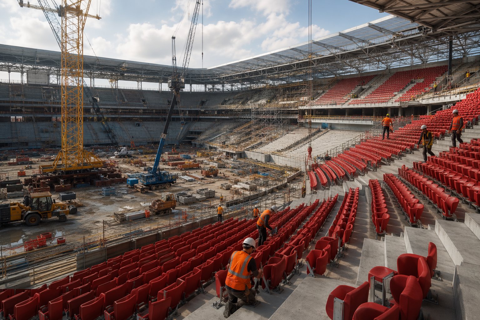
Completion is phased to the opening date: sectors of the bowl handed over, inspected and licensed while other sectors are still worksites, with hard physical separation between the two. Seating goes on last — tip-up seats fixed to the terrace nosing rows the surveyor set out months earlier — followed by bowl finishes, signage, turnstiles and the broadcast and event overlay infrastructure. The pitch itself is protected through the works with cover systems and only uncovered for its final grow-in or surface certification. The last surveys close the file: as-built bowl geometry, barrier and gangway widths for the safety certificate, and roof deflection readings under load, so the operator inherits a structure with a known shape and a measured capacity.
Plant and equipment
- Crawler cranes of 600–1000 t capacity on engineered hardstanding for roof lifts
- Strand jack systems with hydraulic power packs and control cabins
- Tower cranes and telehandlers for terrace unit and frame erection
- Assembly trestles, temporary propping towers and bracing for the roof build-up
- MEWPs and roof access systems for connection and cladding work at height
- Total stations, laser trackers and GNSS for bowl geometry and lift positioning
- Pitch protection cover systems (terra-type tile decking) for work over playing surfaces
- Torque and tensioning equipment for pre-loaded roof connections
Quality control checks
- Sightline verification: row-by-row as-built survey against the C-value model before seats are fixed
- Precast terrace unit dimensional records and bearing surveys — line, level, step height and joint width
- Roof assembly geometry checks against the model at trestle level, with laser tracker records
- Weld procedure approvals, welder qualifications and NDT records on roof splices and nodes
- Bolt installation audits on pre-loaded connections; torque or part-turn verification logged
- Vomitory, gangway and barrier as-built widths and load test records for the safety certification
- Lift-by-lift engineering sign-offs: rigging certificates, ground bearing verification, crane configuration checks
Safety considerations
- Heavy lifting operations: appointed person control, engineered lift plans, exclusion zones and hard wind limits — a 300 t truss does not forgive a gust
- Work at height over raked bowls: edge protection on terrace fronts, fall-arrest only where collective protection cannot go, and controlled access to open risers
- Dropped objects down the rake: tool lanyards, netted or boarded zones below upper-tier works, and no stacked materials on terrace steps
- Temporary stability of the incomplete roof: no lift stage left without its designed bracing, props or ties, and no unhooking until the minimum stable condition is confirmed
- Public interface on sectional openings: hard barriers, separate access routes and stewed coordination between crowd operations and the construction site
- Ground conditions under crawler cranes: verified hardstanding, outrigger or track bearing checks, and no crane moves over unproven ground
Common defects
- Terrace units out of line — trip lips between adjacent units and wandering nosing lines that no amount of snagging paint will hide
- Restricted-view seats from setting-out drift or an unplanned column, discovered at the first sell-out fixture
- Ponding on concourses and terrace treads where falls were lost in the casting or the stitch joints
- Roof deflection beyond the predicted values, showing up as cladding fit problems and ponding roof zones
- Vomitory or gangway widths short of the licensed capacity — a safety certificate problem, not a snag
- Corrosion at exposed roof connections and mast bases where drainage and protective systems were an afterthought
Best suited for
- Major stadia and arenas where bowl geometry and long-span roofs dominate the build
- Grandstand construction and stand-by-stand expansions of existing grounds
- Projects with immovable opening dates needing sectional completion and capacity phasing
- Venues that must keep operating while construction continues around or above them
How long does Stadium Construction take?
Typical duration: A new 20,000–60,000-seat stadium typically runs 24–36 months; a single grandstand 9–15 months; roof lift campaigns are measured in a handful of high-stakes days inside a year of preassembly..