Radiation Shielding & Imaging Suites
Lead-lined walls for X-ray and CT, Faraday cages and quench pipes for MRI, and two-metre concrete bunkers for linear accelerators — the invisible engineering that keeps radiation in and interference out.
Last updated 2026-07-28 by the BuildPedia Editorial Team.
What is Radiation Shielding & Imaging Suites?
Imaging and radiotherapy rooms are the only rooms in a hospital where the walls themselves are clinical equipment. A CT scanner, an X-ray room or a linear accelerator produces ionising radiation that must be attenuated before it reaches the corridor, the ward above or the office next door; an MRI scanner produces a magnetic field that distorts every image if the room is not electrically quiet and mechanically stable. The shielding is designed by a Radiation Protection Adviser (RPA) from the equipment's workload and scatter data, specified as lead equivalence or concrete thickness, and then built, tested and signed off before the machine is ever switched on. It is construction work with a physics exam at the end.
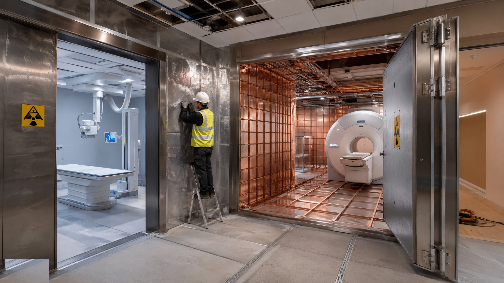
The construction splits three ways. For diagnostic X-ray and CT rooms the shielding is lead: sheet lead bonded to plasterboard or plywood backing, or lead-lined proprietary panels, built into walls, doors, frames and viewing windows, with every joint, penetration and junction lapped so there is no leakage path — a single unshielded screw hole through a lead wall is a radiation leak. For MRI suites the problem is different: the magnet's field must be contained (steel or shielding to control the fringe field), the room must exclude radio-frequency interference (a welded copper or galvanised-steel Faraday cage with RF doors and filtered penetrations), and the magnet must be able to shed its cryogens in a quench — a dedicated quench pipe, sized and routed to atmosphere, that a builder must never reduce, kink or "value-engineer". For radiotherapy, the answer is mass: linear accelerator bunkers are cast in situ concrete boxes with primary barrier walls commonly around two metres thick and mazes that let staff in without letting neutrons and scattered radiation out.
The regime around the build is as specialist as the build itself. Lead work is done by trained installers under hygiene controls — it is a toxic material handled all day. The RPA or a medical physics expert verifies the finished shielding with leakage surveys and dose measurements before clinical use, and the Faraday cage is tested for RF attenuation to the scanner manufacturer's specification. In the UK the Ionising Radiations Regulations 2017 (IRR17) and HSE oversight govern; in the UAE the Federal Authority for Nuclear Regulation (FANR) licenses radiation facilities and its requirements drive the same discipline — shielding calculated, built, verified and documented before a single patient scan.
When and why is Radiation Shielding & Imaging Suites used?
Radiation shielding lands late in the programme but early in the planning: the bunker or lead-lined shell is built with the structure and finishes, the RPA's shielding calculations are frozen before the room layouts are, and the scanner and linac manufacturers' installation requirements — floor loads, quench routes, RF environments — are embedded in the design from day one. It matters because shielding defects are invisible until the physics survey finds them, and the fixes are brutal: a lead wall that leaks means stripping finishes back to the structure; a Faraday cage that fails its attenuation test can mean re-welding panels inside a finished room; a bunker that underperforms cannot be patched with paint. The verification survey is a hold point that clinical commissioning cannot pass without, so the shielding trade effectively holds the keys to the opening date of the imaging department.
Types of Radiation Shielding & Imaging Suites
Lead-lined shielding (X-ray, CT, fluoroscopy)
Sheet lead of specified thickness (typically 1–3 mm, Code-equivalent lead equivalence stated by the RPA) bonded to plasterboard or plywood, or factory-made lead-lined boards and panels. Every joint is lapped with lead fillets or battens, penetrations are backed with lead discs, and doors, frames and viewing windows are supplied as tested leaded units.
MRI Faraday cages and magnetic shielding
A continuous conductive enclosure — soldered copper sheet or galvanised steel panels — around the scan room, with RF-sealed doors, filtered electrical penetrations and waveguide vents, attenuating radio-frequency interference to the scanner maker's figure. Where the fringe field threatens adjacent areas, magnetic shielding in steel plate or specialised materials supplements the cage.
Quench pipe systems
The safety vent from the MRI magnet to open atmosphere: a dedicated, typically stainless-steel pipe sized to the magnet manufacturer's figure, routed with minimal bends, insulated against cryogenic temperatures, and terminated clear of people and air intakes. In a quench the magnet's cryogens boil off in seconds — the pipe carries that event out of the building, and nothing else may share it.
Linac bunkers (high-density concrete)
Cast in situ concrete vaults for linear accelerators: primary barriers commonly 1.8–2.5 m of ordinary or high-density concrete, secondary barriers and an entrance maze designed to scatter radiation down to safe levels, with shielded doors — often neutron-attenuating borated or lead/steel composite doors weighing tonnes. Pours are planned as continuous mass-concrete operations to avoid joints through the barrier.
Shielded doors, frames and viewing panels
Factory-built shielded components that close the openings the walls cannot: lead-lined doors with continuous shielding into the frame and threshold, lead-glass or lead-acrylic viewing windows between control room and scan room, and RF doors with finger-stock seals for MRI. Each component carries a tested shielding rating that must match the wall it sits in.
Radiation Shielding & Imaging Suites: step by step
Step 1: Freeze the shielding design with the RPA

Before construction, the RPA produces the shielding calculations from the equipment type, workload projections, room occupancy factors and scatter geometry — output: required lead equivalence or concrete thickness for every wall, floor, ceiling, door and window. The drawings are marked up barrier by barrier and issued as a controlled set; every trade knows which walls are shielded and what the rating is. Changing a room layout, a door position or an occupancy next door after this point is not a drawing revision — it is a recalculation, and it goes back through the RPA.
Step 2: Build the bunker or shielding substrate

For linac bunkers, cast the mass-concrete walls and roof as engineered pours: high-density aggregate where specified, continuous pours or designed joints kept out of primary barrier paths, formwork and falsework checked for the immense fresh-concrete pressures, and construction joints positioned where the physics allows. For diagnostic rooms, build the substrate true and level — shielding boards and lead sheet are unforgiving of twisted studwork — with all structural penetrations identified before lining starts, because drilling through finished lead is how leaks are born.
Step 3: Install lead lining with lapped joints
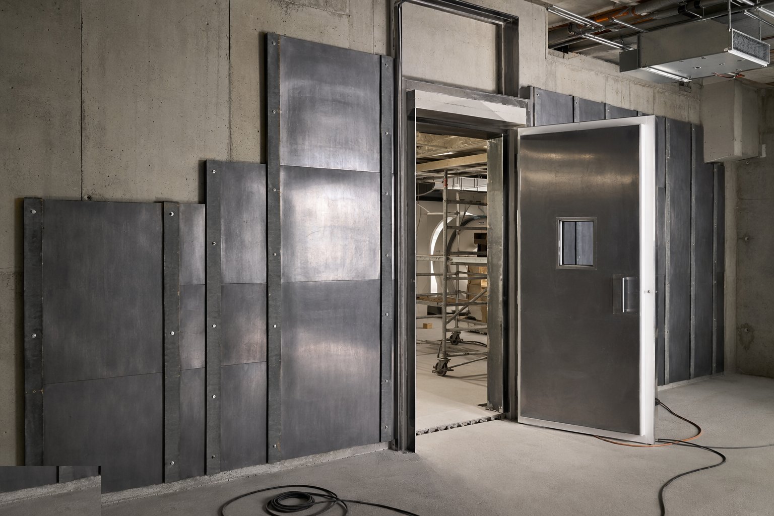
Fix lead-lined boards or apply sheet lead to walls, floors and ceilings to the specified thickness, working from the marked-up barrier drawings. Every board joint gets its lead fillet or batten of matching thickness; every penetration — sockets, pipes, fixings — gets a lead backing disc; every corner, floor junction and ceiling junction is lapped per the detail. Doors, frames and windows arrive as rated factory units and are installed complete — a site-modified lead door is an untested lead door. Hygiene discipline runs throughout: lead handling under controlled conditions, no eating or drinking in the work area, and waste lead disposed of as the controlled material it is.
Step 4: Build the MRI Faraday cage and quench route
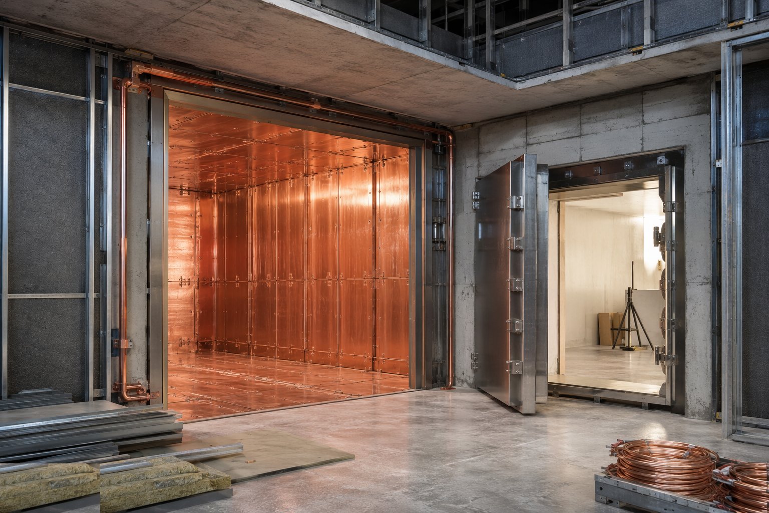
Erect the RF enclosure as a continuous conductive skin — panels or copper sheet fully soldered or clamped to the manufacturer's system, floor cage isolated from the building as designed, and the RF door hung and sealed. Every penetration passes through filters or waveguides: electrical feeds through RF filters, HVAC through waveguide vents, medical gases and data through approved penetration panels. Install the quench pipe as a dedicated run at full diameter, insulated, with the minimum possible bends, and prove its route to atmosphere before the magnet arrives — the scanner vendor will survey both the cage attenuation and the quench route before they energise, and they will walk away from either one that fails.
Step 5: Coordinate services through the shielding
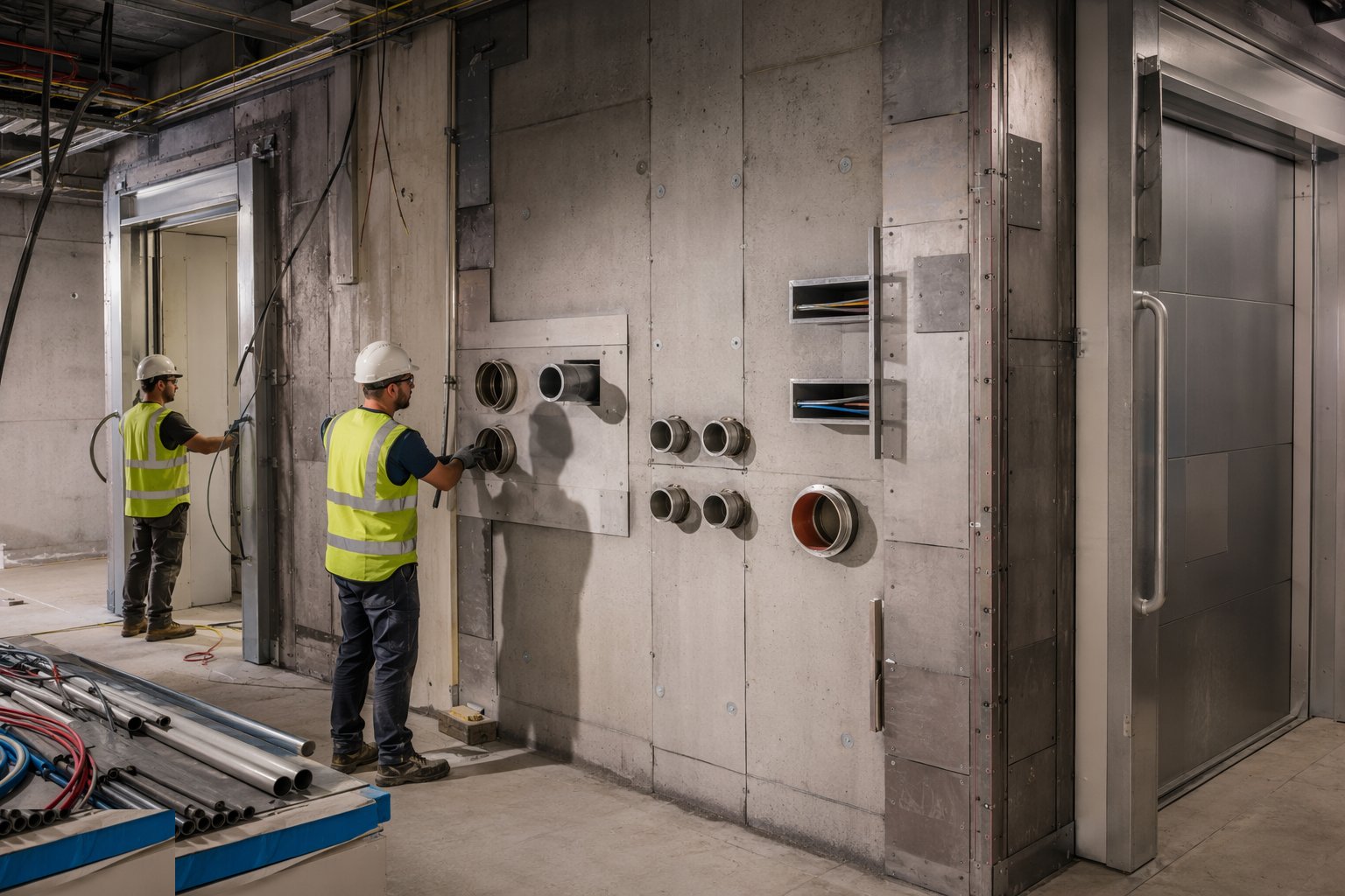
Every service that crosses a shielded barrier crosses it under control: penetrations detailed with the RPA, kept small, lapped or baffled so radiation cannot stream through, and fire-stopped without breaching the shielding logic. In MRI rooms, nothing ferromagnetic enters the specification — non-magnetic fixings, pipework and equipment within the controlled zone — and the floor slab is built to the magnet's load and iron-content limits, because a rebar cage full of steel in the wrong place distorts the magnet's homogeneity before it is even switched on.
Step 6: Verify the shielding by physical test
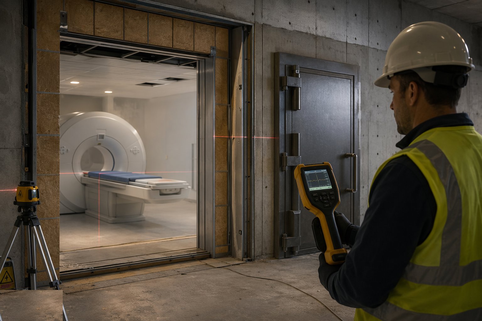
Before clinical use, prove the shielding does what the calculation said. For lead rooms, the RPA or medical physics team surveys every barrier with radiation leakage measurements under beam conditions; joints, doors, windows and penetrations get particular attention. For the Faraday cage, RF attenuation is tested to the scanner manufacturer's figure across the frequency band. For bunkers, dose surveys verify the maze and barriers once the linac is installed and operating. Every survey is documented — the shielding certificate is part of the licence to operate, and a failed survey means opening up the shielding, however finished the room looks.
Step 7: Document and hand over with the equipment

Compile the shielding file: RPA calculations, as-built barrier drawings, material certificates for lead and concrete, photographs of joints and penetrations before covering, test and survey reports, and the equipment vendor's acceptance. Hand the file to the trust with the room — future refurbishments will drill into these walls, and the record of what is inside them is a safety document for the life of the building. Any later modification to a shielded room goes back through the RPA, and that rule is written into the handover.
Plant and equipment
- Sheet lead, lead-lined boards and lead fillet/batten stock with cutting tools
- Proprietary RF cage panel systems, solder kits and RF doors
- Stainless-steel quench pipe sections, insulation and lifting gear
- Mass-concrete plant for bunker pours: pumps, vibrators and thermal controls
- Shielded door sets, lead-glass viewing panels and installation lifting equipment
- Radiation survey meters and dose measurement equipment (physics teams)
- RF attenuation test equipment for cage validation
- Lead-handling PPE, hygiene facilities and controlled-waste containers
Quality control checks
- RPA shielding calculations frozen and issued as controlled barrier drawings
- Lead thickness and lapping verified against the drawings before covering — photographed
- Every penetration through a barrier detailed, lapped and logged
- Faraday cage attenuation tested to the scanner manufacturer's specification
- Quench pipe diameter, route and termination proven before magnet delivery
- Post-construction radiation leakage and dose surveys passed and certified
Safety considerations
- Lead is toxic: controlled handling, hygiene regime, health surveillance and controlled waste disposal
- Mass-concrete bunker pours: formwork pressures, continuous-pour planning and thermal cracking control
- Heavy shielded components: lead doors and linac doors weigh hundreds of kilos to tonnes — planned lifting only
- MRI environment: strict non-ferromagnetic discipline near the magnet — projectile risk is lethal
- Cryogenic quench events: keep the quench route clear; never occupy or store along its path
- No energisation of radiation equipment until shielding verification and licensing are complete
Common defects
- Unlapped or short-lapped lead joints — leakage lines that only the physics survey finds
- Penetrations drilled after lining without lead backing — sockets and pipes as radiation windows
- Site-modified shielded doors or frames — the tested rating voided at the first hinge adjustment
- Faraday cage seams poorly soldered or the door seal damaged — RF interference that fails the vendor survey
- Quench pipe reduced in diameter, kinked or shared with another service — a life-safety defect discovered at vendor sign-off
- Construction joints cast through a bunker primary barrier — a weakness in the shielding that mass concrete cannot be patched over
Best suited for
- Diagnostic imaging rooms: X-ray, CT, fluoroscopy and dental suites
- MRI suites needing Faraday cages, quench systems and magnetic control
- Radiotherapy linac bunkers and brachytherapy rooms
- Nuclear medicine and PET facilities with hot-lab shielding
How long does Radiation Shielding & Imaging Suites take?
Typical duration: Diagnostic room lead lining: 2–4 weeks per room including verification. MRI cage and quench: 4–8 weeks. Linac bunkers: 2–4 months for structure alone, dominated by mass-concrete operations..