Hotel Structure & Envelope
Repetitive bedroom floors on a fixed room grid — concrete or steel frames, bathroom and room pods, a façade that repeats one window at a time, and the plant floors and back-of-house cores that make a hotel run.
Last updated 2026-07-28 by the BuildPedia Editorial Team.
What is Hotel Structure & Envelope?
A hotel is the most repetitive building in the commercial world. One bedroom module — typically 3.6–4.2 m wide — repeats along every corridor, floor after floor, and the structure is designed around that repetition: a concrete frame with flat slabs in most UK and Gulf hotels because mass gives you acoustic separation between rooms for free, or a steel frame with composite deck where speed and weight win, with the room partitions doing the acoustic work instead. The grid is fixed early and defended fiercely, because everything downstream — pods, façade panels, MEP distribution, FF&E — is procured as a multiple of the room, and a grid that drifts turns a production line back into a building site.
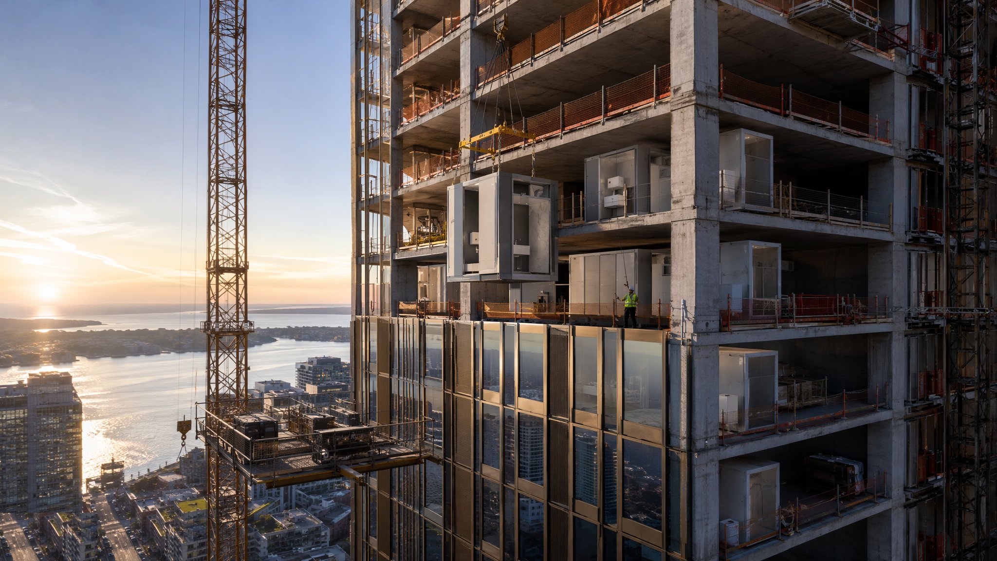
Modular construction has changed how the repetitive part gets built. Bathroom pods arrive fully fitted — tiled, plumbed, wired, tested at the factory — and are craned in and connected to risers in hours; full volumetric room modules go further, stacking complete bedrooms on a podium or a steel chassis. Neither removes the discipline: pods demand setting-out tolerances measured in single millimetres, hoisting routes and weather windows planned like lifts of structural steel, and riser connections that land exactly where the factory put the tails. Get the structure right and the pod installer is a delivery service; get it 15 mm wrong and every pod on that floor is a site modification.
The envelope is the room grid drawn on the outside of the building: one window per room (or per bay), a punched or unitised façade repeating at the structural module, with the jambs, cills and fixing zones built into the frame as it rises. Plant floors sit where the engineer can reach them — roof plant for chillers and AHUs, sometimes a mid-level plant floor on tall towers — and the back-of-house core is a building within the building: goods lifts, service corridors, laundry chutes, risers and the kitchens and plant that guests must never hear. In the Gulf the envelope carries the cooling battle too: solar-control glazing, high-performance build-ups to satisfy Al Sa'fat or Estidama, and structure that shrugs off chloride-laden coastal air.
When and why is Hotel Structure & Envelope used?
The structure and envelope follow the substructure and lead everything, because the fit-out production line cannot start until floors are complete, weathertight and dimensionally trustworthy. Concrete flat-slab frames are chosen where acoustic mass, fire robustness and local concrete economics dominate — the Gulf tower vernacular and much UK mid-rise hotel work; steel and composite decks where programme and foundation load argue for dry, light construction; pods and modules where repetition, quality and labour scarcity make factory building pay. The room grid is defended because it is the hotel's unit of account: keys per floor, façade panels per floor, pods per floor, minutes per room in the fit-out programme. A frame that respects the grid feeds a production line; one that wanders forces every following trade to measure every room — and a 300-room hotel measured one room at a time is a programme you have already lost.
Types of Hotel Structure & Envelope
Cast in situ concrete frame with flat slabs
Columns and flat slabs — often post-tensioned on wider grids — poured floor by floor on a weekly or fortnightly cycle. The default for mid- and high-rise hotels: acoustic mass between rooms built into the structure, robust fire performance, and the Gulf's structural vernacular.
Steel frame with composite deck
Steel columns and beams on the room module with metal-deck composite slabs, braced or core-stabilised. Faster and lighter than concrete, common on UK mid-market brands — but acoustic and fire performance must be added back with boards, screeds and resilient layers rather than coming free with the frame.
Bathroom pods on a conventional frame
A concrete or steel frame with factory-finished bathroom pods craned in floor by floor and connected to risers. The dominant hybrid: keeps the frame's flexibility, takes the wet trades off site, and makes riser accuracy the site's most important tolerance.
Full volumetric room modules
Complete bedroom-and-bathroom modules factory-built and stacked on a podium, concrete core or steel chassis, with corridors and risers built conventionally between them. Fastest on paper and best on factory quality — but transport sizes, cranage and module-to-module tolerance control rule the design from day one.
Podium-and-tower hotel structures
A transfer podium carrying the bedroom tower above ballrooms, restaurants and back-of-house at ground levels, with plant floors and a BOH core rising through. The full-service hotel arrangement: two structural logics — long-span below, repetitive above — stitched together at the transfer level.
Hotel Structure & Envelope: step by step
Step 1: Lock the room grid and the structural module
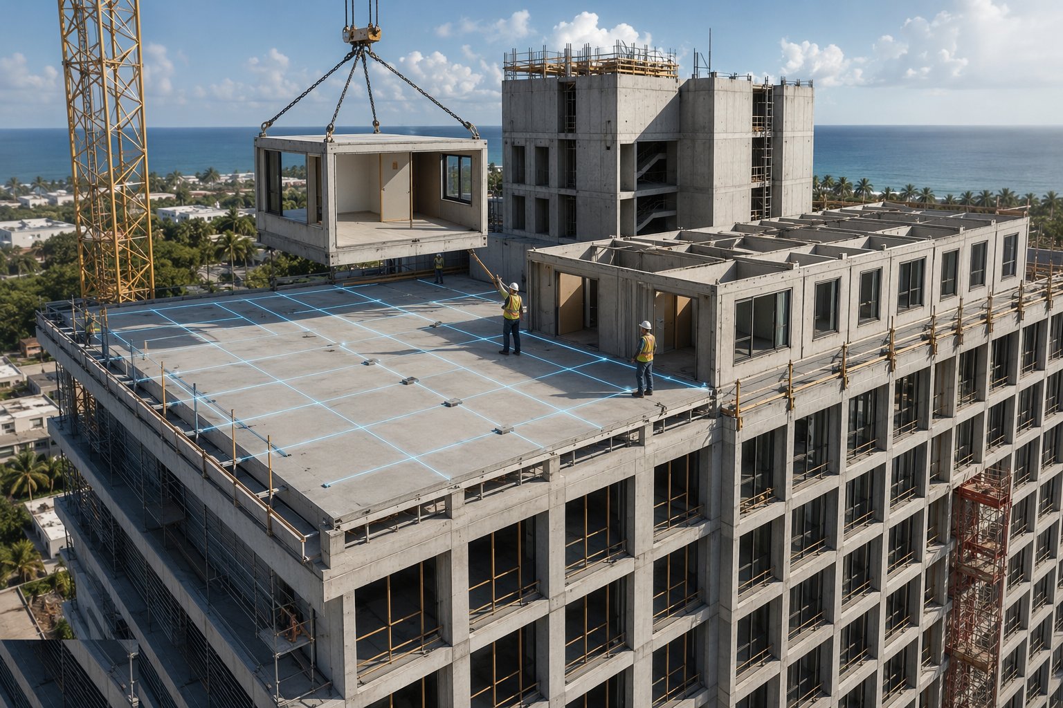
The room module is fixed with the operator's brand standards in one hand and the structural engineer in the other: room width, structural grid, slab depth and soffit zones for services, corridor widths, riser positions and the pod or façade module that everything will repeat. This is a commercial freeze as much as a design one — the brand's room matrix, the façade panel count, the pod procurement and the fit-out rate all price off this grid. Once frozen, it is defended through every design review, because a value-engineering tweak to the grid at month six re-opens the pod order, the façade contract and the FF&E schedule at month six prices.
Step 2: Build the frame on the repeating cycle
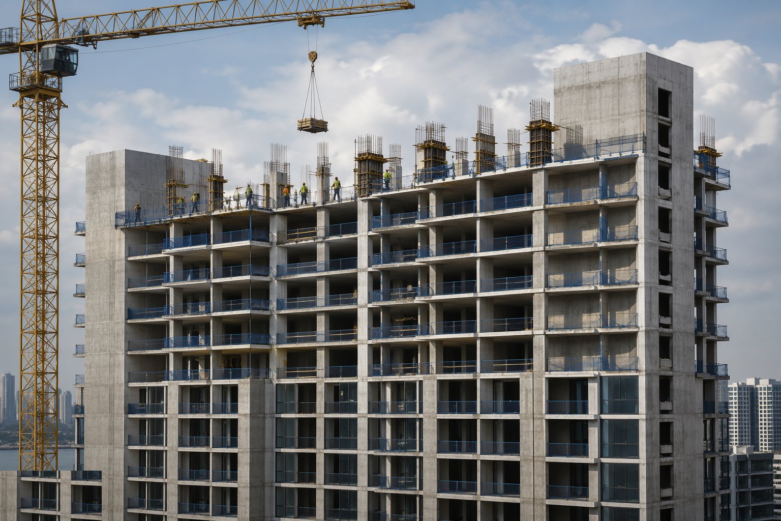
Concrete frames climb on table forms with back-propping designed for the pour cycle above, post-tensioned slabs stressed and released to programme, columns and shear walls plumbed against survey control floor by floor. Steel frames erect bay by bay to the method statement with decking following immediately behind. Either way, the discipline that matters is repetition with accuracy: edge of slab to line, column positions within tolerance, kickers and couplers right at every level — because the fit-out will not survey each room, it will assume each room, and it will bill you for every assumption you broke. Geometry is checked per floor and issued to the façade and pod teams as their working datum.
Step 3: Form the cores, BOH and plant floors
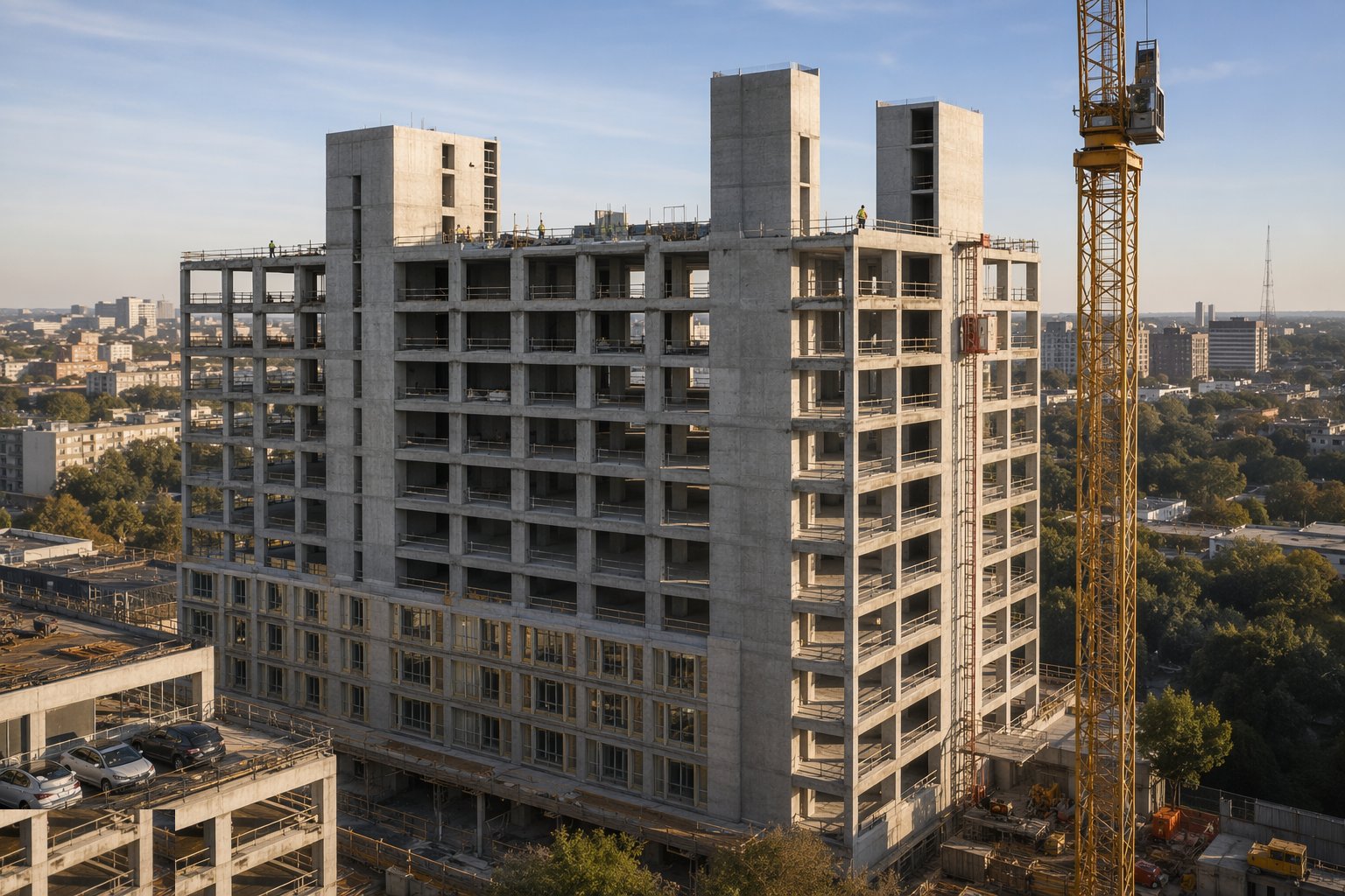
Guest and goods lifts, stairs, risers and service cores are built ahead of or with the frame — jump-formed or conventional — with the openings and embedments schedule policed per lift, because a forgotten cast-in in a core wall is a diamond-saw variation. Back-of-house floors get the structure their kit demands: plant floor slabs checked against chiller and AHU loads with plinths and inertia bases cast in, laundry and kitchen areas with the drainage falls, kerbs and floor build-ups formed as the slab pours, and goods lift shafts with the pit depths and overtravel the lift schedule needs. Plant floors on tall towers are structural floors, not afterthoughts — the cooling load of a Gulf hotel hangs a small power station on its roof.
Step 4: Set the façade rhythm into the frame
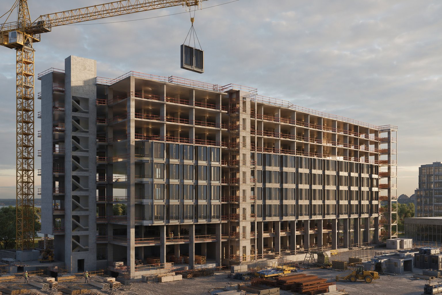
The façade's fixing zones are built as the frame rises: edge-of-slab positions, cast-in channels or brackets for unitised panels, opening jambs and cills formed true for punched windows, and balcony upstands, balustrade fixings and drainage formed with the slab — not drilled into it later. Openings are surveyed against the room grid per floor, because the façade fabricates to the grid and the glazier's adjustment range is the only forgiveness in the system. In the Gulf, the envelope build-up — solar-control glazing, insulated spandrels, cladding listed under the UAE Fire and Life Safety Code — is approved as a system with Civil Defence before fabrication, and the frame's accuracy is what lets that system fit as tested.
Step 5: Design in the pods: structure, hoisting and connections
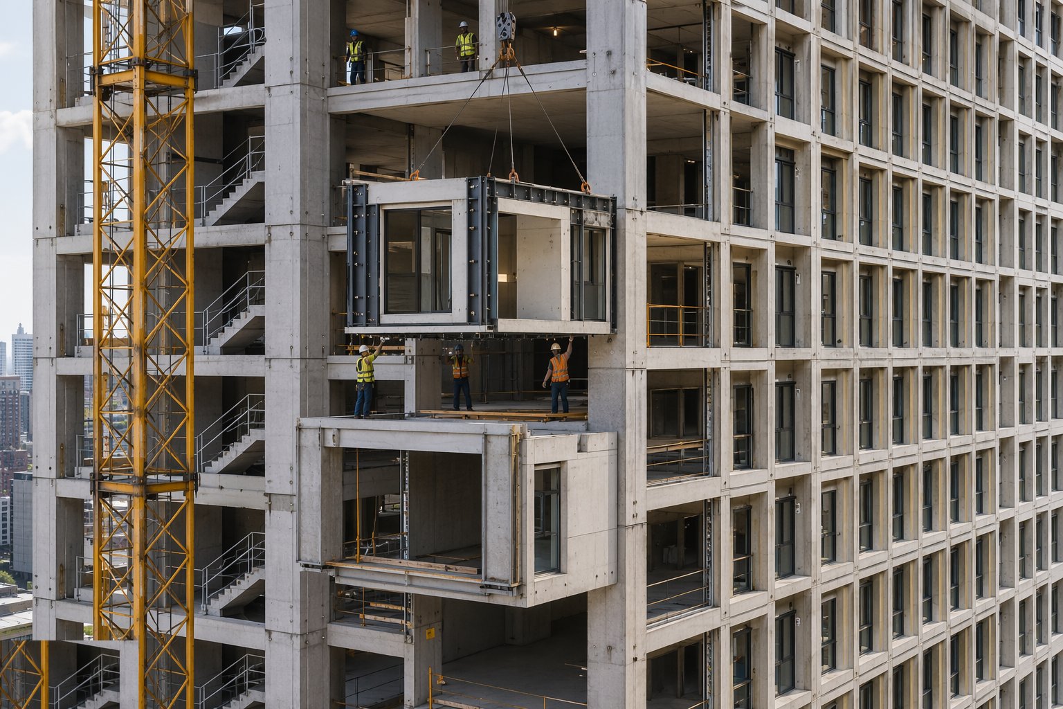
Pod installation is a lifting and tolerance operation, not a finishing trade. Slab set-down zones are cast to the pod manufacturer's level and flatness tolerances, riser tails and drainage drops are positioned to land on the factory connections within millimetres, and the hoisting route — crane position, load radius, weather limits, floor-by-floor loading sequence — is planned before the pod order is signed. Pods arrive wrapped, are landed on their set-downs by crane or skated in through a temporary opening, positioned, and connected by a specialist gang working floor by floor behind the frame. Every connection is tested as it is made, because a leaking pod joint found after the ceiling closes costs a ceiling, a pod strip-out and a floor's programme.
Step 6: Close the envelope weathertight
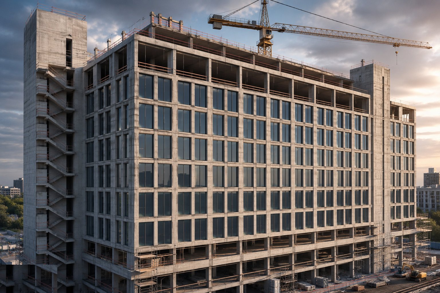
Windows or unitised panels install floor by floor behind the frame, with air, water and wind performance to the tested system standard — CWCT discipline on curtain walling, site hose testing on punched openings where specified — and the roof completed with its falls, upstands and plant kerbs proven against the deflected structure. Weathertightness is declared floor by floor or zone by zone, not at the end, because the bedroom fit-out production line chases the frame up the building and cannot wait for the top floor to dry in. Air tightness is measured against the design target — hotels leak energy through a thousand room envelopes, and the Part L or Estidama compliance depends on the sum of them.
Plant and equipment
- Tower cranes with capacity for pod and module lifts at full radius
- Table forms, props and back-propping systems; PT stressing and grouting kit for concrete frames
- Mobile cranes and MEWPs for steel erection and façade installation
- Pod handling frames, skates and set-down equipment from the module manufacturer
- Total stations, laser plummets and levels for floor-by-floor geometry control
- Concrete pumps and placing booms for the pour cycle
- Façade installation kit — suction lifters, mini-cranes and monorails for unitised panels
Quality control checks
- Room-grid geometry surveyed per floor and issued to façade, pod and fit-out trades as their datum
- Slab edge and opening positions checked against the façade module and the glazier's adjustment range
- Pod set-down levels, flatness and riser tail positions verified before every pod floor loads
- Pod factory QA documentation verified; every site connection pressure-tested and recorded
- Façade air/water tests — laboratory system tests plus site hose tests where specified — and air tightness testing to target
- Envelope fire approval records: listed systems per Approved Document B or the UAE Fire and Life Safety Code
Safety considerations
- Work at height on open floors: edge protection as each slab lands, and controlled loading zones for pod floors
- Pod and module lifts under lift plans with weather limits, exclusion zones and trained slinger-signallers
- Back-propping and PT stressing under temporary works control — exclusion zones behind anchorages during stressing
- Façade installation over live edges: collective protection, tool lanyards and barriered zones below
- Hot work on steel frames and balconies under permit with fire watch, tightened in UAE construction-phase regimes
- Manual and mechanical handling of heavy panels and pods with planned routes and floor load checks
Common defects
- Slab edges wandering off the room grid — the façade fabricates to the drawing and the building disagrees with it
- Pod set-downs out of level or riser tails out of position — every pod on the floor modified on site
- Flanking sound through the structure between rooms — the frame fine, the acoustic detail at slab edges and risers not
- Plant floors under-provisioned — chillers and AHUs landed on slabs never checked for them, vibration into bedrooms below
- Balcony and balustrade fixings drilled into slabs that were never detailed for them — corrosion paths and water ingress at every hole
- Envelope air leakage through the sum of a thousand small gaps — energy target missed one room at a time
Best suited for
- Mid- and high-rise hotels where the room module repeats floor after floor
- Schemes using bathroom pods or volumetric modules where tolerance discipline pays
- Concrete frames where acoustic mass and fire robustness come with the structure
- Full-service hotels with podium-and-tower arrangements and heavy plant demands
How long does Hotel Structure & Envelope take?
Typical duration: A 150–250-key mid-rise hotel frame typically completes in 8–14 months including cores and plant floors; envelope closure chases the frame floor by floor, with full weathertight 2–4 months behind the structure topping out..