Industrial Services & Utilities
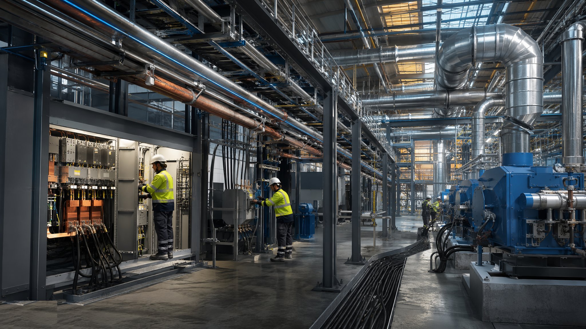
The arteries of the factory — compressed air ring mains, process water and steam, dust and fume extraction, HV/LV distribution for serious loads — built as production equipment, not building services with a bigger budget.
Last updated 2026-07-28 by the BuildPedia Editorial Team.
What is Industrial Services & Utilities?
Building services keep people comfortable; industrial services keep production alive, and they are engineered to a different standard of consequence. A factory's utility set typically includes a compressed air system (compressors, dryers, receivers and a ring main at 7–10 bar feeding drops to every machine), process and cooling water circuits, steam or thermal oil where the process cooks or cures, dust and fume extraction designed as local exhaust ventilation, gas supplies for process burners, and an electrical distribution system sized for motor and process loads that dwarf the lighting and small power. Each system is a production asset: when the air main pressure sags, the line slows; when the extraction fails, the process stops or the exposure limits get breached.
The distribution philosophy is what separates industrial MEP from commercial work. Utilities run in dedicated corridors — overhead pipe racks and cable ladder along the bays, utility trenches cast into the floor where the layout demands — so machines can be hooked up, moved and replaced without rebuilding the building. Busbar trunking with tap-off boxes replaces endless sub-mains for production power; compressed air runs in ring mains so any section can be isolated without starving the factory; extraction ductwork is balanced to design capture velocities at each hood, because HSE expectations for LEV (HSG258 territory) treat it as safety-critical plant with a legal Thorough Examination and Test regime. In the Gulf, the same plant runs harder: compressor intakes and cooling systems sized for 45 °C-plus ambient, condensate management in humid coastal air, and electrical derating that the data sheets only hint at.
The work is procured and phased with the production installation, not the base build: the utility corridors and primary plant (compressor rooms, HV switchrooms, pump sets) go in with the building, while the drops and final connections follow the machine vendor's certified utility schedule — which arrives late, changes twice, and must be chased with the same discipline as the foundation drawings. Standards are the industrial set: pressure systems under the Pressure Systems Safety Regulations with written schemes of examination for receivers and steam, electrical to BS 7671 with the industrial additions, ATEX-rated equipment wherever dust or vapour makes a zone, and Civil Defence-listed fire systems protecting it all in the UAE.
When and why is Industrial Services & Utilities used?
Industrial services are designed when the process defines its demands — air consumption per machine, extraction rates per hood, electrical loads per line — and installed so primary plant and corridors are ready before the first machine lands. Ring mains, racks and trenches are chosen because production layouts change: the factory that hard-wires every drop to a fixed layout is rebuilt at every line change. Central plant is sized with redundancy where stoppage costs justify it — N+1 compressors are cheap insurance against a line that dies for want of 7 bar. The mistakes that hurt are sizing from guesswork (undersized air mains that sag at shift peak, extraction that captures nothing at the hood that matters) and treating utility installation as second-fix trivia rather than the production-critical plant it is.
Types of Industrial Services & Utilities
Compressed air systems
Compressor houses with screw compressors (duty/standby), dryers, filtration and receivers feeding ring mains in aluminium, stainless or galvanised steel, with drops, isolation and condensate drains to each machine. The most-used and most-leaked utility in the building; pressure, dew point and leakage are managed as production metrics.
Process water, steam and thermal fluids
Water treatment, process and cooling circuits with pumps and heat exchangers; steam boilers and distribution with traps and condensate return where the process demands it. Pressure systems compliance, water chemistry and insulation are the disciplines; a steam main installed without gradient and trapping waterlogs itself into hammer and failure.
Dust and fume extraction (LEV)
Hoods, ductwork, fans and filtration capturing contaminants at source — welding fume, wood dust, process vapours — designed to capture velocities and balanced on commissioning, with Thorough Examination and Test as a legal duty thereafter. Where dusts or vapours are explosive, the system and its zone classification fall under the ATEX/DSEAR regime.
Industrial electrical distribution
HV intake and transformers, LV switchgear, busbar trunking with tap-offs along the bays, and motor control centres for production loads — with power factor correction, harmonics management and the metering the energy manager needs. Sized for diversity and growth; a switchroom with no spare ways is a factory with a ceiling on its future.
Industrial Services & Utilities: step by step
Step 1: Establish primary plant rooms and corridors
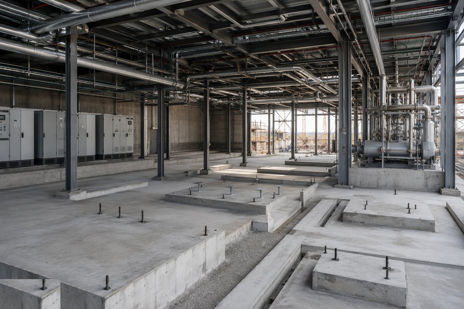
The primary plant goes in with the building programme: compressor house bases and plinths, HV switchroom fit-out with its transformer containment and cable trenches, pump and tank bases for the water systems, and the structural supports for the overhead racks that will carry everything. Utility corridors are set out as the frame completes — pipe rack and cable ladder runs along the bays at heights that clear cranes and forklifts, trench routes cast with the floor — because these corridors are the fixed infrastructure every later drop will hang from. Access for maintenance is designed in at this point or never: a receiver that cannot be inspected, or a rack run through a future mezzanine, is tomorrow's scaffold bill.
Step 2: Install the electrical backbone
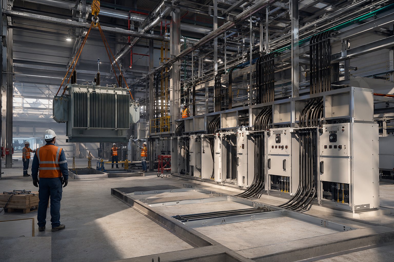
HV and LV switchgear is landed, levelled and torqued, transformers set with their oil containment and ventilation, and the distribution built outward: busbar risers and horizontal runs with tap-off positions per the layout, MCCs and motor supplies cabled on segregated containment, and the earthing and bonding system proven as an installation, not an assumption. Cables are tested before energisation — insulation resistance, continuity, polarity — and protection settings are engineered and injected, not left at factory defaults. Harmonic and power-factor studies from the design are verified as loads connect, because a factory full of VSDs on an uncorrected system cooks its own capacitors and upsets the DNO.
Step 3: Build the air, water and steam systems
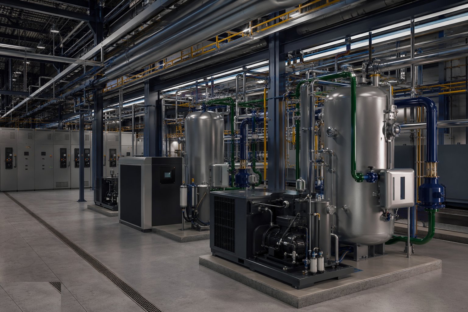
Compressors are set, aligned and piped to their dryers and receivers, with the ring main run in its specified material, falls to drain points, and isolation valves where the maintenance strategy needs them — every drop taken from the top of the main so condensate stays in the pipe, not the machine. Steam and condensate lines are erected with gradient, trapping and expansion taken by design, lagged after testing; water systems are flushed, dosed and balanced. Pressure testing precedes insulation everywhere, and the receivers and steam plant are registered into the written scheme of examination — the legal paperwork that keeps the Pressure Systems Regulations satisfied from day one.
Step 4: Install and balance the extraction
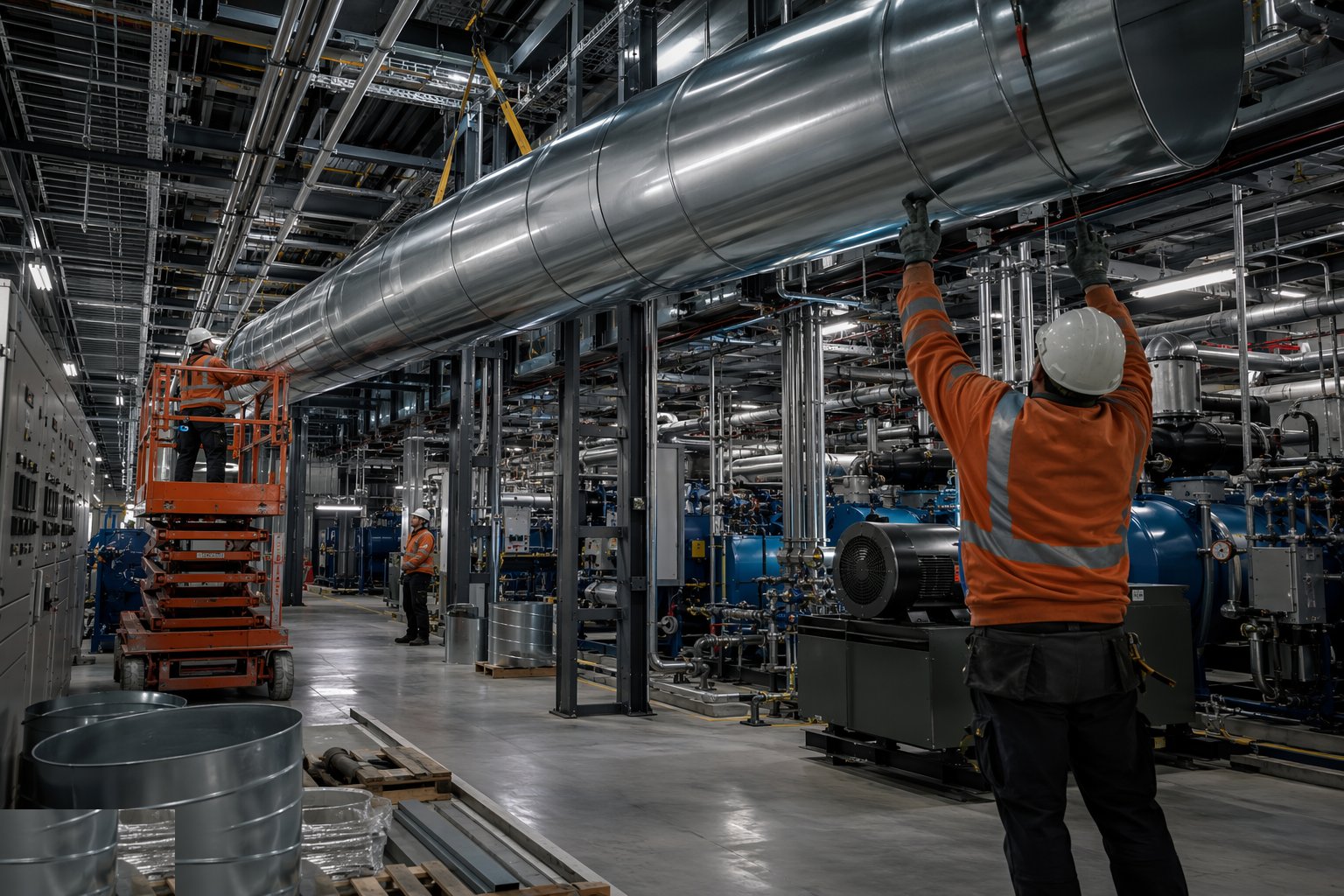
LEV ductwork runs from hood to fan to discharge with the fewest bends the building allows — every elbow costs capture velocity at the hood where it matters. Hoods are positioned per the design to the process sources, dampers fitted at branches for balancing, and fans set with their vibration mounts and discharge arrangements. Commissioning is measurement, not opinion: capture and transport velocities measured at hoods and in ducts, static pressures logged, dampers locked and marked once balanced, and the baseline recorded for the Thorough Examination regime that follows. ATEX-zoned systems get their rated fans, bonding and documentation as a package, certified, not implied.
Step 5: Connect machines and prove the utilities
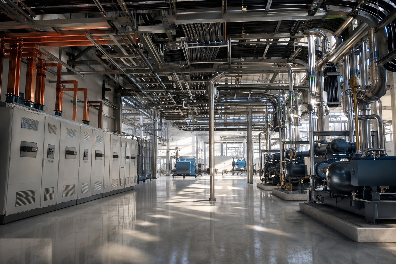
Final drops and connections follow the vendors' certified utility schedules: busbar tap-offs set, air drops with their isolation and regulation, water and drainage connections with backflow protection where the regs demand, gas supplies installed and tightness-tested by the appropriately registered engineers. Each utility is proven at the machine — pressure, flow, voltage under load — and the as-built schedules are updated, because the schedule that says 6 bar delivers 5.2 is a production complaint in waiting. The whole-system tests close the loop: air leakage rate measured on the shut-down test, extraction capture demonstrated at the sources, electrical load readings at the intake logged as the commissioning baseline.
Plant and equipment
- Screw compressors, dryers, receivers and filtration sets
- Busbar trunking, HV/LV switchgear, transformers and MCCs
- Pipe racks, cable ladder and containment systems; fusion and threading equipment
- Boilers, steam traps, pumps, heat exchangers and water treatment plant
- LEV fans, ductwork, hoods, dampers and filtration; velocity and pressure measurement kit
- Insulation resistance testers, protection injection test sets and power quality analysers
- Pressure test rigs and tightness-testing equipment for air, steam and gas
- MEWPs and access equipment for high-level rack and duct installation
Quality control checks
- Electrical test certificates per circuit and switchboard, with protection settings recorded as injected
- Pressure test records for air, steam and water systems before insulation; receiver registration into the written scheme
- LEV commissioning baseline: capture and duct velocities, static pressures and damper positions logged
- Air system dew point and leakage-rate test results at handover
- As-built utility schedules reconciled to the vendor requirements at every machine connection
- ATEX/DSEAR documentation for zoned systems; Civil Defence listings for fire-related systems in the UAE
Safety considerations
- Pressure systems: controlled testing, exclusion during pressurisation, and written-scheme discipline from first fill
- HV/LV electrical work under authorisation with lockout-tagout; live working only where justified and permitted
- Hot work near process hazards and ATEX zones: permits, gas testing and the zone documentation respected
- Work at height on racks and ductwork with collective protection as the default
- Stored energy in receivers and hydraulic/pneumatic circuits: depressurise and prove dead before breaking containment
- Noise and heat in compressor and plant rooms: hearing protection and Gulf heat-stress rules applied
Common defects
- Air drops taken from the bottom of the main, delivering condensate to every machine the system serves
- Extraction balanced by guesswork, capturing nothing at the source and failing its first Thorough Examination
- Busbar and switchroom installed with no spare capacity, capping the factory's expansion on day one
- Steam lines without gradient or trapping, waterlogging into hammer, erosion and joint failure
- Harmonics from VSD loads unmanaged, overheating transformers and tripping drives under production load
- Utility schedules never reconciled as-built, leaving machines starved of the pressure or flow their data plates demand
Best suited for
- New production facilities where utilities are sized to the process, not the floor area
- Factory expansions adding plant onto ring mains, busbar and spare corridor capacity
- LEV installation and upgrade where exposure control is a legal and production matter
- Gulf industrial plants where ambient conditions demand derated, hardened utility design
How long does Industrial Services & Utilities take?
Typical duration: Primary plant and corridors for a mid-sized factory install over 3–6 months alongside the base build; drops and final connections follow the production line installation, with utility proving typically completing 2–4 weeks ahead of cold commissioning..