Heavy Civils & Foundations
Equipment foundations, machine blocks, tank bases and piperack civils — the concrete that a process plant stands on, and the anchor bolts everything else lines up from.
Last updated 2026-07-28 by the BuildPedia Editorial Team.
What is Heavy Civils & Foundations?
Oil and gas civils are a different discipline from building foundations. The loads are industrial: a foundation may carry a static vessel that simply has to sit level for thirty years, or a reciprocating compressor that will try to shake its own block apart every second of its working life. The first job on any process unit is sorting foundations into these two families. Static equipment foundations — vessels, columns, heat exchangers, drums — are essentially robust plinths designed for load, settlement and spill containment. Machine foundations for compressors, turbines and large pumps are dynamic structures in their own right, designed so the machine and its concrete block behave as one tuned mass: block proportions, embedment and soil stiffness all feed a dynamic analysis, and the rule-of-thumb mass ratios used at concept stage get checked properly before a cube of concrete is poured.
The detail that rules the whole stage is the anchor bolts. Every vessel skirt, every compressor baseplate and every steel column lands on cast-in holding-down bolts, and the steel or equipment fabricated months earlier in another country will only fit if the bolts are where the drawing says they are. Bolts are set in templates or frames, surveyed before and after the pour, and protected until handover; position and level tolerances are tight — commonly only a few millimetres on position and a millimetre or so on level across a group, per the project specification — and a bolt group poured wrong can mean cutting out a machine foundation, not just an awkward phone call. Bolt sleeves and adjustable arrangements buy some forgiveness; straight cast-in bolts buy none.
Tank foundations are the other heavyweight. Atmospheric storage tanks to API 650 sit on prepared ground rather than piled rafts in most ground conditions: a compacted crushed-stone ring beam or concrete ring wall under the tank shell, with a crowned, compacted fill and a bituminous sand pad under the bottom plates to protect against underside corrosion and to level the plates. In the UAE the ground adds its own demands — sabkha and saline groundwater mean sulphate-resisting binders, increased cover and serious attention to hot-weather concreting on the big machine blocks, which pour as mass concrete with thermal control. On an ADNOC or other operator site, all of it runs under the operator's permit-to-work system and inspection regime, and the civils ITP is agreed before the first excavation.
When and why is Heavy Civils & Foundations used?
Heavy civils come immediately after the survey and ground investigation because everything in a process plant — the steel, the vessels, the compressors, the piping — is set out from, landed on or bolted to these foundations, and long-lead equipment is already being fabricated to the anchor-bolt drawings. It matters because errors here are the hardest to recover on the whole job: a machine foundation with a wrong bolt group, a tank pad with differential settlement, or a block with a thermal crack through the anchor zone does not get snagged and painted over — it gets demolished or it gets a compromise the plant lives with for decades. The civils stage also sets the survey control that the steel and piping erectors will inherit, so sloppiness propagates. There is no domestic version of a machine foundation — the closest a house gets is the plinth under a standby generator or the base of a heating-oil tank, where the same instincts apply: level, drained, founded on something proven, and never cast over soft fill.
Types of Heavy Civils & Foundations
Machine (dynamic) foundations
Blocks and tables for rotating and reciprocating machinery — compressors, turbines, large pumps and blowers. Designed with a dynamic analysis so the machine-foundation-soil system's response stays within the vendor's vibration limits, they are typically large, heavily reinforced mass pours with precisely templated anchor bolts, poured with thermal control and left to gain strength before the machine is set.
Static equipment foundations and pedestals
Plinths and pedestals for vessels, columns, drums, exchangers and filters, designed for dead load, wind, seismic where applicable, and bund or spill containment requirements. The critical features are the anchor-bolt groups and the bearing level — vertical vessels want flat, level foundations with the bolts on the right pitch circle diameter, because the skirt is already made.
Tank foundations
Foundations for atmospheric storage tanks to API 650: a crushed-stone or concrete ring beam under the shell carrying the shell load, crowned compacted fill within it, and a bituminous sand layer under the bottom plates. Settlement criteria — total and, worse, differential around the circumference — govern the ground treatment beneath, and leak detection and edge protection details are set at this stage.
Piperack and miscellaneous civils
The linear civils that stitch the plant together: piperack column foundations (or ground-bearing sleeper beams for low-level pipeways), cable-trench routes with covers, blast-rated or fire-rated buildings for substations and analysers, and the oily-water and process drainage network buried beneath everything. None of it is glamorous and all of it is on somebody's critical path.
Heavy Civils & Foundations: step by step
Step 1: Verify ground and set out from primary control
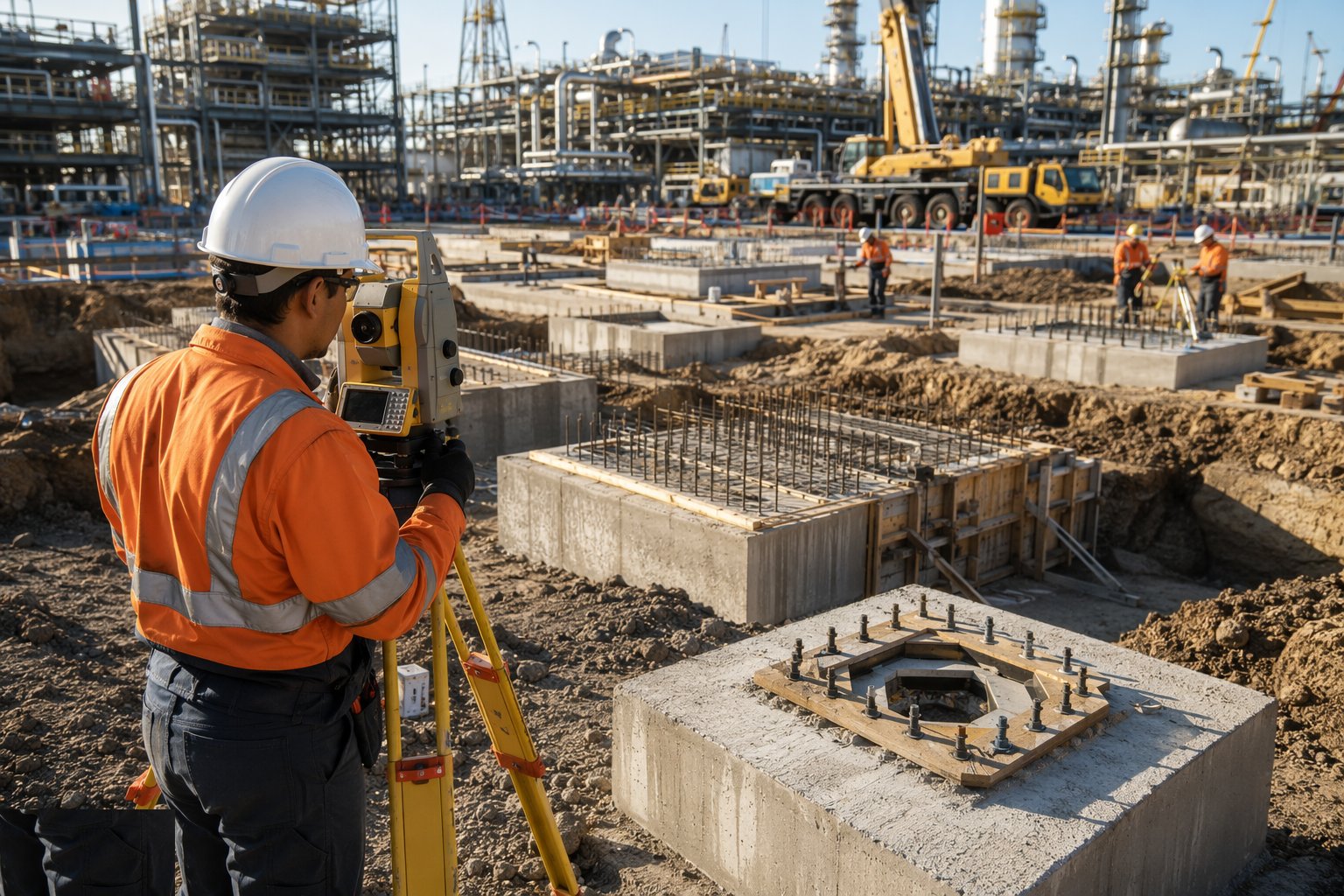
Confirm the formation conditions against the ground investigation at each foundation location — the GI is a sample, not a guarantee, and a machine foundation position that hits made ground or a soft pocket gets resolved now, not after the pour. Set out every foundation, bolt group and benchmark from the site's primary control network, and hold the setting-out records as quality records: the steel and equipment erectors will inherit them wholesale. On operator sites, the excavation itself needs the permit to dig and service clearances like any other.
Step 2: Excavate and prepare the formation
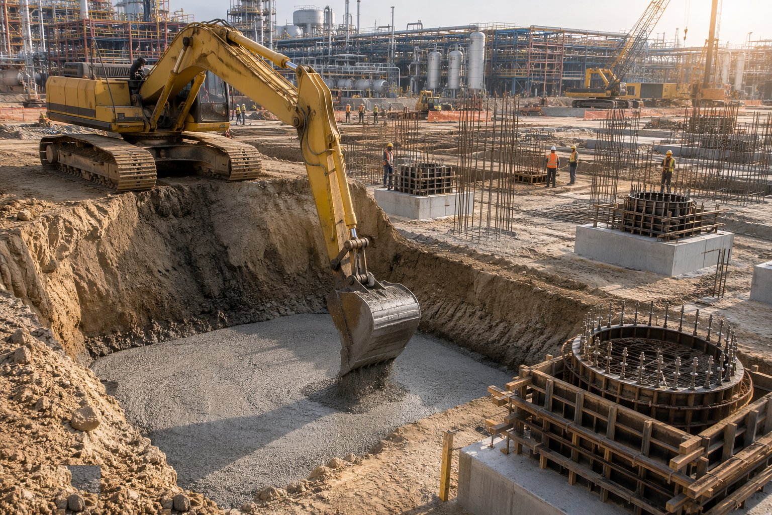
Excavate to formation with support or battering as the ground demands, keeping the base undisturbed and dry — sump pump carefully in sands to avoid boiling the formation, and use wellpoints or deep wells where drawdown is significant. Blind the formation promptly to seal it, and get the foundation inspection signed off on the ITP before anything is placed on it. In saline Gulf ground this is where the durability measures start: the formation chemistry confirmed, the membrane or protection specified in the design laid, and no shortcuts.
Step 3: Fix reinforcement, formwork and embedments
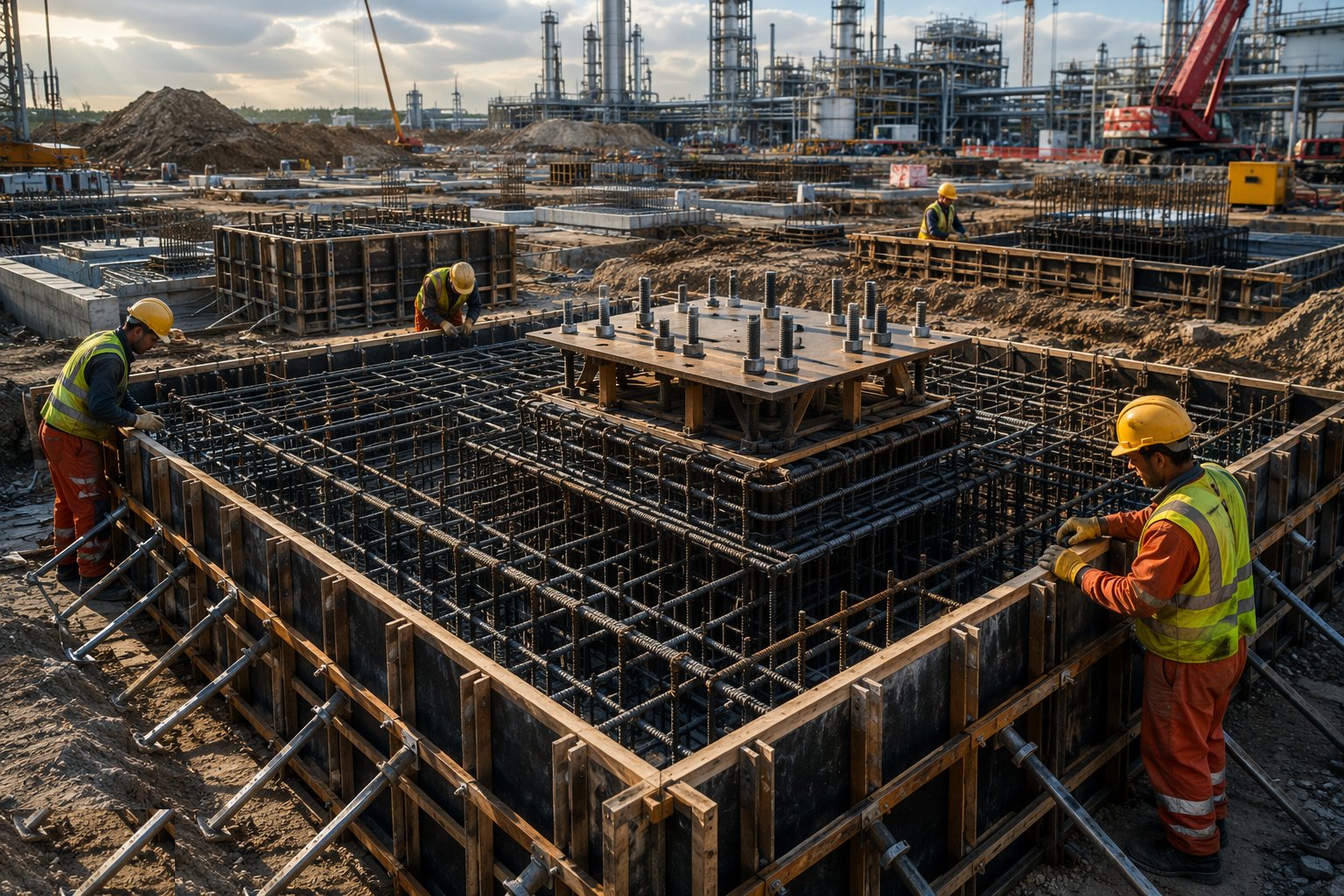
Fix the reinforcement to the drawings with the specified cover — higher covers and sulphate-resisting mixes are the norm in chloride and sulphate ground — and form the box. This is the stage where the embedments go in: anchor bolts in rigid templates or frames tied back to the shutter, bolt sleeves, earthing bosses, cable ducts, embedded plates for later steel. Every embedded item is checked against the latest revision of the vendor or steel drawing, because these drawings have a habit of revising while the rebar is being fixed.
Step 4: Survey and secure the anchor bolts
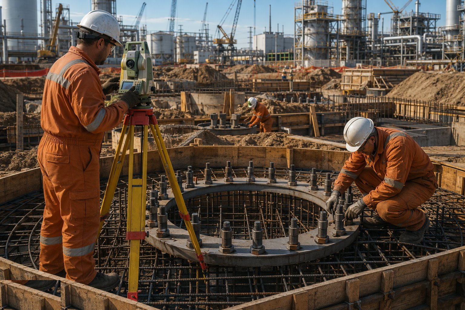
Survey the bolt groups in the formwork before the pour — position, level, verticality and projection — and have it witnessed as a hold point. Fix the templates so they cannot float or kick during concreting; a vibrator against a bolt cage will move it. Where the specification allows adjustable arrangements, still set them to the nominal position: adjustment is for millimetres, not centimetres. Record the as-set survey so the post-pour survey can prove nothing moved.
Step 5: Pour with thermal and hot-weather control
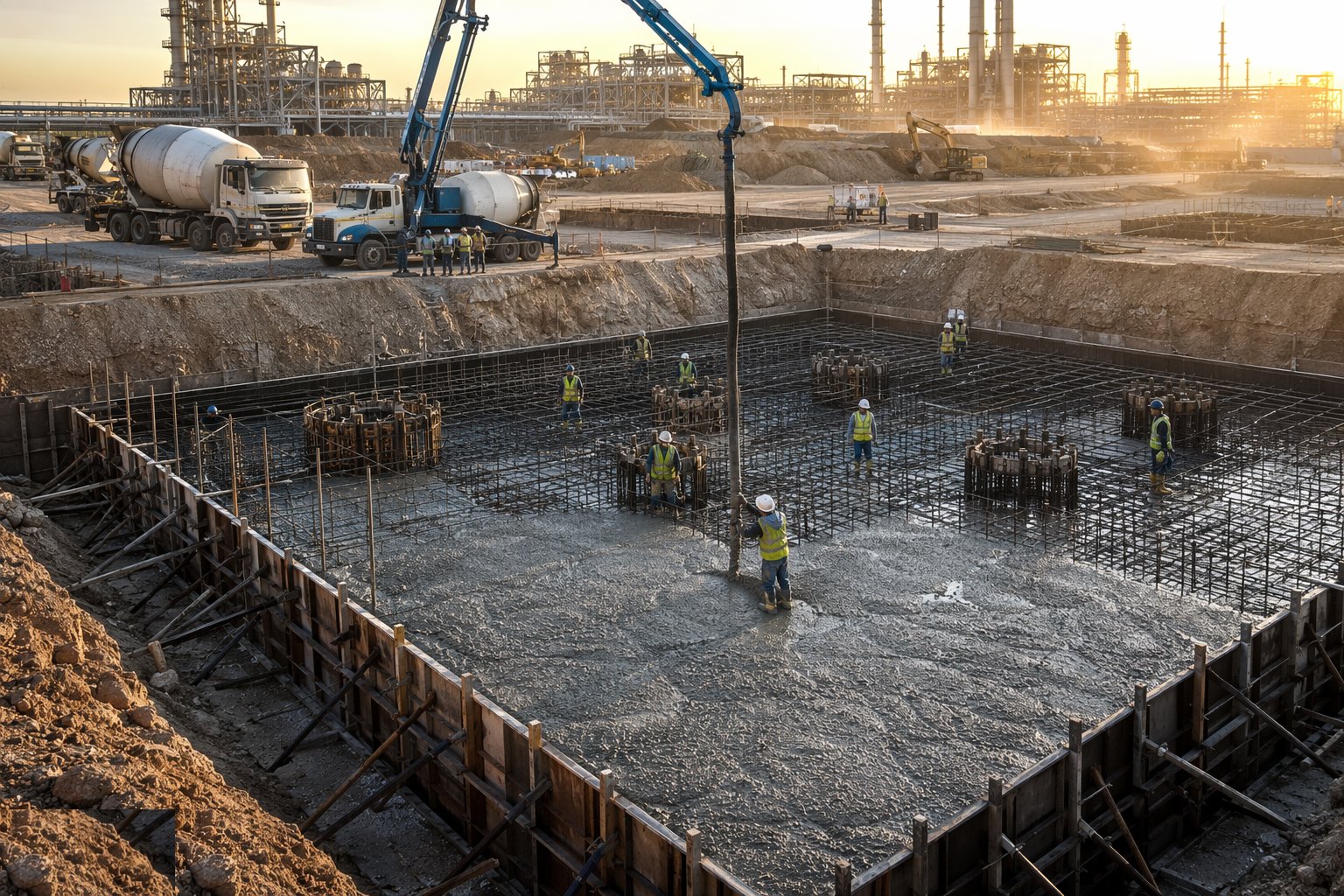
Machine blocks pour as mass concrete: agree the mix (low-heat or GGBS-rich binders are common), the pour temperature limits, the thermal monitoring and the curing regime before the first truck. In the Emirates, apply the hot-weather rules properly — chilled mix water or ice, shaded materials, night or early-morning pours in summer, no retempering with water — and place continuously to avoid cold joints through the anchor zone. Cube or cylinder samples are taken per the specification and tracked to the pour records.
Step 6: Cure, strike, survey and backfill
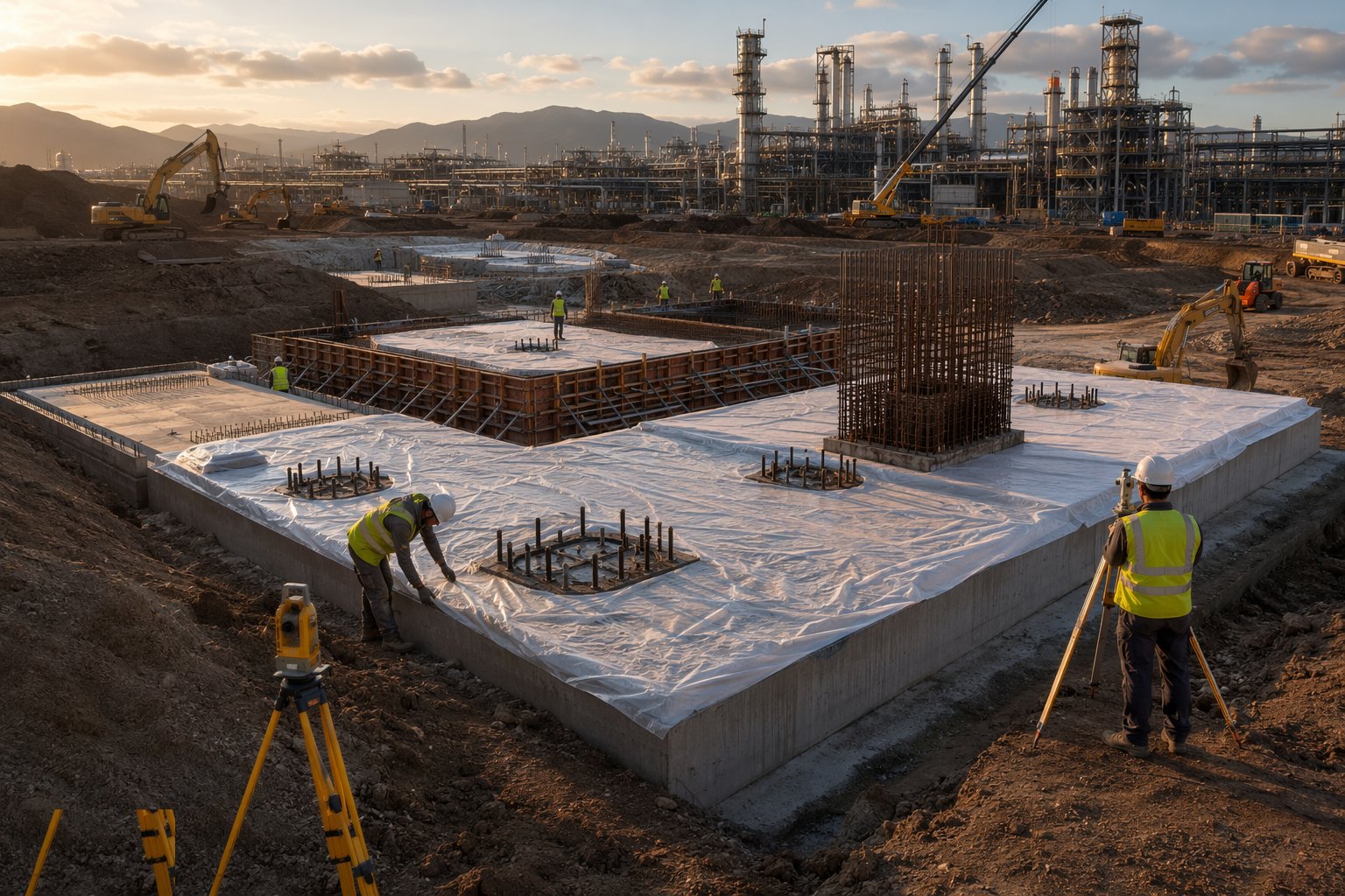
Cure for the specified period — water curing, curing membranes or insulated curing on mass pours, with the thermal monitoring running until the gradient is within limits. Strike the formwork only when strength allows, then re-survey the bolt groups and foundation levels as the as-built record; any movement beyond tolerance triggers an engineering resolution, not a quiet grinder. Backfill in engineered layers with compaction testing, and reinstate waterproofing or protection before covering.
Step 7: Grout sleeves and hand over to erection
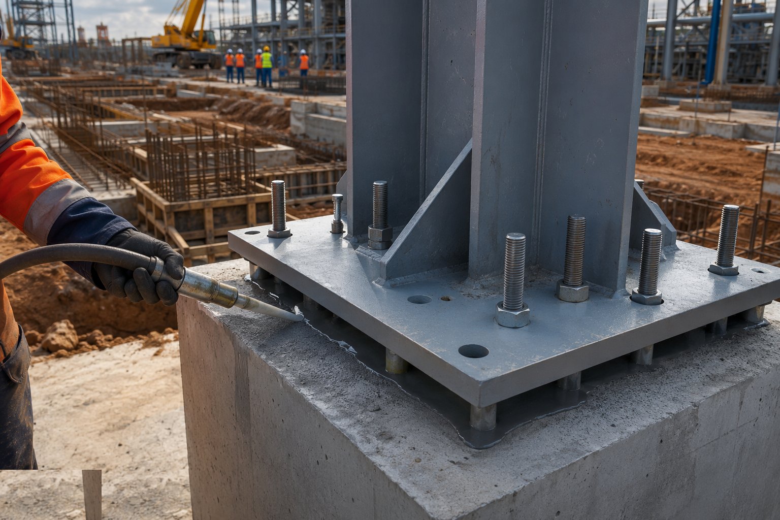
Where bolt sleeves or pockets are used, grout them with the specified non-shrink grout once the equipment or steel is landed and aligned — this step belongs partly to the erection stage, but the civils contractor owns the grout specification and the surface preparation. Complete the foundation release documentation: as-built surveys, pour records, cube results, bolt-group certificates, all indexed against the foundation number. No foundation is handed to the mechanical erector without its release note — that is how bolt errors get caught at the gate instead of at the crane hook.
Plant and equipment
- 360° excavators, dozers and compaction plant for excavation and backfill
- Wellpoint or deep-well dewatering sets where groundwater controls
- Formwork systems, bolt templates and setting frames
- Concrete pumps, truck mixers and poker vibrators
- Ice plants or chilled-water systems for hot-weather concreting (Gulf)
- Thermal monitoring loggers and thermocouples for mass pours
- Total stations and precision levels for bolt-group surveys
- Non-shrink grout, mixing paddles and grout pumps
Quality control checks
- Foundation locations set out and checked from primary control; records filed
- Formation inspection signed off on the ITP before blinding
- Anchor-bolt survey before and after every pour, witnessed as a hold point
- Concrete temperature, thermal gradient and cube/cylinder results tracked per pour
- Sulphate-resisting binder and cover verified in saline ground
- Bolt protection maintained between pour and handover — capped and greased
- Tank ring-beam level checked around the full circumference; settlement points installed
- Foundation release certificates issued before steel or equipment erection starts
Safety considerations
- Excavation support, battering or benching; permit to dig with service clearances
- Permit-to-work compliance on operator sites — gate pass, induction, task permits
- Concrete burns and cement dermatitis controls for placing and finishing crews
- Vibration white-finger and noise controls on pokers and compaction plant
- Heat-stress management and midday-break compliance for Gulf summer pours
- H2S awareness and gas testing where excavating on live or brownfield plant areas
- Confined-space controls in deep pump pits and drainage structures
Common defects
- Anchor bolts out of position or projection — machine baseplate will not land
- Bolt templates moved during the pour; nobody re-surveyed until striking
- Thermal cracking through a mass block poured hot without monitoring
- Cold joint through the anchor zone from an interrupted pour
- Tank pad with differential settlement — shell distortion shows at hydrotest
- Bituminous sand pad omitted or contaminated — underside corrosion of tank bottom
- Wrong revision of vendor bolt drawing used — foundation cast to a superseded drawing
- Cover or durability class short-changed in saline ground — early reinforcement corrosion
Best suited for
- Equipment foundations, machine blocks and tank bases
- Piperack and technological-structure civils
- Anchor-bolt grids that precision equipment aligns from
- Heavy pours on congested industrial sites
How long does Heavy Civils & Foundations take?
Typical duration: Typically 4–9 months for the civils of a process unit or tank farm area, with machine foundations and tanks on the critical path and long-lead equipment bolt drawings needed early; brownfield work runs slower under permit constraints..