Piping & E&I Installation
Pressure piping fabricated as spools and welded to qualified procedures, plus the cable, tray and instrument installation that makes the plant controllable — the longest bulk-installation phase on the job.
Last updated 2026-07-28 by the BuildPedia Editorial Team.
What is Piping & E&I Installation?
Piping is where an oil and gas project spends most of its site hours. Process piping to ASME B31.3 (or the project's specified code) is fabricated as spools — shop-made pipe assemblies with flanges and fittings — because shop welding under cover with positioners beats field welding on a rack in every respect: quality, productivity and weather independence. Spools arrive at site with weld maps and material traceability, and the site work is erection: setting spools on their supports, making the final field welds, and managing the weld-and-inspect loop. Welding is done to qualified procedures (WPS/PQR) by welders qualified to ASME Section IX in US-code practice or EN ISO 9606 in European practice, and the NDT regime — radiography, ultrasonic, dye penetrant, magnetic particle, in proportions set by the piping class — decides how much of it gets examined. Every weld is logged against a welder, a procedure and a test result.
Electrical and instrumentation runs in parallel and ends up on the same critical path. The electrical scope is the heavy-current skeleton: HV/MV switchgear and transformers (often by a specialist package contractor), cable tray and ladder rack along the piperacks and trenches, cable pulling in the thousands of drum lengths, glanding and termination at motors, lighting and small power. The instrument scope is finer: field instruments on their stands and impulse lines, junction boxes, instrument cable and screen segregation, and the analyser and control system installation. Everything terminates in the control system, and the proving activity — loop checks from field device through marshalling to the DCS faceplate — is where installation quality meets commissioning.
Hazardous-area discipline overlays all of it. Areas where flammable gas or vapour may be present are classified into zones — Zone 0, 1 and 2 for gases and vapours under the ATEX/IECEx framework (Zones 20–22 for dusts) — implemented in the UK through DSEAR, and every piece of electrical and instrument equipment installed in a classified area must carry the correct Ex certification (Ex d flameproof, Ex e increased safety, Ex i intrinsically safe and so on), installed exactly per its certificate: the right glands, the right stopping plugs, the right torque. In the UAE the same framework applies through IECEx, with operator specifications — ADNOC's among them — adding their own requirements, and sour service (H2S) plants adding materials compliance to NACE MR0175/ISO 15156 on top of the electrical rules. Permit-to-work culture governs every task, and material traceability with positive material identification (PMI) on alloy piping closes the loop.
When and why is Piping & E&I Installation used?
Piping and E&I follow steel and equipment setting because the spools are fabricated to the as-set geometry — nozzle positions, rack elevations and machine locations — and the cables route on the racks and through the trenches the earlier stages built. It matters because this is the longest and most rework-sensitive phase: weld repairs burn programme and NDT capacity, cable and gland mistakes in classified areas fail inspection wholesale, and every outstanding loop check at the end of the job lands directly on the commissioning critical path. The documentation built here — weld logs, NDT reports, test records, Ex inspection records — is also the bulk of the handover dossier and the legal demonstration that the plant is fit for hydrocarbons. The domestic echo is the boiler room or plant room: press-fit copper and plastic instead of welded spools, but the same iron rules — materials identified, every concealed joint pressure-tested before boxing-in, and certificates filed, because buried leaks do not respect property values either.
Types of Piping & E&I Installation
Process and utility pressure piping
Carbon, alloy and stainless piping to ASME B31.3 or the project code, fabricated as spools and erected onto supports with a controlled field-weld and NDT programme. Covers process lines, utility headers, steam, instrument air and relief systems — the piping class for each line sets the material, the welder qualification, the NDT percentage and the test pressure.
Electrical power installation
HV/MV switchgear, transformers, motors, cable tray and ladder rack, power cable pulling, glanding and termination, plus lighting, small power, earthing and lightning protection. In classified areas all equipment and glands carry the matching Ex certification, and installations are inspected against the certification drawings — not just wired and energised.
Instrumentation and control
Transmitters, analysers, control valves, junction boxes and instrument cabling with screened segregation from power, impulse lines and air sets, marshalling into the DCS or PLC, and the loop-check regime that proves every signal end to end. Smart instruments are configured and ranged during installation, and every loop gets a signed check sheet before pre-commissioning.
Specialist packages
Vendor-scoped systems installed alongside the bulk work: fire and gas detection, deluge and firewater, analysers and sampling systems, telecoms and CCTV, cathodic protection on buried lines and tanks. They arrive with their own vendor representatives and commissioning procedures, but their cable routes and tie-ins must be coordinated with the bulk installation to the day.
Piping & E&I Installation: step by step
Step 1: Control materials and traceability
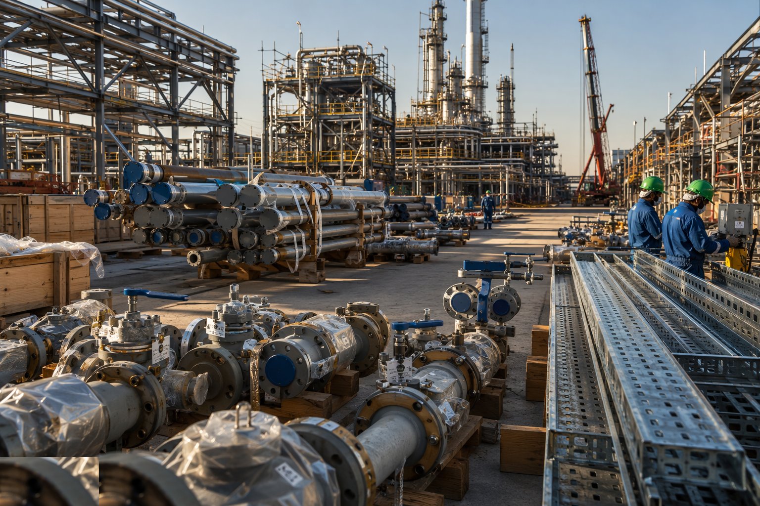
Receive pipe, fittings, flanges and valves against the piping classes: check certificates (3.1 mill certs where specified), marking and condition, and run PMI on alloy and stainless items to prove the material is what the certificate says — a single carbon-steel elbow in an alloy line is a catastrophic service failure waiting to happen. Segregate materials by class in the stores, preserve machined faces and valve internals, and keep the traceability records live: every spool drawing will reference heat numbers from this point on.
Step 2: Fabricate and test pipe spools
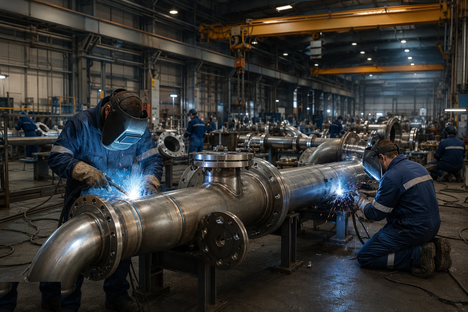
Fabricate spools in the shop to the isometrics: cut, bevel, fit-up with proper alignment and purge arrangements for stainless and alloys, and weld to the qualified WPS by welders holding valid qualifications for the process and position. Log every weld against welder, procedure and spool, and run the NDT regime — the weld map fills in as radiographs and reports return. Repairs go through the same loop with documented repair welds, and spools are cleaned, capped and painted before dispatch to site.
Step 3: Erect spools and make field welds
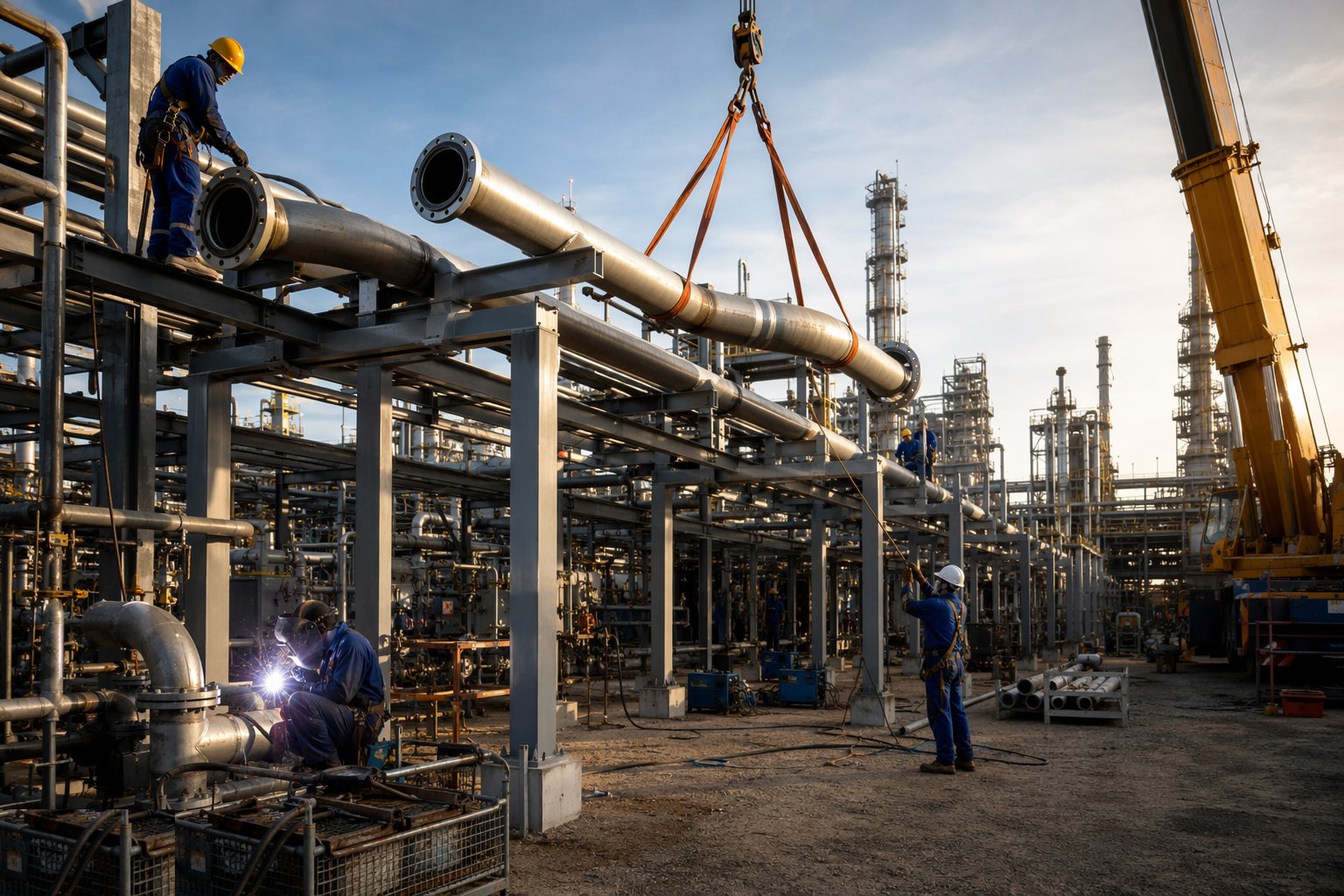
Set spools onto their supports in the surveyed geometry — spring supports and special items installed per the drawing, with travel stops and settings recorded — and make the field joints: flanged joints torqued with controlled procedures and the correct gaskets, field welds to the same qualification and NDT regime as the shop. Protect open ends religiously; a spool full of site debris is a blocked control valve in six months. Fit-up quality at field welds is the site's reputation — the NDT return rate proves it one way or the other.
Step 4: Install cable containment and pull cables
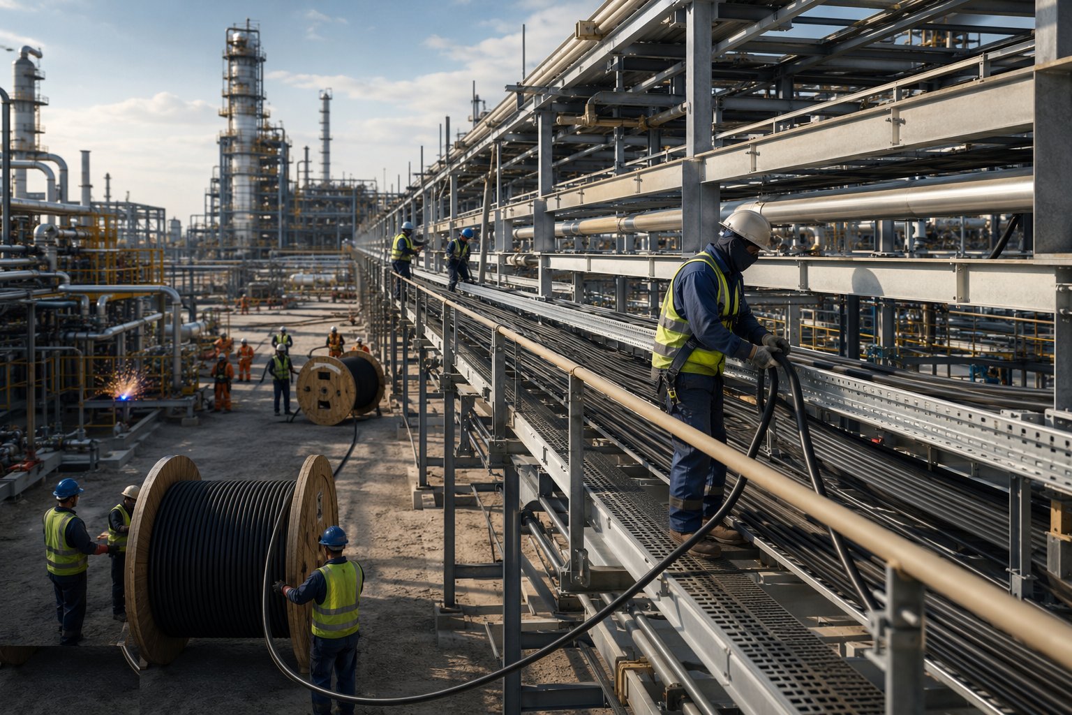
Erect tray and ladder rack on the racks and in the trenches with the specified separations — HV from LV from instrument, with covers where required — then pull cables from a drum schedule that minimises joints and wastage. Respect minimum bend radii, support and cleat to the design (single-core cleating is a short-circuit withstand matter, not tidiness), and identify every cable both ends as it is pulled. Cable pulling is logistics: drum management, pulling tensions and route completion decide the rate.
Step 5: Gland, terminate and test
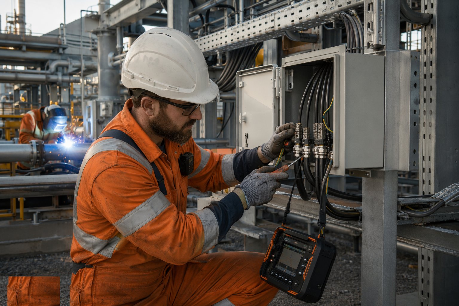
Gland and terminate to the certified arrangements: the correct Ex gland for the cable construction and the equipment entry, shrouds, earth tags and stopping plugs where certificates demand them. Torque and dress terminations, megger and continuity-test every cable before energisation, and record the results against the cable schedule. In classified areas, the Ex inspection regime (graded detailed/close/visual per the standard) signs off installations before they are accepted — gland mistakes found here are cheap; found at energisation they are not.
Step 6: Install and hook up instruments
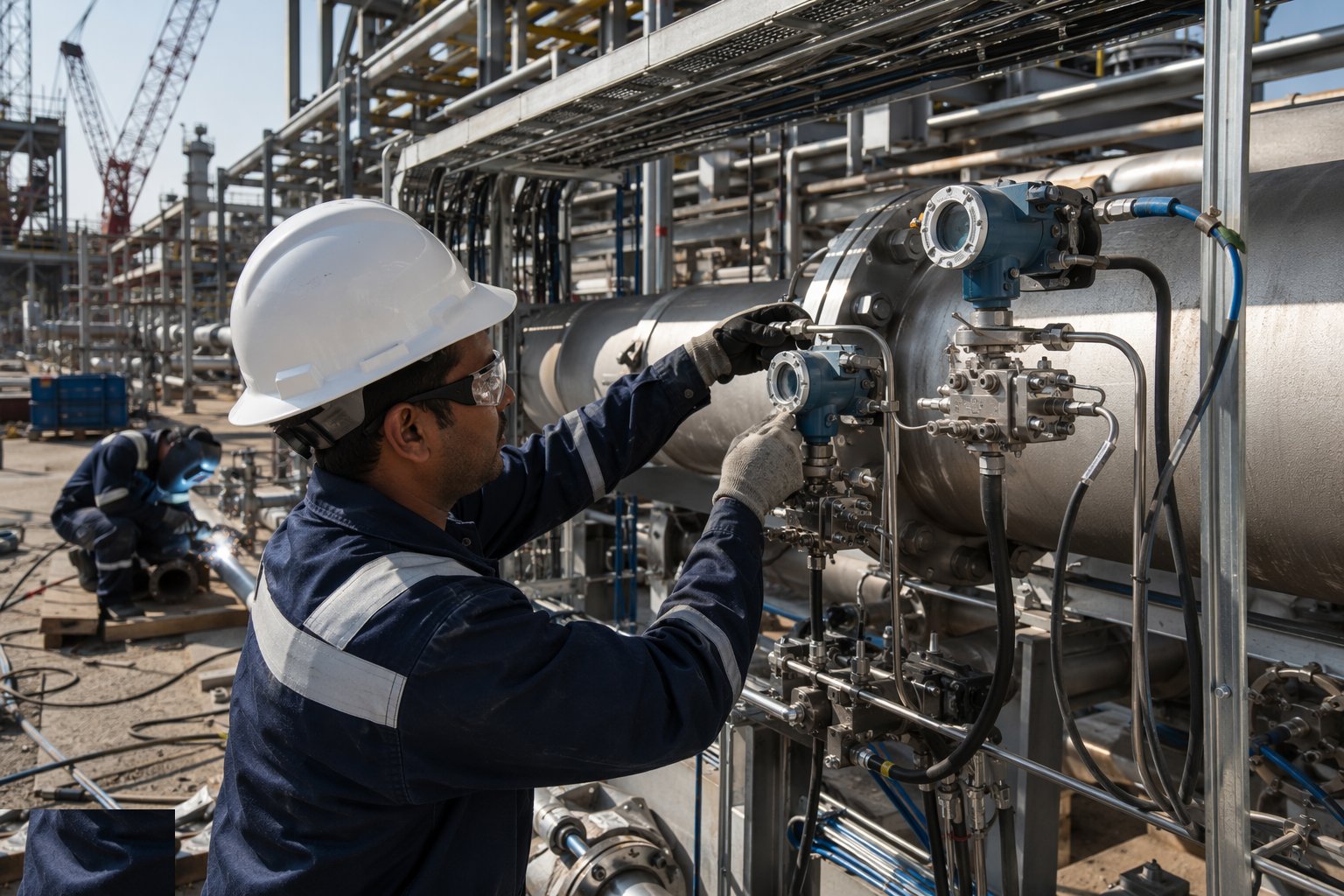
Mount field instruments at the accessible, readable positions the detail drawings show — impulse lines sloped correctly with no pockets, air sets and manifolds orientated so they can be maintained — and run instrument cabling with screen earthing at the marshalling end per the design. Configure and range smart instruments, witness vendor installations on analysers and control valves, and record every installed device against its data sheet and calibration certificate.
Step 7: Run loop checks and close the punch
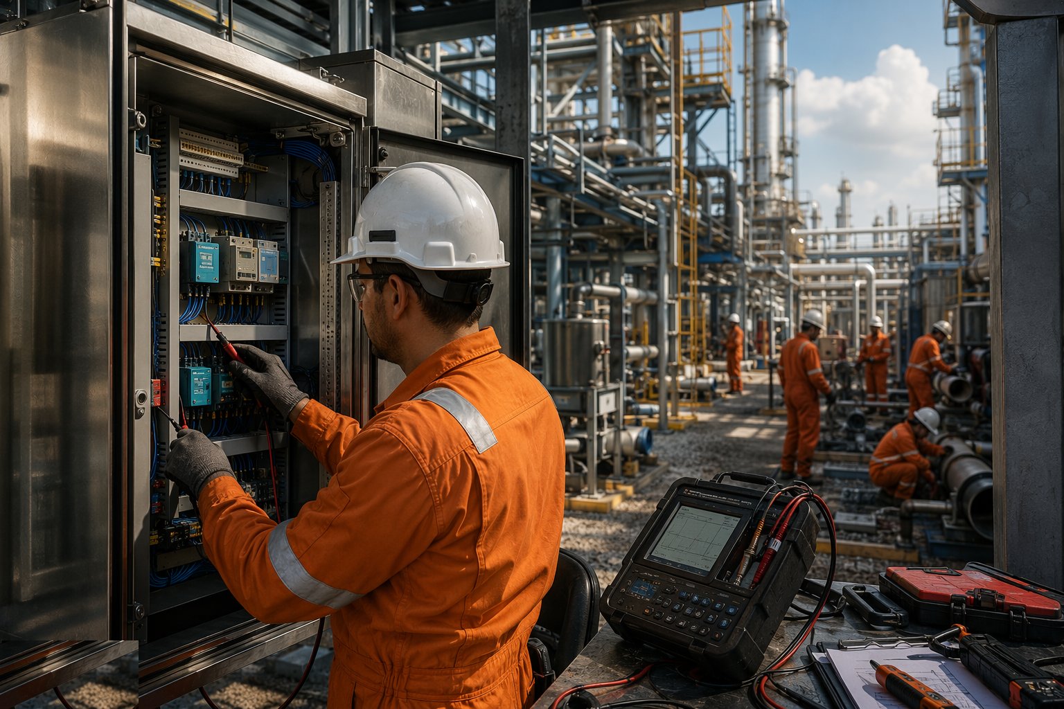
Prove every loop from sensor to screen: inject or simulate at the field device, confirm the signal through the marshalling to the DCS faceplate, exercise outputs to valves and watch them stroke, and sign the loop check sheets. Loop checks surface the accumulated sins of installation — crossed pairs, earthed screens at both ends, mis-ranged transmitters — and each one found is a punch item against a system boundary. The punch list, managed by system, is the handover currency to pre-commissioning: no system transfers with open Category A items.
Plant and equipment
- Pipe spool fabrication shop: saws, bevellers, positioners and purge equipment
- Welding sets (TIG/MMA/flux-cored), ovens and electrode quivers
- NDT contractors: radiography, UT, dye-penetrant and MPI equipment
- PMI analysers (XRF) for alloy verification
- Cable drum jacks, rollers, pulling winches and tension monitors
- Torque wrenches, tensioners and flange-management equipment
- Megger, continuity and loop-check test sets; HART communicators
- Mobile cranes and MEWPs for rack installation
Quality control checks
- Material certificates and PMI results traceable to spool and line numbers
- WPS/PQR and welder qualification records current for every weld
- Weld logs and NDT reports closed out; repair rates monitored by welder
- Flange management: torque records and gasket traceability per joint
- Cable test records (megger/continuity) against the cable schedule
- Ex inspection records for every classified-area installation
- Instrument data sheets, calibration certificates and configuration records filed
- Loop check sheets signed; punch list managed by system
Safety considerations
- Permit-to-work for every task; gas testing before hot work anywhere on site
- Hazardous-area discipline: no uncertified equipment or tools in classified zones
- Radiography exclusion zones and notification for night-time RT
- Arc-eye, fume and hot-work controls in welding bays and on racks
- Working at height on racks and tray runs; dropped-object prevention
- H2S awareness, personal monitors and escape respirators on sour-service plants
- Cable pulling: drum stand stability, pulling-tension limits, manual handling
- Heat stress on racks and in trenches during Gulf summers
Common defects
- Wrong material installed in a line class — PMI skipped at receipt
- Welder working outside their qualification range — NDT rejects and re-qualification
- Open pipe ends left uncapped — debris found at flushing or, worse, in a valve
- Incorrect Ex glands fitted — fails the detailed inspection wholesale
- Instrument screens earthed at both ends — noise on the loops at commissioning
- Impulse lines with pockets or wrong slope — false readings in service
- Cable cleating omitted on single-core runs — short-circuit withstand compromised
- Loop checks left to the end — commissioning critical path collapses under the backlog
Best suited for
- Pressure piping fabricated as spools and welded to qualified procedures
- Cable, tray and instrument installation across the plant
- The longest bulk-installation phase of the project
- Systems completion organised test pack by test pack
How long does Piping & E&I Installation take?
Typical duration: Typically 8–18 months for the piping and E&I bulk installation on a process unit — the longest phase on the programme, overlapping heavily with pre-commissioning at the system boundaries as they complete..