Structural Steel & Equipment Setting
Piperack steel, technological structures and the heavy lifts that land vessels, columns and compressors onto the civils — planned to BS 7121 and surveyed to the millimetre.
Last updated 2026-07-28 by the BuildPedia Editorial Team.
What is Structural Steel & Equipment Setting?
Once the foundations are released, the plant starts to look like a plant. Structural steel on an oil and gas facility is not a building frame: it is piperacks carrying process lines between units, technological structures supporting vessels and air coolers at height, equipment platforms, stairways and access steel, and the substation and blast-resistant buildings. Fabrication is done off site — to BS EN 1090 execution classes in the UK market or the operator's project specification in the Gulf — and the site work is assembly: members and pre-assembled rack sections arrive blasted, coated or galvanised, and the erector's job is to bolt them up plumb, level and on the anchor bolts the civils stage left behind.
The defining activity of this stage is the heavy lift. Columns, reactors, drums and compressors arrive as single items weighing from tens to hundreds of tonnes, and each one lands on a foundation in a pick that was planned weeks before the crane mobilised. In the UK, lifting operations are planned to BS 7121, the code of practice for the safe use of cranes: an Appointed Person plans every lift, categorises it (routine to complex), produces the lift plan with ground-bearing checks, crane configuration and rigging studies, and a crane supervisor runs the lift on the day under LOLER duties. Tandem lifts, lifts over live plant and lifts at high utilisation are treated as complex lifts with commensurate scrutiny. In the UAE the same planning culture applies under the operator's standards — ADNOC and the other operators run their own lifting requirements on top of international good practice, with third-party certified cranes and riggers and permit-controlled lift windows.
Setting equipment is a survey discipline as much as a rigging one. A vertical vessel is landed on its bolts, levelled on shim packs, checked for plumbness at two elevations with the instrument, and only then grouted; a compressor is set, levelled and aligned to its driver on the common skid or sole plates before final grouting. Every lift and every setting feeds the alignment records that the piping stage will rely on — a vessel nozzle that is 20 degrees out of orientation or a rack beam 15 mm low is a piping problem by next month, discovered at the worst possible time.
When and why is Structural Steel & Equipment Setting used?
Steel and equipment setting follows foundation release because it literally stands on the civils work — the bolt surveys, grout and release certificates from the previous stage are its starting documents. It matters because this stage fixes the geometry of the whole plant: pipe-rack elevation errors become pipe-support problems, vessel orientation errors become nozzle re-work, and a compressor set out of level becomes a reliability problem for the plant's whole life. It is also the highest-consequence stage for safety: a dropped load or a crane failure during a heavy lift is a fatal-event scenario, which is why lift planning to BS 7121 and the operator's lifting standards is non-negotiable and why weather windows, ground conditions and exclusion zones are policed so hard. Nothing at house scale resembles a two-hundred-tonne column lift; the nearest echo is setting a steel mezzanine beam or a packaged plant skid with a telehandler, where a written lift plan, checked ground and an exclusion zone still separate a routine pick from an accident report.
Types of Structural Steel & Equipment Setting
Piperack and technological structures
Multi-level steel racks carrying process and utility lines between units, plus the structures supporting air coolers, vessels and flare systems. Erected as individual members or pre-assembled bays, bolted up on cast-in anchor bolts, plumbed and levelled on shims and grouted — the alignment survey at completion is the document the piping designers and stress engineers build from.
Vertical vessels and columns
Towers, drums, absorbers and reactors lifted upright — sometimes with internals, trays and insulation already fitted to minimise work at height — and landed on skirt bolt circles. These are usually the heaviest picks on the job: crawler cranes or heavy all-terrains, lift studies with tailing plans, and strict wind limits because a tall vessel is a sail.
Horizontal equipment and rotating machines
Exchangers, horizontal drums, pumps and compressor packages set onto sleepers, plinths or sole plates. The lifts are usually routine by weight but the setting is precision work: level, line and elevation to tight tolerances, then alignment between driver and driven machine before grouting, because the piping connections and the machine's reliability both depend on it.
Modular and pre-assembled units
Pipe-rack modules, pre-assembled units (PAUs) and skidded packages fabricated and dressed off site — overwhelmingly the Gulf pattern on large ADNOC and LNG projects, where yard fabrication quality and reduced site hours at height outweigh the transport and lift logistics. Site work is setting modules onto prepared foundations and making the interconnections.
Structural Steel & Equipment Setting: step by step
Step 1: Receive, inspect and lay out the steel and equipment
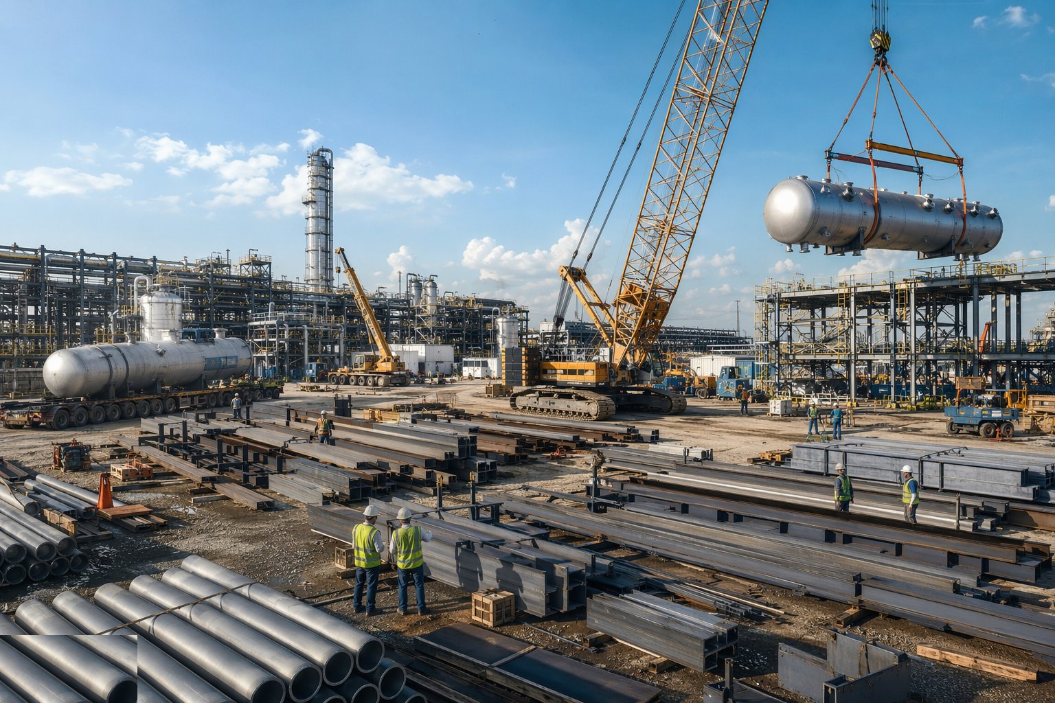
Check deliveries against the packing lists and drawings: member marks, coating condition, bolt sets with their certificates, and equipment for transport damage — a vessel nozzle bent in transit is found at laydown, not at the hook. Lay down steel and equipment in erection sequence with proper dunnage and drainage, keeping high-value instruments and machined faces protected. On operator sites, preservation starts now: flange faces capped, rotating equipment shafts barred over per the vendor schedule, desiccant and nitrogen blankets maintained where specified.
Step 2: Survey foundations and prepare bearing surfaces
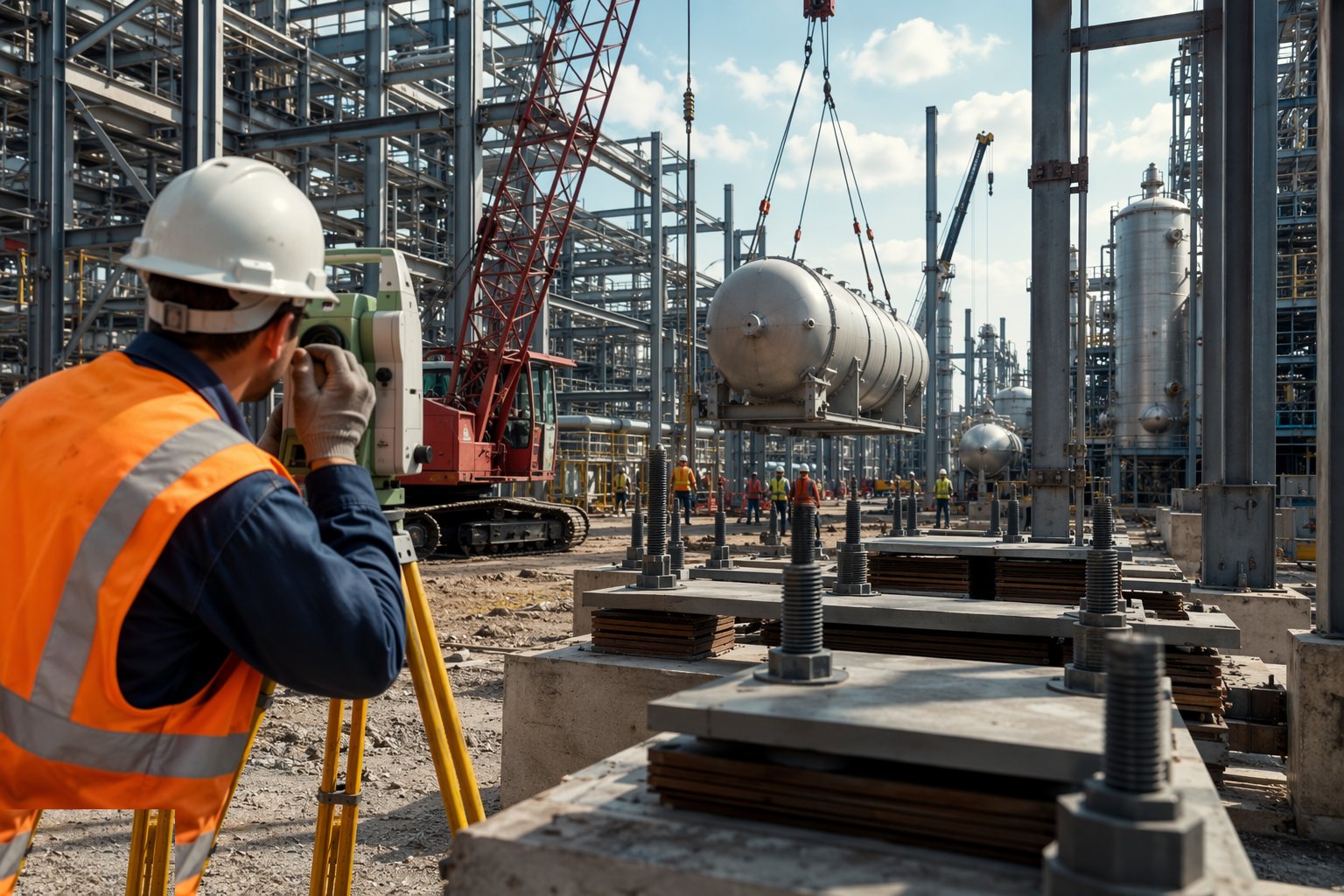
Take the foundation release certificates and re-verify: bolt positions, levels and the condition of the bearing surfaces. Set shim packs or level the nuts on adjustable bolt arrangements to the erection datum, so steel goes up plumb first time. Chase and clean grout bearing areas, and mark the foundation centrelines — the erection survey hangs off these, and discovering a bolt-group error with a column on the hook is the definition of a bad day.
Step 3: Erect the steelwork
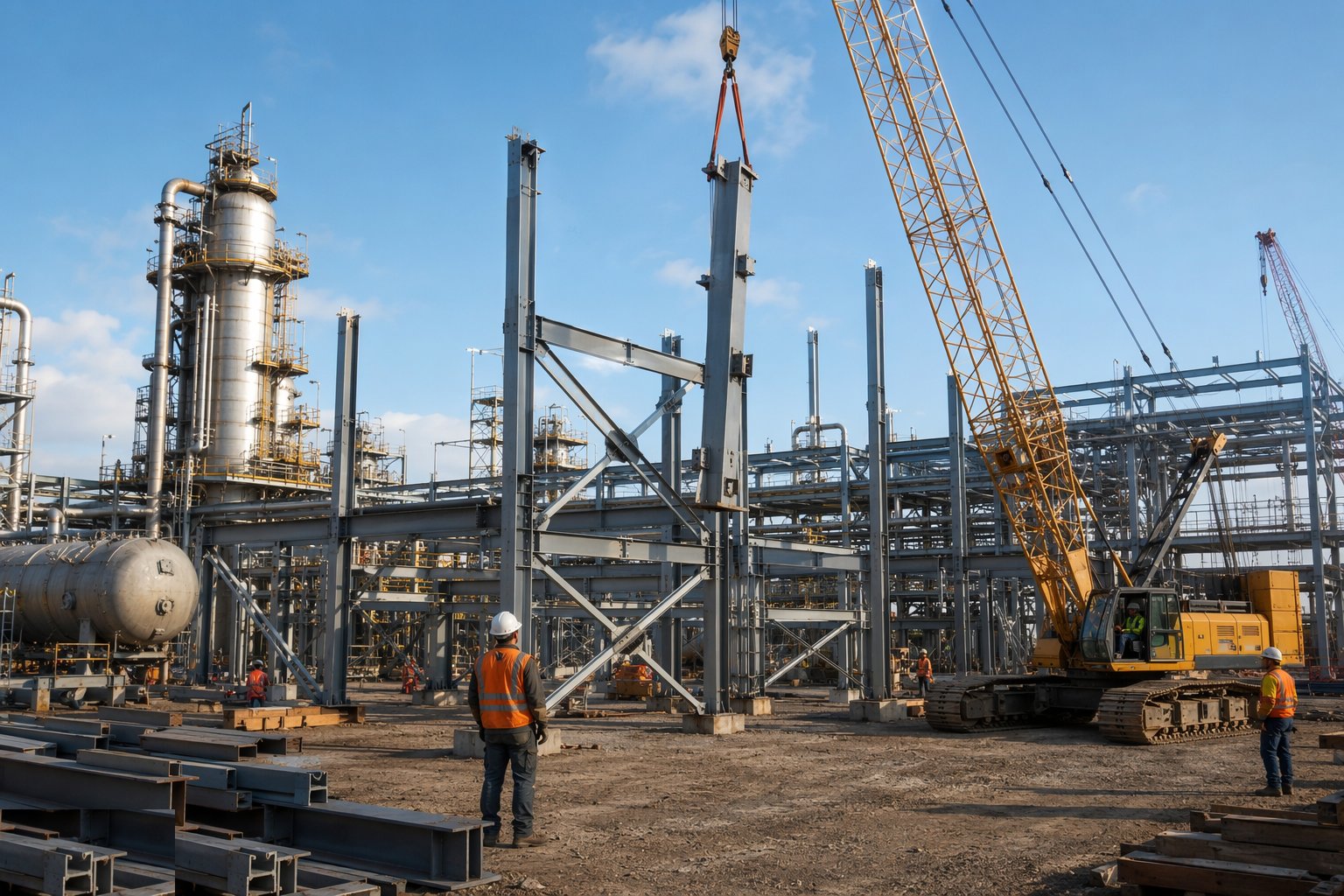
Erect in braced, stable bays — no leaving unbraced columns overnight — with connections made up to the specified bolt procedure: snug-tight or pre-loaded HSFG as designed, with the correct tightening method and traceable torque or tension records. Hold a plumbed-and-lined survey on each bay before releasing the crane; temporary bracing comes out only when the permanent stability system is complete. Coating damage is touched up as you go — it only gets harder to reach.
Step 4: Plan and approve the heavy lifts
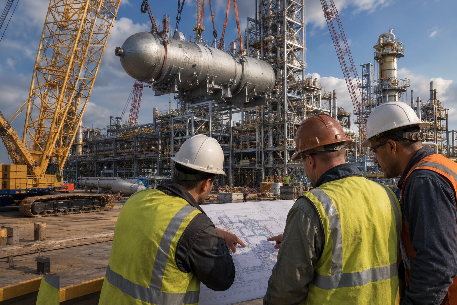
For every significant pick, the Appointed Person produces the lift plan to BS 7121 principles (or the operator's lifting standard): load weight and centre of gravity from certified data, crane selection and configuration checked against duty charts, ground-bearing calculations with mats or engineered crane pads, rigging design, wind limits, exclusion zones and the tailing method for vertical vessels. Complex lifts — tandem picks, lifts over live pipework, high-utilisation picks — get independent review. Nothing lifts until the plan is approved, the crane is certificated, the riggers are competent and the permit is live.
Step 5: Lift and set the equipment
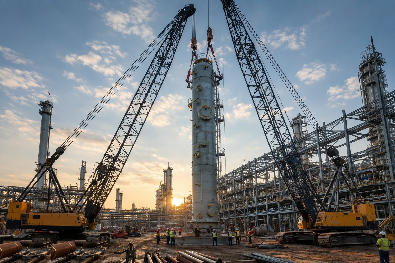
Execute the lift to the plan with the crane supervisor in control and the exclusion zone enforced. Land vertical vessels on the bolt circle, tail them up gently, and check plumbness at two elevations with the survey instrument before the crane is released; land horizontal equipment and machines on their prepared shims or sole plates and set level, line and elevation. Record every as-set survey — these are the numbers the piping spool design will assume.
Step 6: Align, grout and torque up
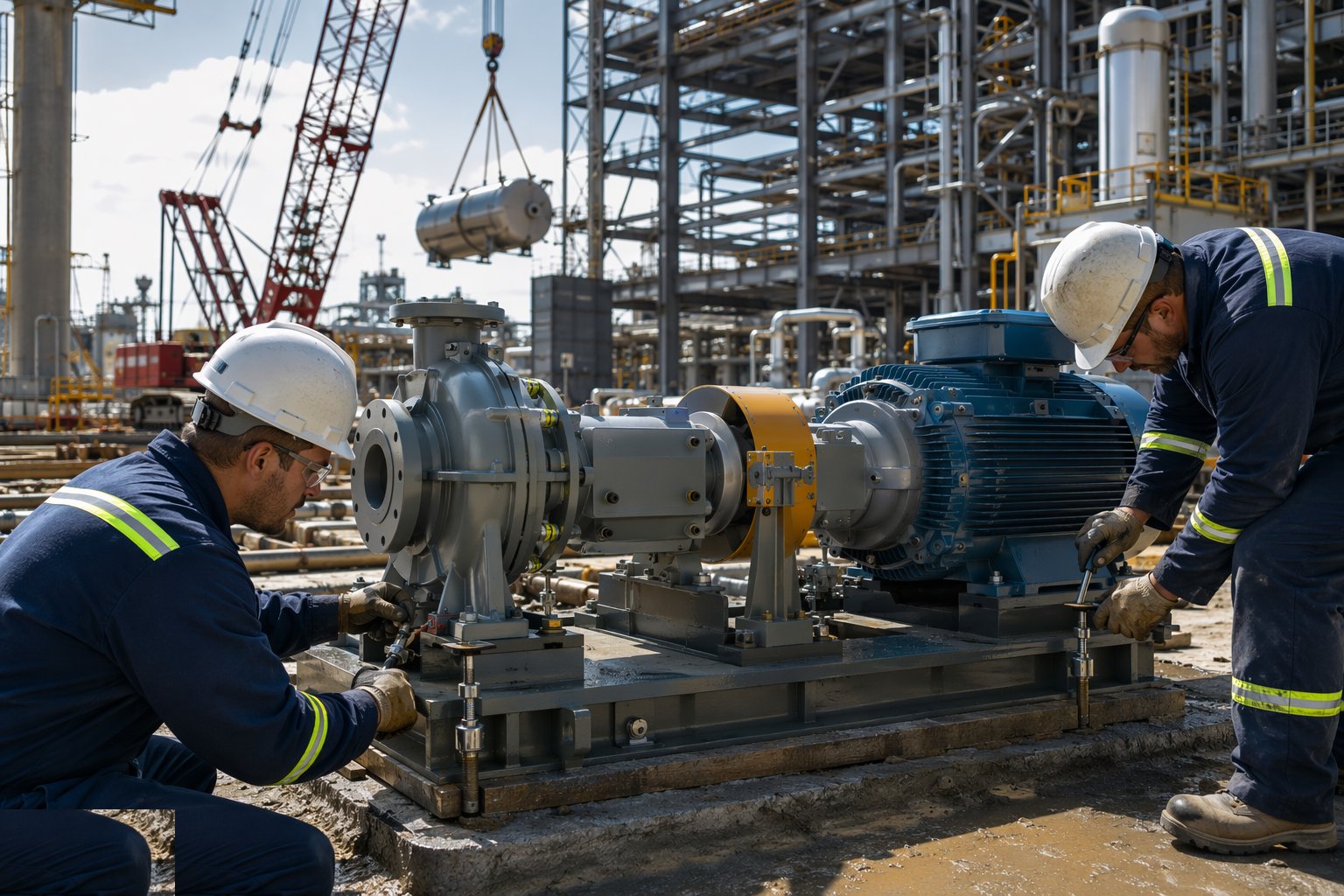
Complete the machine alignment — driver to driven unit — to the vendor's tolerances before piping forces are ever applied to the nozzles. Grout baseplates and sole plates with the specified non-shrink or epoxy grout, properly boxed and cured; grout failures under machinery are a classic source of soft-foot and vibration problems in service. Finally torque the anchor bolts and record the values, and touch up coating damage on steel and equipment.
Step 7: Hand over geometry to the piping stage
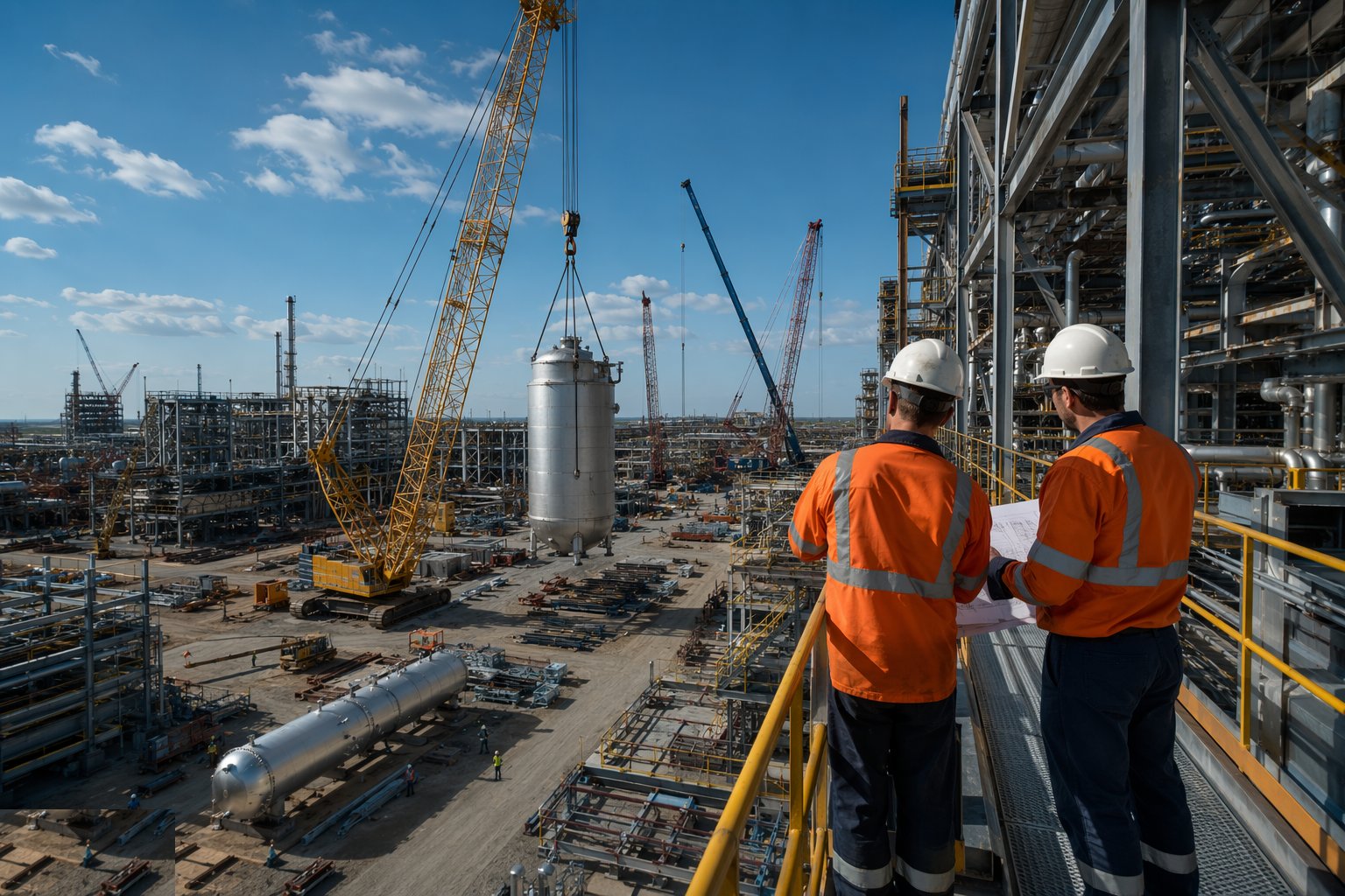
Compile the erection dossier: bay alignment surveys, equipment as-set records, bolt torque records, grout certificates and the punch list. Walk the structures and equipment with the piping and E&I leads so they take over a surveyed, documented plant — the nozzle orientations, rack elevations and machine positions in the dossier are what the spool fabrication and cable routing will be designed against. Deviations are declared now, engineered around on paper, not discovered at fit-up.
Plant and equipment
- Crawler cranes and heavy all-terrain cranes for major lifts
- Mobile cranes, telehandlers and MEWPs for steel erection
- Rigging: shackles, slings, spreader beams and tailing frames
- Torque wrenches, tensioners and HSFG bolt equipment
- Total stations and precision levels for alignment surveys
- Shim packs, sole plates, non-shrink and epoxy grouts
- Crane mats and engineered pad materials for ground bearing
- Tugger winches, chain blocks and alignment jacks
Quality control checks
- Material certificates and bolt-set traceability checked at receipt
- Foundation release certificates verified before any erection
- Bay-by-bay alignment survey before crane release
- Lift plans approved and categorised; crane certification and rigger competence on file
- As-set surveys for every vessel and machine, filed against tag number
- Bolt torque/tension records traceable to connection
- Grout specifications, batching and curing records for baseplates
- Coating damage logged and touched up before access is lost
Safety considerations
- Lifting operations planned to BS 7121; exclusion zones enforced during every pick
- Working at height on steel: fall arrest, MEWP access, edge protection on platforms
- Dropped-object prevention: tool lanyards, bolt baskets, no loose material on racks
- Crane ground-bearing and outrigger checks; no lifting outside the approved window
- Permit-to-work and lift-specific permits on operator sites; standby riggers
- Wind monitoring for tall vessel lifts — anemometer on the hook or crane
- Heat stress on steel decks in the Gulf summer; midday-break compliance
Common defects
- Steel erected out of plumb because shims were guessed, not surveyed
- Anchor bolts grouted before alignment was signed off — machine locked in wrong
- Lift executed outside the approved plan — different configuration, bigger radius
- Vessel set with nozzles out of orientation — piping spools no longer fit
- Soft foot under machinery from voids in the grout
- Coating damage left at height — corrosion starts before commissioning
- Crane pad placed over an unrecorded trench or soft spot — outrigger sinks mid-lift
- As-set survey skipped; piping fabrication proceeds on assumed positions
Best suited for
- Piperack and technological steelwork erected around the civils
- Heavy lifts landing vessels, columns and compressors
- Survey-controlled setting and grouting of rotating equipment
- Steel and equipment aligned to millimetre tolerances
How long does Structural Steel & Equipment Setting take?
Typical duration: Typically 4–8 months for the steel and major equipment setting on a process unit, paced by crane availability, equipment delivery and weather windows for the heavy lifts; modular Gulf projects compress the site phase sharply at the cost of a heavier lift campaign..