Grid Connections & Energisation
The paper-and-permit end of grid construction — connection agreements, protection witness tests, outages booked seasons ahead, and the phased switching sequence that puts a new asset on the live network.
Last updated 2026-07-28 by the BuildPedia Editorial Team.
What is Grid Connections & Energisation?
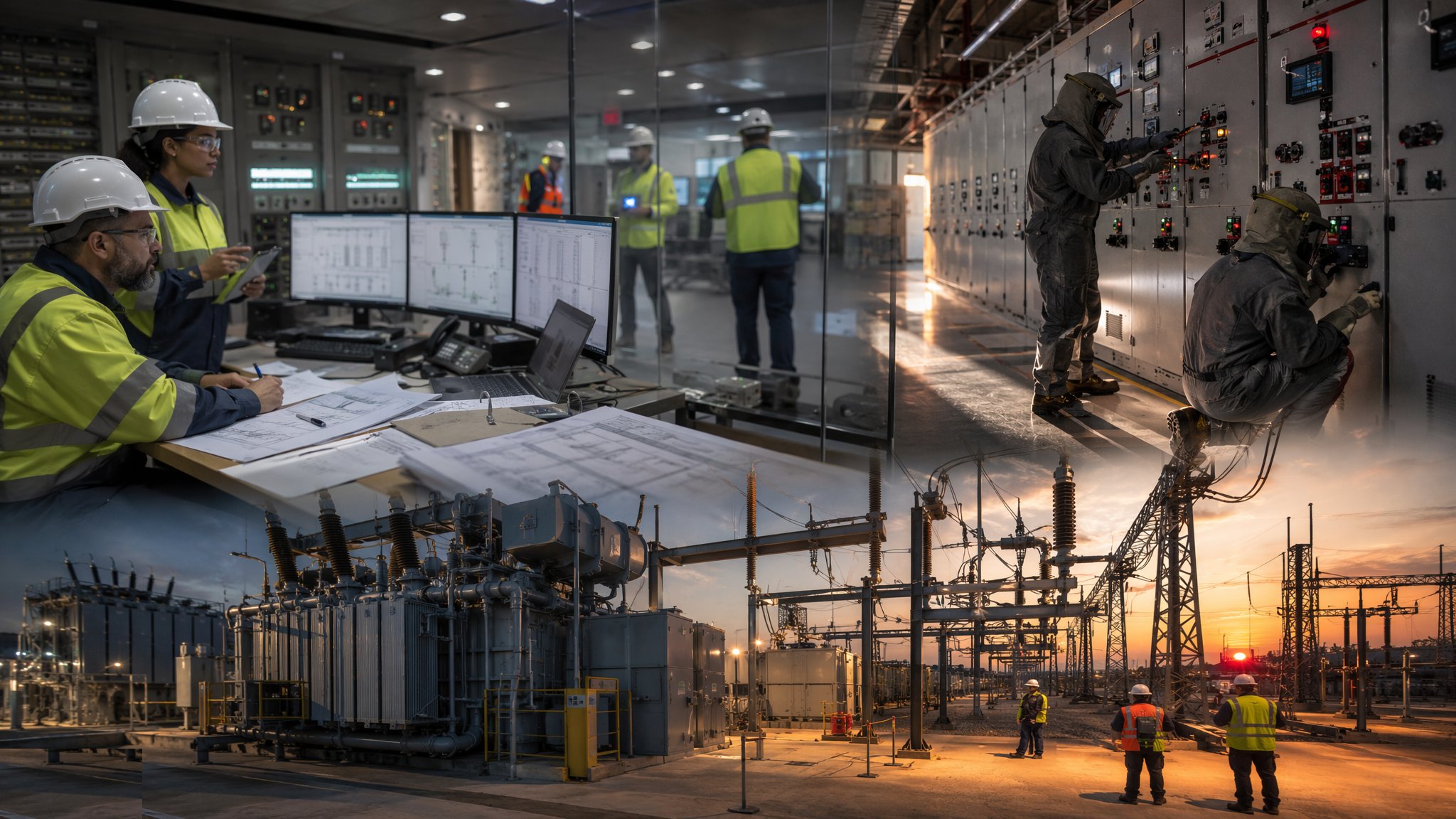
Energisation is the connection of a new substation, line or cable to the live network — the moment it stops being a construction site and becomes part of the grid. Everything in this sector exists for that one event, and it is the least physical process in the sector and the least forgiving. Before any switching, there is the connection framework: in the UK, a connection agreement with the distribution network operator or the transmission system operator, design approval of the interface, and increasingly contestable works where an Independent Connection Provider builds the assets and the DNO adopts them — competition in connections having moved much of this work from the incumbent to the market. In the UAE the route runs through the utility itself: DEWA's connection approvals in Dubai, the transmission company's in Abu Dhabi, with Civil Defence clearance a prerequisite before energisation. Either way, nothing connects until the paperwork says it may.
The technical gate is the protection and control proof. New plant cannot simply be switched in: its protection must be set, injected and witnessed — secondary injection through the relays with test sets proving every element operates at its settings, primary injection or ratio and polarity checks proving the CTs and VTs tell the relays the truth, trip circuits proven from relay to breaker, and intertripping and signalling proven end to end where the scheme demands it. SCADA points are verified point by point with the control room that will run the asset; metering is commissioned; and the network operator's witness signs the test records, because on first fault — which will come — the protection is the only thing between the network and a very bad day. Settings files are controlled documents: the wrong file version loaded into a relay is a mal-trip scheduled for a convenient future outage.
Energisation itself is choreographed. An outage of the connecting network is planned — on transmission, booked twelve to twenty-four months ahead around system demand — safety documents are issued under the operator's safety rules by its authorised staff: permits to work, sanctions for test, limitations of access, with the points of isolation established, circuit main earths applied, and every person on site briefed onto the document. The switching programme then runs in phases: auxiliary supplies first, then transformers energised and soaked, then circuits brought up, checks at every stage — voltages, phase rotation, protection stability — before the next step, and new cables and transformers commonly left on soak at voltage for a day before loading. When the last step closes, the asset is live, the permits are cancelled, and the handover file — test certificates, settings records, as-builts, O&M documentation — passes to the operator who will run it for the next forty years.
When and why is Grid Connections & Energisation used?
This process runs at the end of every grid construction project — the substation, line or cable that cannot energise is an expensive monument — and at every reinforcement or diversion that touches the live network. It matters because energisation is where construction risk meets network risk: a mistake here does not just damage the new asset, it can trip the existing network, black out customers who never heard of your project, and put the operator's system into states it was designed to avoid. That is why the process is rule-bound to its fingertips: the safety rules, the authorised persons, the witness signatures and the outage planning exist because the grid forgives nothing. For the contractor, the lesson is that energisation cannot be compressed at the end: witness slots, outage windows and authorised staff are the scarcest resources on the project, and the programme that treats them as available on demand finishes late.
Types of Grid Connections & Energisation
New grid supply points and transmission connections
New substations and circuits connecting at 132 kV and above, with the transmission operator's design approval, interface protection, and outages planned around system demand seasons. The longest-lead, most formal end of the game — and the one where a missed outage window can cost a year.
Distribution connections and diversions
Connections at 33 kV and below: new load feeds, network diversions around development, reinforcement of existing feeds. Higher volume, shorter outages, but the same discipline — permits, witnessed protection, and switchgear that must operate right first time.
Contestable connections (ICP works)
The UK competition-in-connections market: an Independent Connection Provider designs and builds the contestable scope, the DNO or an independent network operator adopts it after technical acceptance. The energisation is the adoption gate — self-monitoring records, witnessed tests and the operator's acceptance process replacing the incumbent's direct control.
Generation and storage connections
Connections that export: solar farms, wind, batteries and embedded generation, with grid code compliance, export limitation schemes and protection that must behave in both directions. The witness testing is heavier, the settings more argued over, and the compliance evidence part of the connection agreement.
Grid Connections & Energisation: step by step
Step 1: Secure the connection agreement and design approval

Long before site, the connection framework is fixed: the connection agreement with its technical appendix, the interface design approved by the network operator, protection philosophy and settings agreed, and the adoption or vesting arrangements settled where an ICP or third party builds the assets. This is where energisation problems are prevented or booked: a protection philosophy disputed at witness-test stage was lost here, and an outage requirement discovered after the civils are done is a programme disaster with a date stamp. In the UAE, the equivalent approvals run through DEWA or the emirate's utility with Civil Defence clearance in the chain — and every one of them has a queue.
Step 2: Plan outages and safety co-ordination
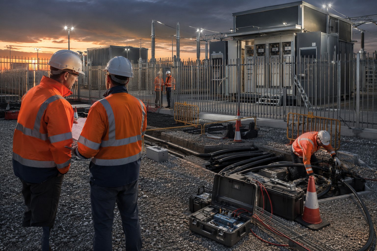
The outage programme is negotiated with the operator's system control: which circuits can come out, when, for how long, and in what sequence — on transmission, booked a year or more ahead around demand and other planned work. The safety co-ordination is designed alongside: points of isolation, earthing arrangements, the safety documents each work stage needs, and the authorised persons — the senior authorised person and their team — who will issue and control them. Construction sequencing is then bent to fit the outages, not the other way round: the site that plans its programme first and asks for outages second learns the correct order at some cost.
Step 3: Complete pre-commissioning and protection proving
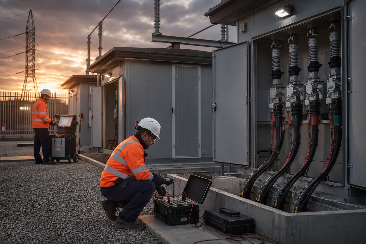
Before any outage is spent, the new plant is proven dead-side: secondary injection through every protection relay against the agreed settings, CT and VT ratio and polarity proven, trip and close circuits operated from relay to breaker, breaker timing and contact tests done, intertripping and signalling proven end to end, and the battery and DC systems load-tested. Every result is recorded on the test schedules that the operator's witness will examine. The rule of this stage is absolute: nothing is left to be discovered on the outage. The outage is for connecting proven plant, not for commissioning it.
Step 4: Witness tests and SCADA point-to-point with the operator
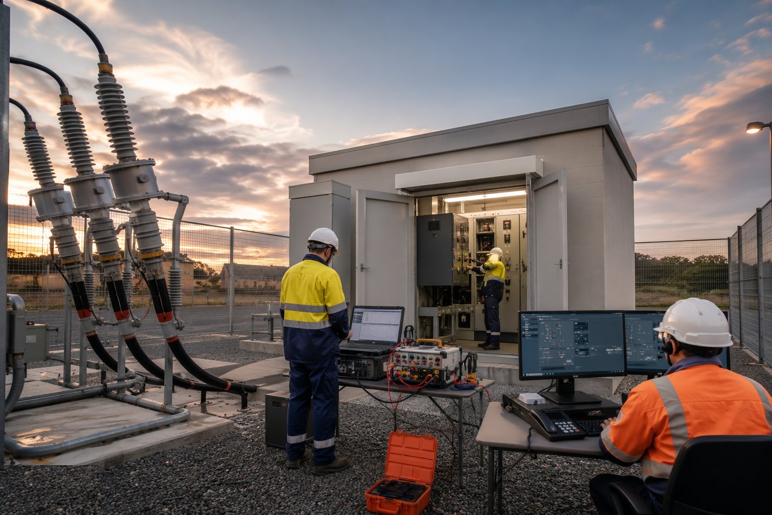
The network operator's engineers witness the tests that matter to them: protection operation at settings, trip paths, SCADA point-to-point — every analogue and status point exercised at the plant and confirmed at the control room, every control command issued and observed. Metering is commissioned and proven. The witness records are signed there and then, because an unsigned witness sheet is a test that never happened as far as the operator is concerned. Where faults are found — a mapped SCADA point, a reversed CT — they are fixed and re-witnessed before the outage, because the control room's picture of the network must be the truth from the first second the asset is live.
Step 5: Execute the phased energisation under safety documents
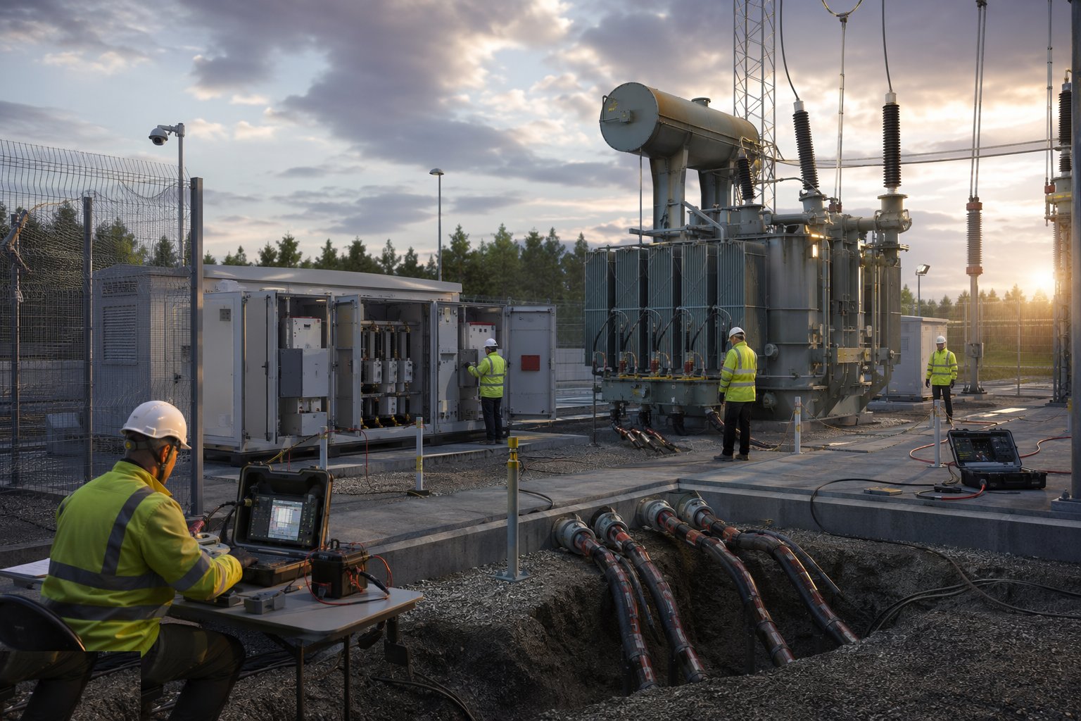
On the outage, the operator's authorised staff run the show: isolations established and proven, circuit main earths applied, safety documents issued, and the physical connections made under permit. Then the switching programme runs in its written order — earthing removed in sequence, auxiliaries energised first, transformers energised and checked for inrush and stability, circuits energised one at a time with voltage, phase rotation and protection stability checks between steps, and new cables and transformers left on soak at voltage before load is applied. Every step is logged against the programme; any anomaly stops the sequence. Nobody improvises on an energisation — the switching schedule is flown like a flight plan, by the people authorised to fly it.
Step 6: Post-energisation checks, soak and load ramping
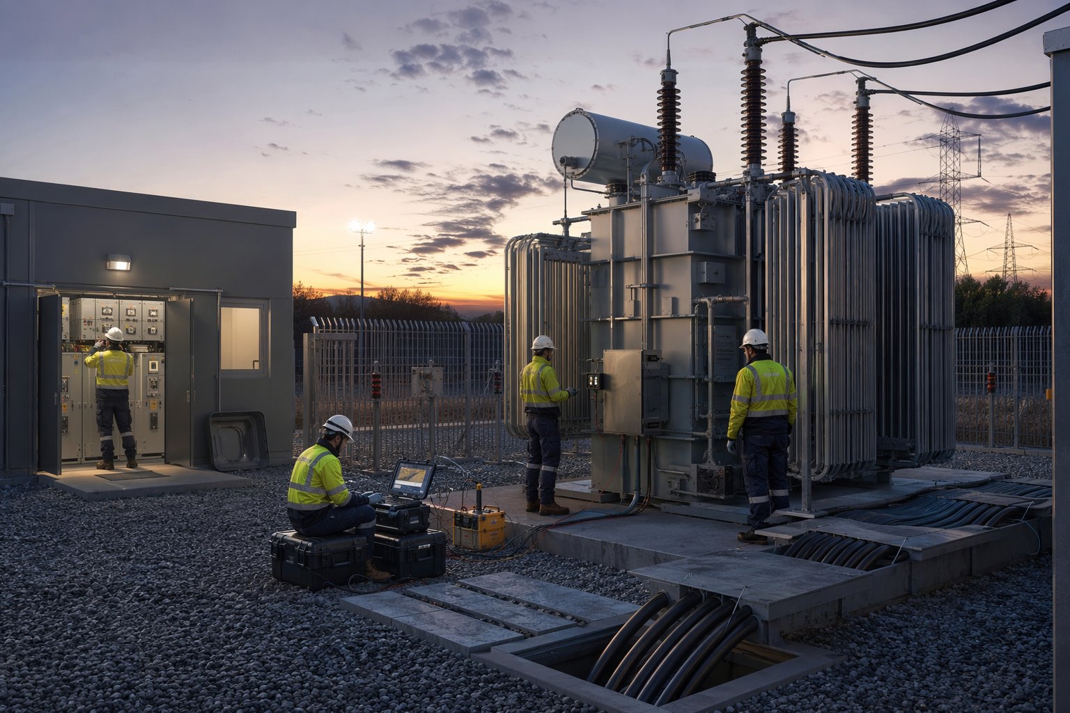
Live does not mean finished. Soak periods are monitored — temperatures, gas pressures, oil condition with dissolved gas analysis on transformers — and load is applied in stages where the connection agreement requires it, with protection stability re-verified under real load current and metering proven against the control room's readings. On-load tests complete the picture: tap changer operation, auto-changeover schemes, export limitation where fitted. The asset is watched through its first days and weeks on load, because commissioning defects on grid plant announce themselves under load, not at the ribbon-cutting.
Step 7: Hand over, vest and close the file
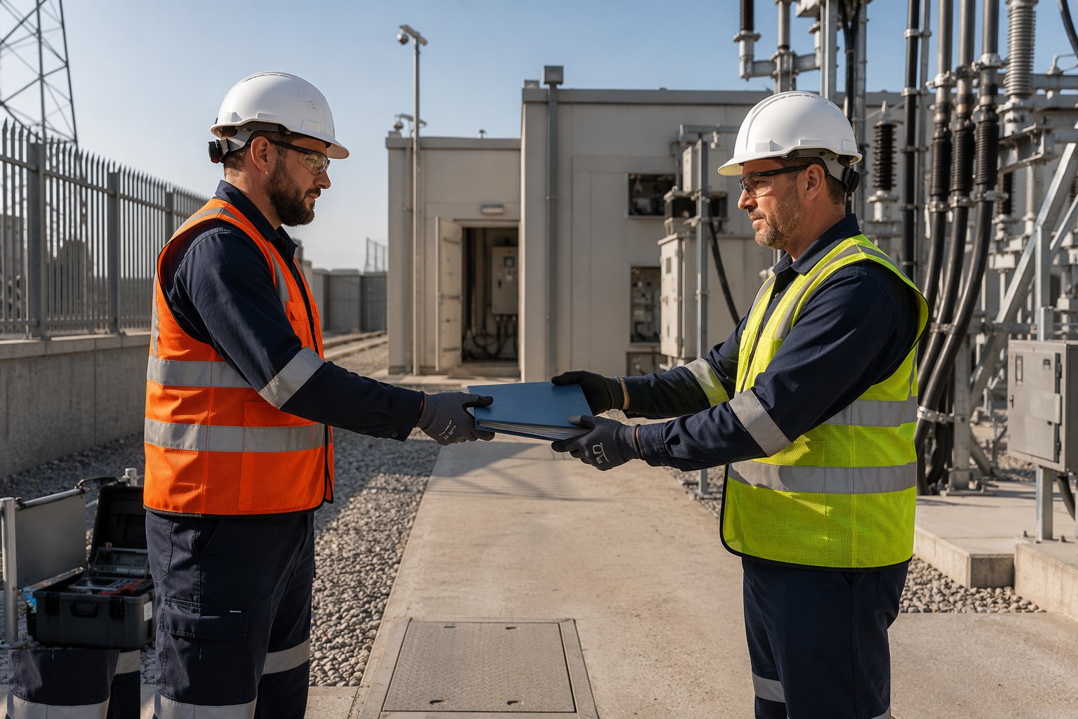
The final act is documentary: the complete handover file to the operator — test certificates and witness records, protection settings as left, SCADA schedules, as-built drawings, cable and joint records, O&M manuals and spares schedules — and the adoption or vesting paperwork executed where the assets change ownership. Defects and snagging lists are agreed and closed, retention and warranty clocks start, and the construction team stands down. What remains is a line on the control room diagram and an asset the operator must trust in the dark in a storm — which is exactly why every signature in the file mattered.
Plant and equipment
- Secondary injection test sets (three-phase relay test equipment) for protection proving
- Primary injection sets and CT/VT test equipment for ratio and polarity
- Circuit breaker analysers — timing, contact resistance and travel
- SCADA test and marshalling equipment for point-to-point verification
- Portable earthing equipment, voltage detectors and proving units for the safety regime
- Transformer oil sampling and DGA analysis arrangements for soak monitoring
- Load banks where on-site load proving is required
- Document control systems for settings files, test schedules and witness records
Quality control checks
- Protection settings controlled as issued documents — the version in the relay proven against the agreed schedule
- Secondary and primary injection records per relay and CT/VT, signed and filed
- Trip and intertrip proven end to end; breaker timing and contact results within manufacturer limits
- SCADA point-to-point schedules 100% complete and witness-signed — no exceptions
- Switching programme and safety document records for the energisation itself, logged step by step
- Handover file complete: certificates, as-left settings, as-builts, O&M and adoption/vesting documents
Safety considerations
- The operator's safety rules govern everything on or near live plant: permits to work, sanctions for test, limitations of access — issued only by authorised persons
- Points of isolation proven dead before work: test before touch, with proven voltage detectors and applied earths
- Back-feed and generation risk: connections that can energise from either end treated as live from both until proven
- Stored charge: cables and capacitor equipment hold lethal charge after isolation — discharge, earth and wait per the rules
- Induction on parallel circuits: additional earths at the work site, never trust a line to be dead because it was switched
- Switching operations only by authorised staff to the written programme — one wrong operation on a live network is a career and a headline
Common defects
- Wrong settings file loaded into a relay — protection that mal-trips on first load or first fault
- CT polarity reversed or ratio mismatched — differential and directional schemes defeated silently until the fault arrives
- SCADA points mis-mapped — the control room watching the wrong breaker and commanding the wrong plant
- Phase rotation errors discovered at paralleling — the switching programme stopped with the outage clock running
- Inadequate earthing or missed isolation points during the works — the near-miss that ends careers
- Handover documentation gaps — unsigned witness records and missing certificates delaying adoption and energisation alike
Best suited for
- Every new substation, line and cable at the point it meets the live network
- ICP-built contestable connections passing technical acceptance for adoption
- Generation and storage connections with grid code compliance evidence to prove
- Network diversions and reinforcements executed inside outage windows
How long does Grid Connections & Energisation take?
Typical duration: Witness testing and point-to-point typically run two to six weeks per substation; transmission outage windows are booked twelve to twenty-four months ahead; from connection agreement to energised, adopted asset, the full connection process commonly spans one to three years..