Underground Cable Installation
High-voltage circuits buried in trenches and duct banks — kilometres of XLPE cable pulled between joint bays, bedded in thermal surround, jointed by certified jointers, and proven by the sheath test.
Last updated 2026-07-28 by the BuildPedia Editorial Team.
What is Underground Cable Installation?
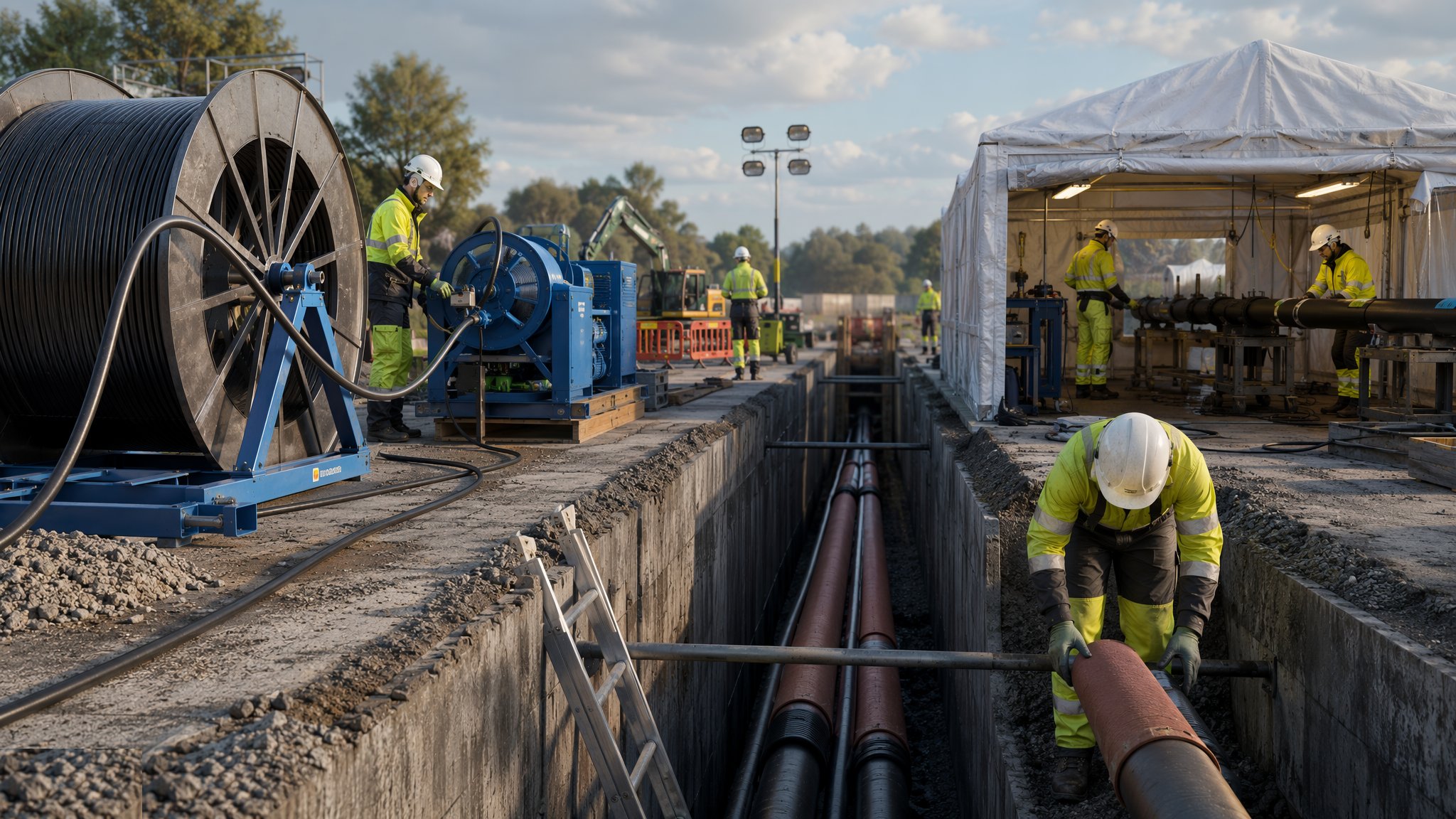
Where overhead lines cannot go — cities, crossings of protected land, connections into substations — the circuit goes underground. High-voltage cable is a precision product installed by a groundworks industry: single-core XLPE cables for transmission voltages, three-core for distribution, delivered on drums weighing tens of tonnes and laid in trenches or duct banks with joint bays every few hundred metres where drum lengths run out. The trench is an engineered structure, not a slot in the ground: designed depth and formation, bedding under the cables, a thermal surround — fluidised thermal backfill or cement-bound sand with a certified thermal resistivity — because a buried cable's entire current rating depends on how well the backfill conducts its heat away, and cable covers and marker tape above, warning the next hundred years of excavators. The route's as-built record is part of the asset: GPS-surveyed positions and depths, because a cable nobody can find is a cable somebody will strike.
Installation is tension management again, but horizontally. Cables are pulled from the drum through the trench or duct on rollers, by winch with a bonded pulling eye or stocking grip, with the pulling tension and sidewall pressure at bends monitored against the manufacturer's limits and the minimum bending radius respected everywhere — an overstretched conductor or a kinked cable is scrap on a drum you cannot return. Ducted routes are proven before the cable arrives: every duct mandrel-tested end to end, because a duct that will not pass its proving mandrel will not pass a cable, and finding that out with the drum on site is a very expensive education. Joint bays — oversized excavations, often shuttered and floored, with welfare and weather protection — give the jointers room to work, and the joint itself is the highest-skill event of the job: certified jointers preparing the cable ends, stripping and chamfering the insulation screen to exact geometry, shrinking or moulding the joint on, and recording every material batch and step, because a joint buried wrong fails in service and its excavation at 132 kV is a six-figure event.
The electrical design touches the ground in the sheath system. Single-core transmission cables carry induced voltages on their metallic screens, managed by cross-bonding — the sheaths transposed and earthed through link boxes at joint bays, with sheath voltage limiters protecting the system — and the outer sheath's integrity is proven by test after backfill: a DC voltage test between the metallic screen and earth, typically 10 kV for one minute on new installations, on every section. A sheath punctured by a stone during laying or a clumsy backfill fails that test, and the repair is a joint where nobody planned one. In the UAE, DEWA's 132 kV network is substantially underground by policy — the desert city runs on buried cable — so the thermal design against hot, dry sand and the discipline of duct banks and joint bays are everyday practice, with authority inspections at the same hold points the UK network operators use.
When and why is Underground Cable Installation used?
Cable is chosen where overhead is impossible or refused — urban routes, crossings under approach surfaces and protected landscapes, the final connections into substations, and in the Gulf as the default for the whole distribution network. It matters because underground circuits are invisible and unforgiving: an overhead fault is found by looking; a buried cable fault is found by fault-location equipment and fixed by excavation. That invisibility raises the stakes on every construction record — the as-built route, the joint locations, the sheath test certificates — because the network operator inherits an asset it cannot see and must trust the file. For the contractor, the economics live in re-excavation avoided: every duct proven, every pulling tension logged, every backfill certificated, because every shortcut is buried with the cable and bills come due with interest.
Types of Underground Cable Installation
Direct-buried circuits
Cables laid straight into the trench on bedding, surrounded with thermal backfill, protected by covers and marker tape. The cheapest installation per metre and the standard in open country — with the trade-off that any future repair or diversion means digging the road or the field again.
Ducted circuits and duct banks
Cables drawn through ducts — single ducts or multi-way banks in concrete surround — with draw pits and joint bays along the route. More civils up front, but cables can be replaced or added without new excavation: the urban standard, and the only civilised answer under carriageways.
Cable tunnels, troughs and bridges
Where routes converge — substation approaches, river and rail crossings — cables run in purpose-built tunnels, surface troughs with lids, or on bridge structures. Accessible, inspectable, and built like the structures they are: fire protection, ventilation and drainage included.
Cross-bonded single-core EHV systems
The transmission-voltage arrangement: single-core cables with metallic screens cross-bonded through link boxes in minor and major sections, sheath voltage limiters at the unearthed ends. The joint bay becomes an electrical chamber, and the sheath integrity test the defining acceptance event.
Underground Cable Installation: step by step
Step 1: Prove the route: trial holes, clearance and setting out
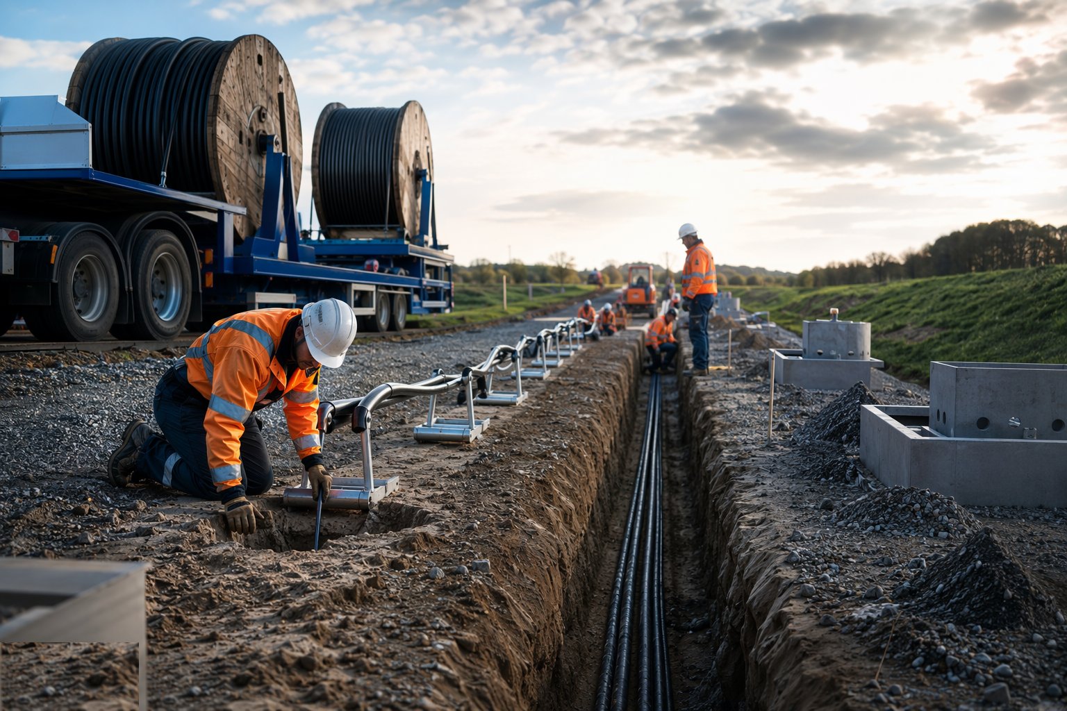
The route is scanned and trial-holed against every utility record — HSG47 discipline in the UK, service NOCs in the UAE — because a cable trench shares the corridor with gas, water, fibre and older power cables, and trial holes are where you meet them on your terms. The alignment is set out with joint bay positions fixed by the drum schedule — you order cable lengths against the route, not the other way round — and depths are planned to keep clearances from other services and to hold the rating the thermal design assumed. Traffic management and possession bookings in live streets are part of the route design, not an afterthought.
Step 2: Excavate the trench and install the duct bank
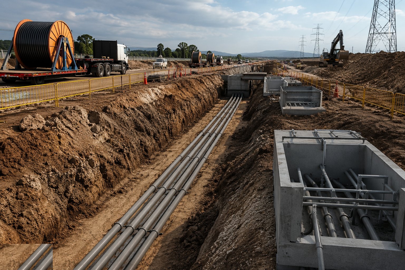
The trench is cut to the designed depth and width with support where men enter, the formation trimmed and blinded or bedded to detail. Ducts are laid to line and gradient on spacers in multi-way banks, jointed and rodded as they go, then surrounded with concrete where the design calls for it — and every duct is mandrel-proved end to end before acceptance. Joint bay excavations go in at their scheduled positions, sized for the jointers to work around the cable ends, with sumps, shuttering and edge protection. Water in the trench is pumped out before bedding — cable laid into a flooded trench is cable laid blind.
Step 3: Pull and lay the cable
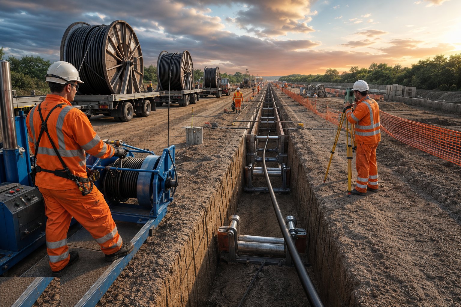
Drums are set on stands or trailers at the pulling end, the winch and pulling rope rigged, rollers set through the trench and at every bend, and the cable is pulled with tension monitored at the winch and logged — against the calculated maximum pulling tension and the sidewall pressure limits at bends, with the minimum bending radius policed by men who know what a kink costs. The cable is laid into its bedding position, straight and untwisted, with expansion snaking where the design calls for it. At the joint bays, the cable ends are left with their overlap, capped and protected, and every metre laid is recorded against the as-built survey before anything is covered.
Step 4: Backfill with bedding, thermal surround and protection
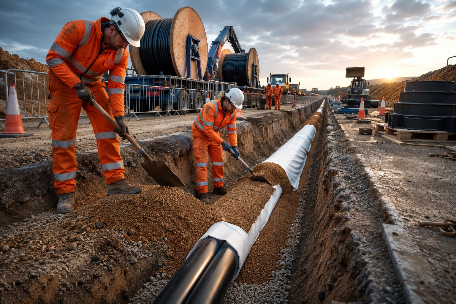
Backfill is a specified material operation, not muck-shovelling: bedding placed around and over the cables without voids, the thermal surround — fluidised thermal backfill or cement-bound sand with certified thermal resistivity — placed to its designed envelope, then protective covers and marker tape set above the cables at their specified depth before general backfill and reinstatement. Every delivery of thermal surround is certificated, because the difference between the specified resistivity and whatever came off the lorry is the circuit's current rating for the next forty years. Compaction under carriageways follows the reinstatement specification, and the whole cross-section is recorded on the as-built as each length is closed.
Step 5: Joint the sections and fit link boxes
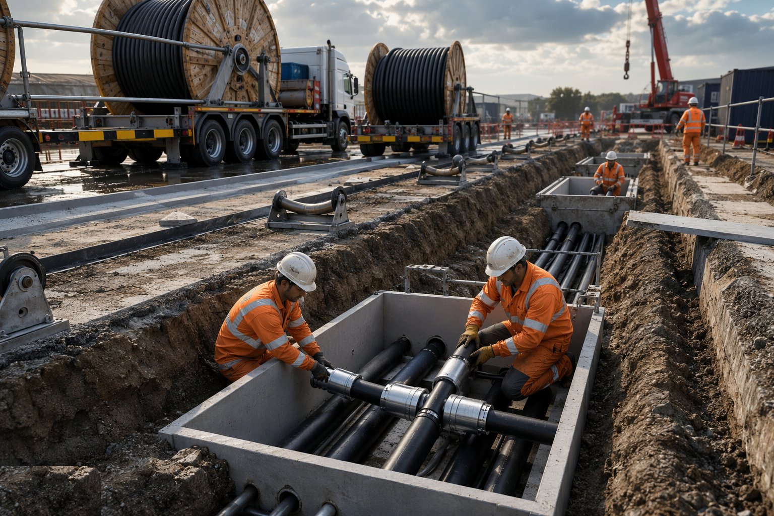
Jointing is the craft centre of the job. Certified jointers work in the bays under weather protection and cleanliness control: cable ends prepared to the joint manufacturer's dimensions, insulation screen stripped and chamfered to exact geometry, connectors compressed, the joint body shrunk or moulded on, screens connected through the cross-bonding leads, and the outer protection restored. Every joint is logged — jointer, date, materials batches, dimensions — on the joint record that follows the asset for life. Link boxes are mounted in their chambers with the cross-bonding connected per the phasing schedule, sheath voltage limiters fitted, and the chamber finished and drained.
Step 6: Test the sheath and commission the circuit
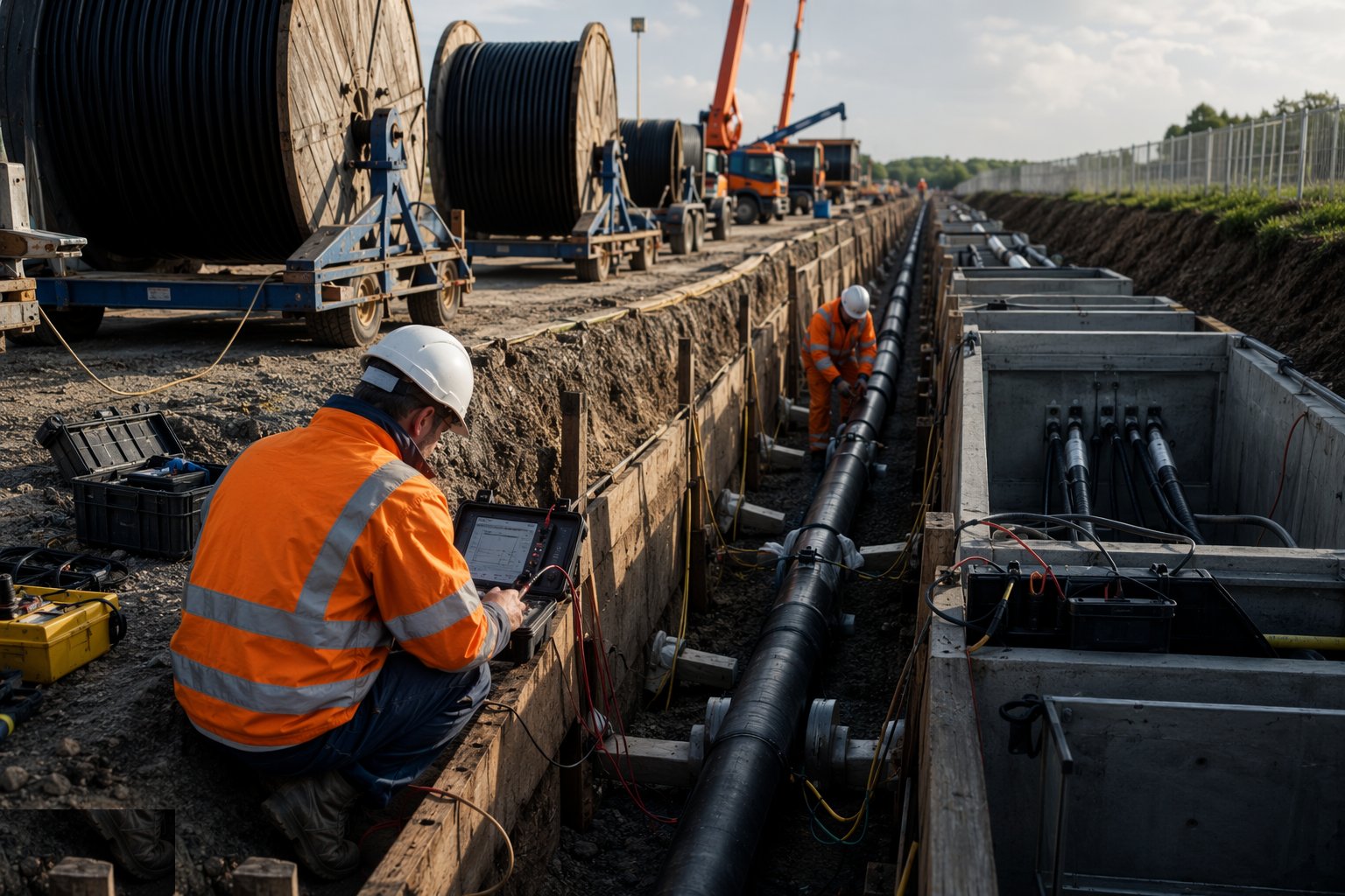
With backfill complete, the sheath integrity test proves the installation: DC voltage applied between the metallic screen and earth — typically 10 kV for one minute on new circuits, per the cable specification — on every bonded section, with failures located and excavated. Conductor continuity, phase identification and the cross-bonding arrangement are proven through the link boxes. Then the circuit passes to the network operator's commissioning regime — high-voltage withstand or soak arrangements per their policy, protection and SCADA integration at the ends — and the file is handed over: as-builts with GPS positions and depths, pulling logs, joint records, thermal surround certificates and sheath test certificates. The trench has healed over; the paperwork is the circuit's memory.
Plant and equipment
- Excavators, trench support and pumps for trench and joint bay excavation
- Cable drum trailers, stands and hydraulic jacks; drum handling cranes
- Pulling winches with tension monitoring and logging; pulling eyes, grips and swivels
- Cable rollers, bend radius formers and duct rodding/mandrel proving kit
- Concrete and fluidised thermal backfill supply and placement equipment
- Jointing equipment: preparation tools, compression presses, heat-shrink torches and joint manufacturer kits
- DC sheath test sets and cable fault location equipment
- GPS survey equipment for as-built route and depth records
Quality control checks
- Duct proving certificates — mandrel passed end to end on every duct before cable
- Cable pulling logs: tension and speed recorded per pull against calculated limits
- Thermal surround and bedding certificates with thermal resistivity compliance per delivery
- As-built survey: GPS position, depth and cross-section recorded before backfill closes each length
- Joint records per joint — certified jointer identity, dimensions, material batches — filed to the asset
- Sheath integrity test certificates per bonded section, with failures located, repaired and retested
Safety considerations
- Buried services in a shared corridor: scan, trial-hole, hand-dig at crossings — the strike you avoid is the one you planned for
- Trench and joint bay collapse: support, batter or bench, ladder access, spoil and plant back from edges
- Cable drums: tens of tonnes that roll — chocked, jacked on level ground, never worked downhill of
- Pulling operations: ropes and bonds under tension, snap-back zones barricaded, communication between winch and drum continuous
- Live cables in shared trenches and bays: treated live until proven dead by the operator's own staff
- Deep joint bays as confined spaces where depth and gas risk demand: monitoring, ventilation and rescue arrangements
Common defects
- Ducts blocked or deformed at bends — mandrel fails, sections abandoned, and the route redesigned at duct bank prices
- Sheath damage during pulling — stones, roller failures, gouges — found at the sheath test with the road reinstated above
- Wrong or unblended backfill — thermal resistivity off spec and the circuit quietly derated for life
- Depth or position off the design — cables too shallow, unprotected, or outside the wayleave, found by the next excavator
- Joint defects from poor screen preparation or contamination — in-service failures excavated at six figures each
- Cross-bonding or phasing errors at link boxes — circulating currents, hot sheaths, and induced voltage where none should be
Best suited for
- Urban and suburban networks where overhead lines are impossible or refused
- Crossings of protected land, approach surfaces and constrained corridors
- Substation approaches and the final connections of overhead routes
- Gulf-style fully underground distribution networks in hot climates
How long does Underground Cable Installation take?
Typical duration: Open-country trench and lay runs at 100–300 m per week per crew, urban ducted routes slower against traffic management; each joint bay with its joints takes three to five days — a 10 km double-circuit 132 kV route typically takes nine to eighteen months including testing..