Substation Construction
The fenced compounds where voltage changes hands — air-insulated or gas-insulated switchgear, transformers the size of houses, and a buried copper earth grid that has to be right before anything else is built.
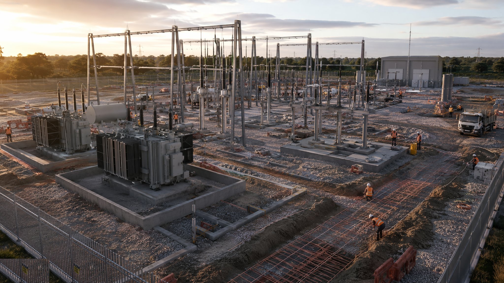
Last updated 2026-07-28 by the BuildPedia Editorial Team.
What is Substation Construction?
A substation is where the grid changes gear: transmission voltage arrives, transformers step it down, and switchgear routes it out to the next network. They come in two physical families. Air-insulated substations (AIS) are the outdoor compounds everyone knows — steel gantries carrying busbars overhead, circuit breakers, disconnectors and instrument transformers standing on plinths in rows, everything separated by air clearance distances the design code dictates, so the compound is big. Gas-insulated substations (GIS) pack the same switchgear into sealed, SF6-gas-filled modules inside a building, shrinking the footprint to a fraction — the default where land is expensive or the neighbours are close, which in practice means most new urban substations in the UK and almost everything in the Gulf's cities. The electrical design follows BS EN 61936 for installations above 1 kV; the equipment itself — transformers to the IEC 60076 family, switchgear to IEC 62271 — arrives from a handful of global manufacturers on lead times measured in many months, which drives the whole programme.
The civils are honest but unforgiving, and they start with the one element nobody will ever see again: the earthing grid. Before any foundation, a buried mesh of copper conductor is laid across the whole compound, joints brazed or exothermically welded, earth rods driven at the perimeter and around the transformer, and the whole thing tested — because its job is to keep touch and step voltages survivable when a fault dumps thousands of amps into the ground. UK practice works to BS EN 50522 and the Energy Networks Association technical specifications; every joint is recorded before backfill because digging the grid up to find a bad joint afterwards is a story nobody wants to tell. Then come the plinths and foundations — transformer plinths with their rails and oil containment bunds sized to hold the full oil volume, breaker and disconnector plinths set to tight level tolerances, gantry leg foundations, and the cable trench network threading the compound with its falls, covers and fire-stopped entries into the control building.
The heavy moment is transformer delivery: a grid transformer is a 100–300-tonne load arriving on a multi-axle trailer or self-propelled modular transporter, routed under bridge-strength assessments, jacked or skated off onto its plinth, then dressed with radiators, bushings and conservator, oil-filled or oil-processed under vacuum, and left to settle before test. Around it the switchgear is erected — AIS gear bolted together in the open and torqued joint by joint, GIS modules landed inside their building and gas-filled — and the control and protection building fills with relay panels, batteries, SCADA and telecontrol. In the UAE, DEWA's 132/11 kV distribution substations are a standardised product built by the hundred, and the energisation sequence is gated by Civil Defence clearance and DEWA's own inspections — the civils contractor who treats a substation as a concrete yard with a fence discovers otherwise at handover.
When and why is Substation Construction used?
Substations are built where load grows — a new city district, a data centre campus, a gigafactory, a housing programme that needs its own 33/11 kV injection — or where generation connects and the network needs a grid supply point. They matter because they are the nodes the network cannot lose: a grid substation fault blacks out a town, so everything about the build is biased to reliability — proven equipment, witnessed tests, an earthing system built like the insurance policy it is. For the construction team, the defining reality is sequencing: the earth grid before the civils, the civils before the heavy plant, the heavy plant before the secondary systems, and all of it often metres from live circuits in an existing compound, working under the network operator's safety rules with outages booked seasons ahead. The substation that energises late does not just delay a project — it delays everything downstream that was promised power.
Types of Substation Construction
Air-insulated outdoor substations (AIS)
The traditional open compound: gantry structures, air clearances, plinth-mounted breakers, disconnectors, CTs and VTs, and busbars strung overhead. Big footprint, honest construction, every connection visible and maintainable — the default where land allows, from 33 kV distribution sites up to 400 kV transmission compounds.
Gas-insulated substations (GIS)
Switchgear sealed in SF6-insulated modules inside a building, with cable or short busbar connections in and out. A fraction of the AIS footprint — the urban and Gulf default — trading civil simplicity for strict gas handling, cleanliness discipline during assembly, and dependence on the manufacturer's modules arriving right.
Distribution substations and package units
The 33/11 kV and 11 kV/LV end of the network: compact compounds with a ground-mounted transformer and ring main or packaged switchgear, built by the hundred to standard DNO designs — and in Dubai, DEWA's standardised 132/11 kV substation format. Repetition is the game: get the standard details right once, then hold them for a programme.
Grid supply points and transmission substations
The big nodes — 132 kV and above — with multiple transformers, busbar sections, and protection schemes that assume failure and plan around it. Long programmes, heavyweight plant, and commissioning that involves the transmission operator's own engineers at every witness point.
Substation Construction: step by step
Step 1: Establish the site, drainage and compound platform
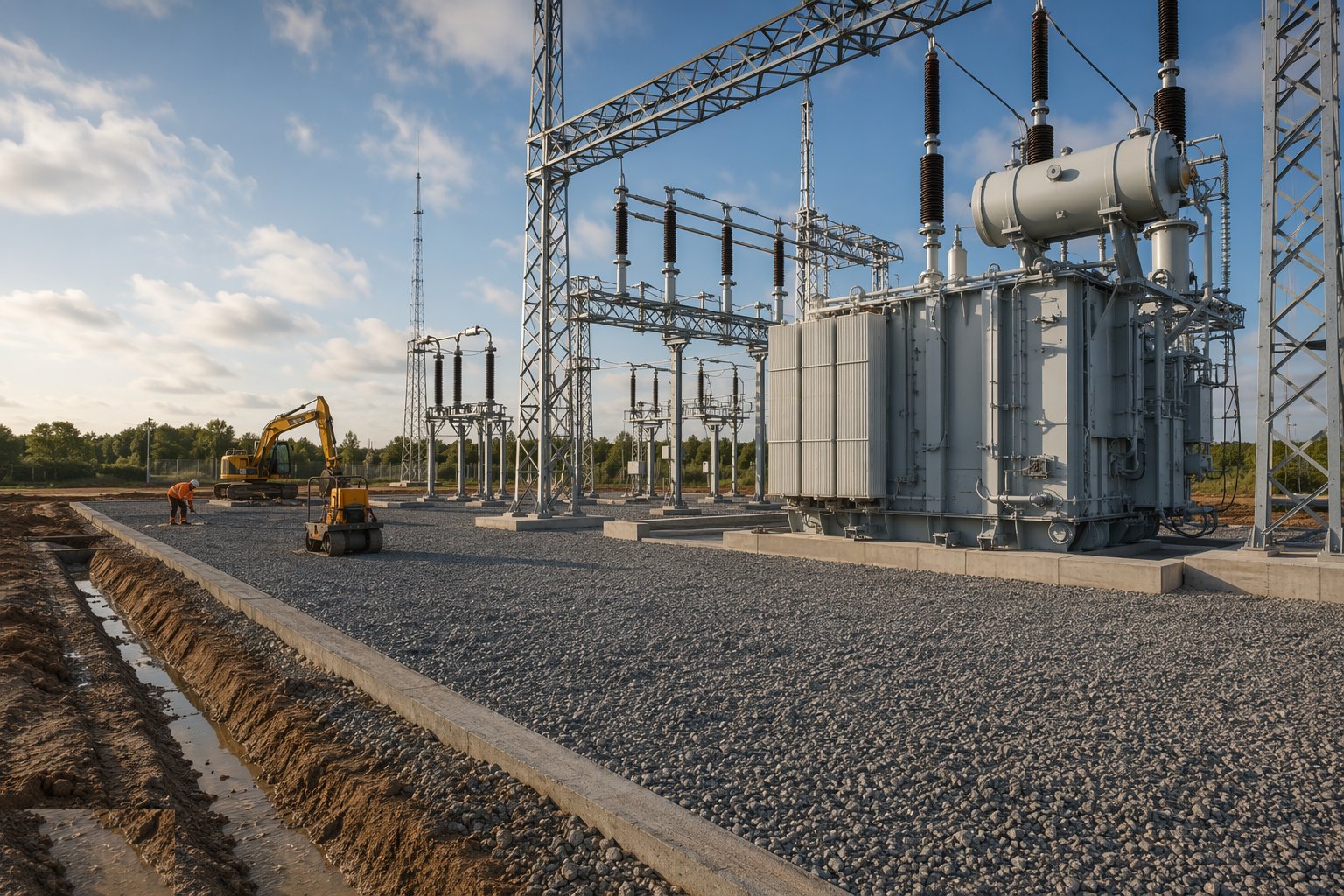
The compound is levelled and terraced to a drained platform — substations hate standing water, and the surface drainage is designed to take rainwater away from plant and to route any oil-contaminated run-off through the bund system, not into the ground. Access for abnormal loads is confirmed from the public road to the transformer plinth — the heaviest load of the whole job arrives once, and the route, the ground bearing and the turning geometry are proven before the civils close in. Perimeter fencing, security and the access control regime follow, because a substation is a dangerous place that children and copper thieves both find attractive.
Step 2: Install the earthing grid before anything is buried
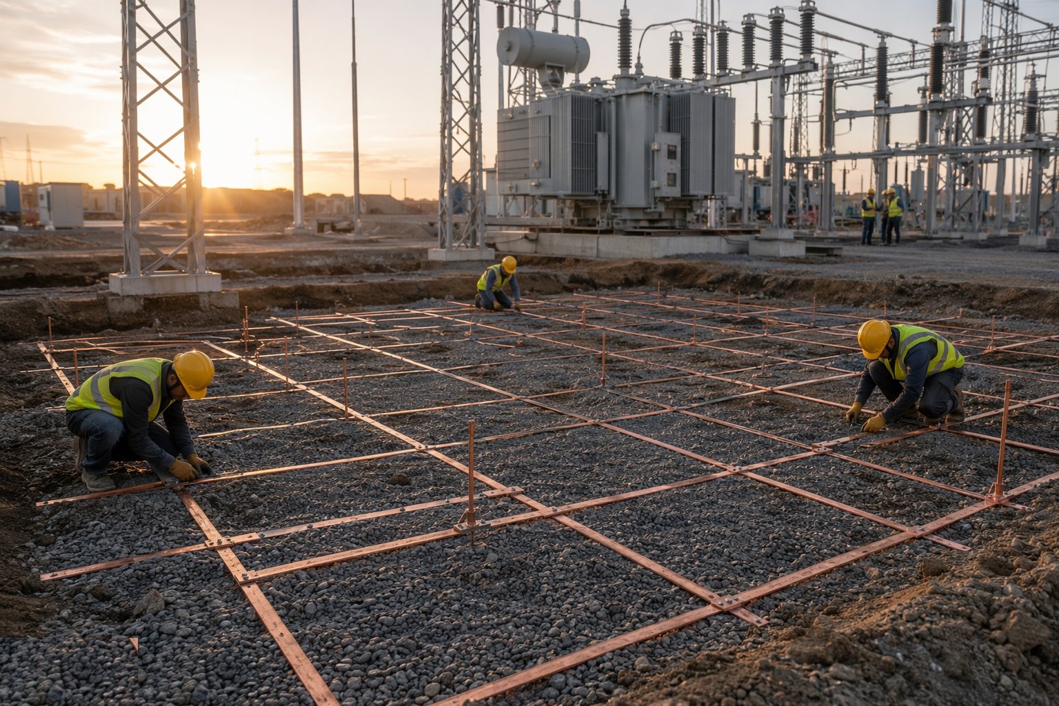
The earth grid goes down first, across the entire compound footprint: copper tape or stranded conductor on its designed grid spacing, joints brazed or exothermically welded — never just clamped and forgotten — earth rods driven at the perimeter and bonded in, and connections raised for every future plinth, gantry leg and fence. Every joint is inspected, photographed and recorded on the grid drawing before backfill, and the grid resistance is tested against the design value to BS EN 50522 and the ENA technical specification. This mesh is the thing that keeps a fault survivable; it is also the thing that will never be accessible again. Treat both facts with equal respect.
Step 3: Cast plinths, bunds, trenches and building foundations
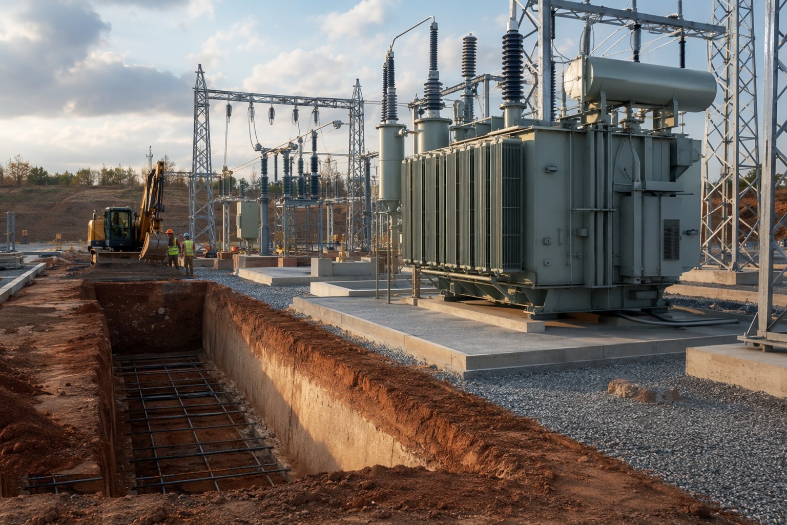
Foundations follow the grid: transformer plinths cast with their rails embedded to level — a transformer that will not roll true on its rails is a heavy-lift problem with a permanent address — bunds sized for the full oil volume with their drainage and oil separation, and plinths for breakers, disconnectors and instrument transformers set to the levels the erection drawings assume. The cable trench network is cast with falls to sumps, covers, and segregated routes for HV, LV and multicore control cables. The control and protection building goes up on its foundations — blockwork and render in the Gulf, block or steel-framed in the UK — with cable entries, fire stopping and the blast/fire separation details the design demands between oil-filled plant and occupied rooms.
Step 4: Deliver and install the transformers
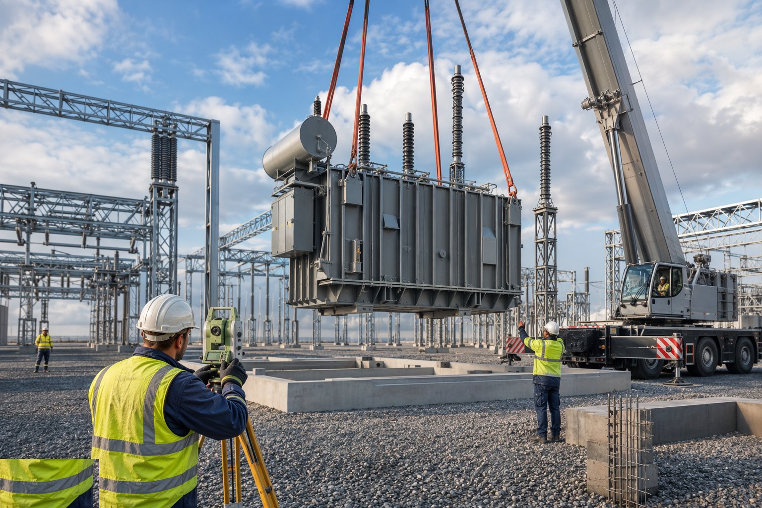
The transformer arrives as an abnormal load — route surveyed, bridges assessed, police or authority notifications done — and is offloaded by jacking and skating or by heavy crane onto its plinth, pushed to its final position on the rails and locked. Dressing follows: radiators lifted and bolted, bushings fitted under covers with moisture discipline — the core sees air only as long as the procedure allows — conservator and breather mounted, and the unit oil-filled or topped up under vacuum per the manufacturer's procedure, with oil samples taken for dissolved gas analysis before and after. Nothing about this step is rushed; a transformer is a 40-year asset with a two-day installation window, and the paperwork — delivery impact recorder readings, oil test certificates, the dressing log — is part of the asset.
Step 5: Erect the switchgear and make the HV connections
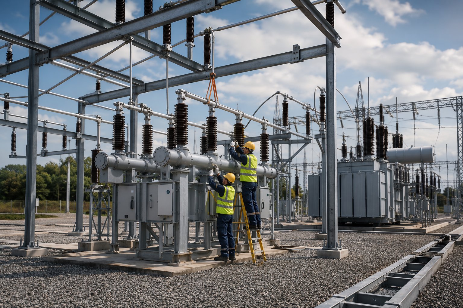
AIS switchgear is erected bay by bay: support steel bolted and torqued, breaker and disconnector mechanisms lifted onto plinths, aligned and anchored, busbar clamps and connectors made off and torqued to specification — HV bolted joints carry hundreds of amps, and an under-torqued joint is a hot spot waiting for its infrared portrait. GIS modules are landed inside their building in clean conditions, jointed with the gas system evacuated and filled to pressure, every compartment's gas density monitored from day one. Gantries are erected, strung busbars tensioned and sagged, and the station earth connections bonded from every item of plant back to the grid laid in step two.
Step 6: Install control, protection and SCADA systems
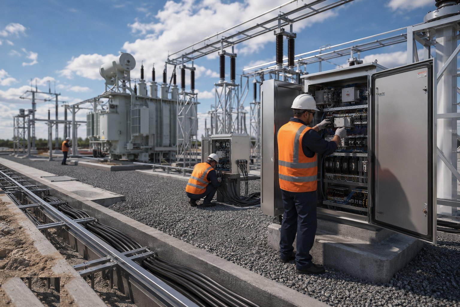
The control building fills with the secondary systems: protection relays and control panels, the DC battery system that keeps protection alive when the AC dies, multicore cabling pulled through the trenches from every bay, terminated core by core to the schedules, and SCADA and telecontrol outstations connecting the site to the network operator's control room. Every core is rung out and identified, CT and VT ratios and polarities are proven, and trip circuits are tested from relay to breaker — because a protection system that has never tripped its own breaker on test has never been tested at all. This is the patient end of the job: terminations by the thousand, each one documented.
Step 7: Pre-commission and prepare for energisation
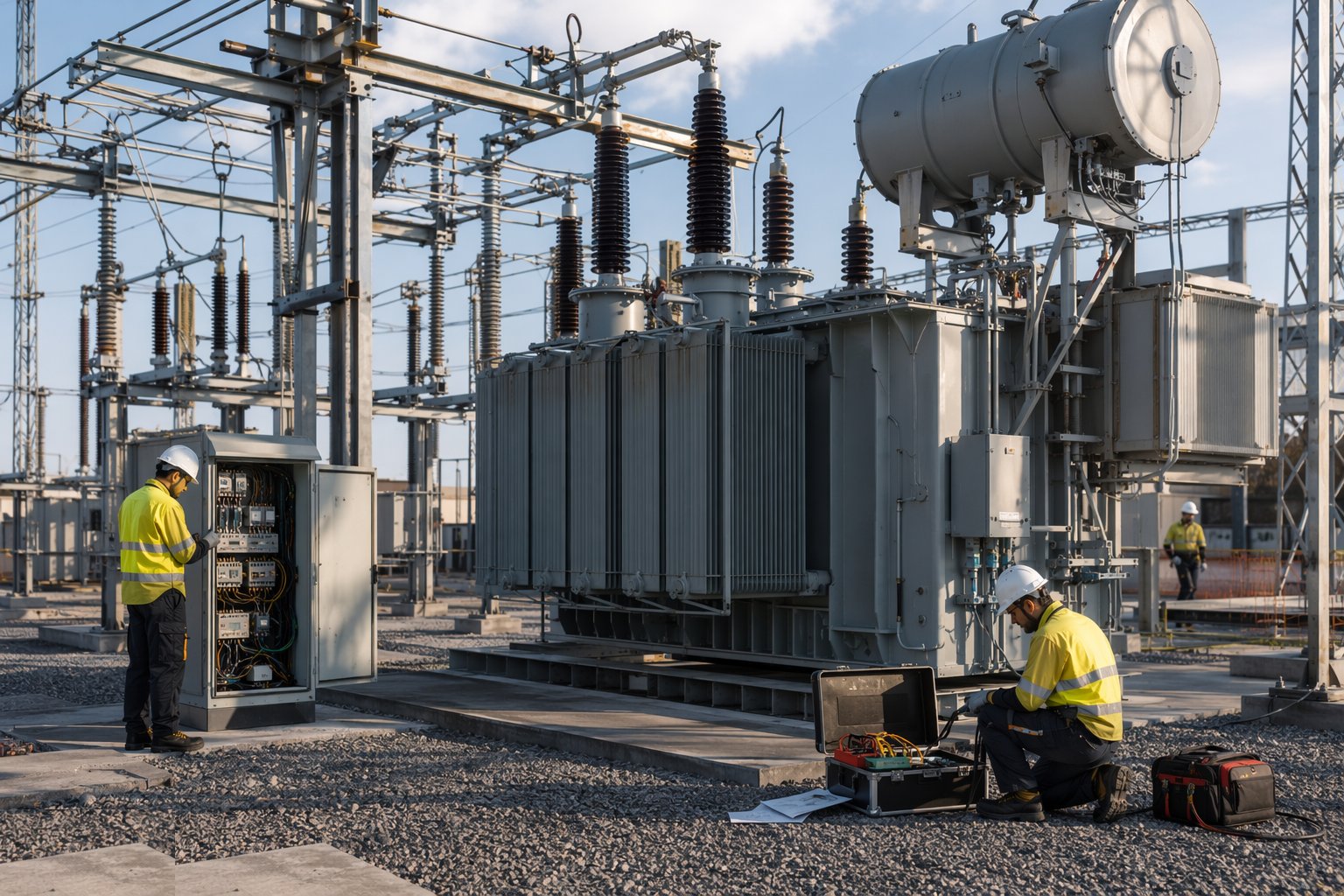
Before any voltage arrives, the site runs its pre-commissioning programme: breaker timing and contact resistance tests, CT and VT injection tests, transformer insulation and oil tests with dissolved gas analysis, gas quality checks on GIS, point-to-point SCADA verification with the control room, and the earthing and bonding re-proven. Punch items are closed, the compound is finished — stone surfacing, fencing complete, signage and danger plates to the operator's standard — and the handover file is assembled: test certificates, settings records, as-builts, O&M documentation. The substation then sits ready, and the energisation itself belongs to the grid connections process: permits, switching programmes and the network operator's authorised staff taking over the keys.
Plant and equipment
- Heavy-haulage and self-propelled modular transporters for transformer delivery; jacking and skating gear
- Crawler and mobile cranes for transformer dressing, GIS modules, gantries and switchgear
- Exothermic welding and brazing kits for the earth grid; earth resistance test equipment
- Concrete plant and formwork for plinths, bunds and trenches; rail-setting jigs
- Torque-controlled bolting equipment for HV connections and structural steel
- Vacuum oil-processing and filtration units; oil sampling and DGA test arrangements
- SF6 handling, evacuation and filling equipment with gas analysers for GIS
- Secondary injection test sets, breaker analysers and SCADA test kit for pre-commissioning
Quality control checks
- Earth grid: every joint inspected and recorded before backfill; grid resistance tested against the design to BS EN 50522 / ENA technical specifications
- Transformer plinth rail levels and alignment surveyed before delivery; bund capacity verified against oil volume
- Transformer delivery records — impact recorder, oil and DGA certificates, dressing and vacuum-fill logs
- HV connection torque records and contact resistance tests on bolted joints
- CT/VT ratio and polarity tests, trip checks relay-to-breaker, and SCADA point-to-point schedules signed off
- GIS gas handling records: evacuation, fill pressures, dew point and leakage checks per compartment
Safety considerations
- Adjacent live circuits: in existing compounds everything not proven dead is live — the operator's safety rules, permits and authorised staff govern every task
- Heavy lifts and abnormal loads: transformer handling planned to the tonne, with banksmen, exclusion zones and proven ground bearing
- SF6 gas: an asphyxiant that pools in trenches and pits — ventilation, monitoring and gas-handling discipline on GIS work
- Stored energy: charged batteries, spring-charged mechanisms and capacitors all bite after isolation
- Work at height on gantries and busbar structures — harnesses, MEWPs and falling-object control
- Transformer oil: fire risk during hot work and spill control during filling, with the bund system live from day one
Common defects
- Earth grid joints clamped rather than welded, or unrecorded — the buried defect found only by a failed resistance test
- Plinth rails or levels out of tolerance — transformers that will not set down true and breakers bolted to shims
- Cable trenches falling the wrong way or unsealed — ponded water around multicores and fire-stopping gaps into the control building
- Under-torqued HV connections — hot joints found by thermal survey after energisation, at outage prices
- CT or VT wiring errors and wrong ratios — protection that mal-operates on first fault instead of clearing it
- Bund capacity short or oil drainage blocked — a leak becoming a pollution incident instead of a contained one
Best suited for
- New load connections: city districts, industrial campuses, data centres needing dedicated grid injection
- AIS compounds where land is available and maintainability in the open air wins
- GIS installations in urban and land-constrained sites, including indoor and basement substations
- Standardised distribution substation programmes rolled out to a repeating design
How long does Substation Construction take?
Typical duration: A distribution substation takes 6–12 months from civils start to energisation readiness; a transmission AIS or GIS grid substation runs 18–30 months, with transformer and switchgear lead times — not the civils — usually setting the critical path..