Overhead Line Construction
Lattice towers and steel poles marching across country — four foundations per tower, steel stacked in sections, and conductors strung under tonnes of tension and sagged to the millimetre.
Last updated 2026-07-28 by the BuildPedia Editorial Team.
What is Overhead Line Construction?
An overhead line is structure, not equipment: towers carrying conductors through the air on insulators, at clearances the design codes dictate, from substation to substation across whatever the route contains. UK transmission runs on lattice steel towers — the standard double-circuit families that have carried the 400 kV supergrid since the 1960s, with newer low-height designs and the T-pylon joining them on recent routes — while distribution at 33 kV and below rides on steel poles, and the lowest voltages still hang on wood poles in country districts. In the Gulf the same grammar applies at larger scale: lattice towers on 400 kV and 132 kV corridors crossing sabkha and dune, engineered for heat that sags conductors further than any UK summer will. Every tower stands on four foundations — one per leg — and the line's whole geometry, its clearances and its safety, flows from four concrete blocks in the ground being in exactly the right place.
The standard foundation is the pad and chimney: a mass concrete pad at depth taking the uplift and bearing, a concrete chimney rising to ground level, and the tower's stub angle cast in, set to line, level and batter with a template jig — because the leg bolts to that stub, and a stub set wrong means packers, cut steel, or a redesigned leg. Poor ground — peat, soft alluvium, sabkha — changes the answer to piles, rock anchors, or grillage bases, and every foundation design follows the ground investigation because a tower in service sees wind uplift on two legs and compression on two, cycling with every storm. Towers go up section by section: built on the ground and crane-lifted in lifts where access allows, or erected piecemeal with a derrick or gin pole where it does not, every bolt torqued and every member checked against the erection drawings as it rises.
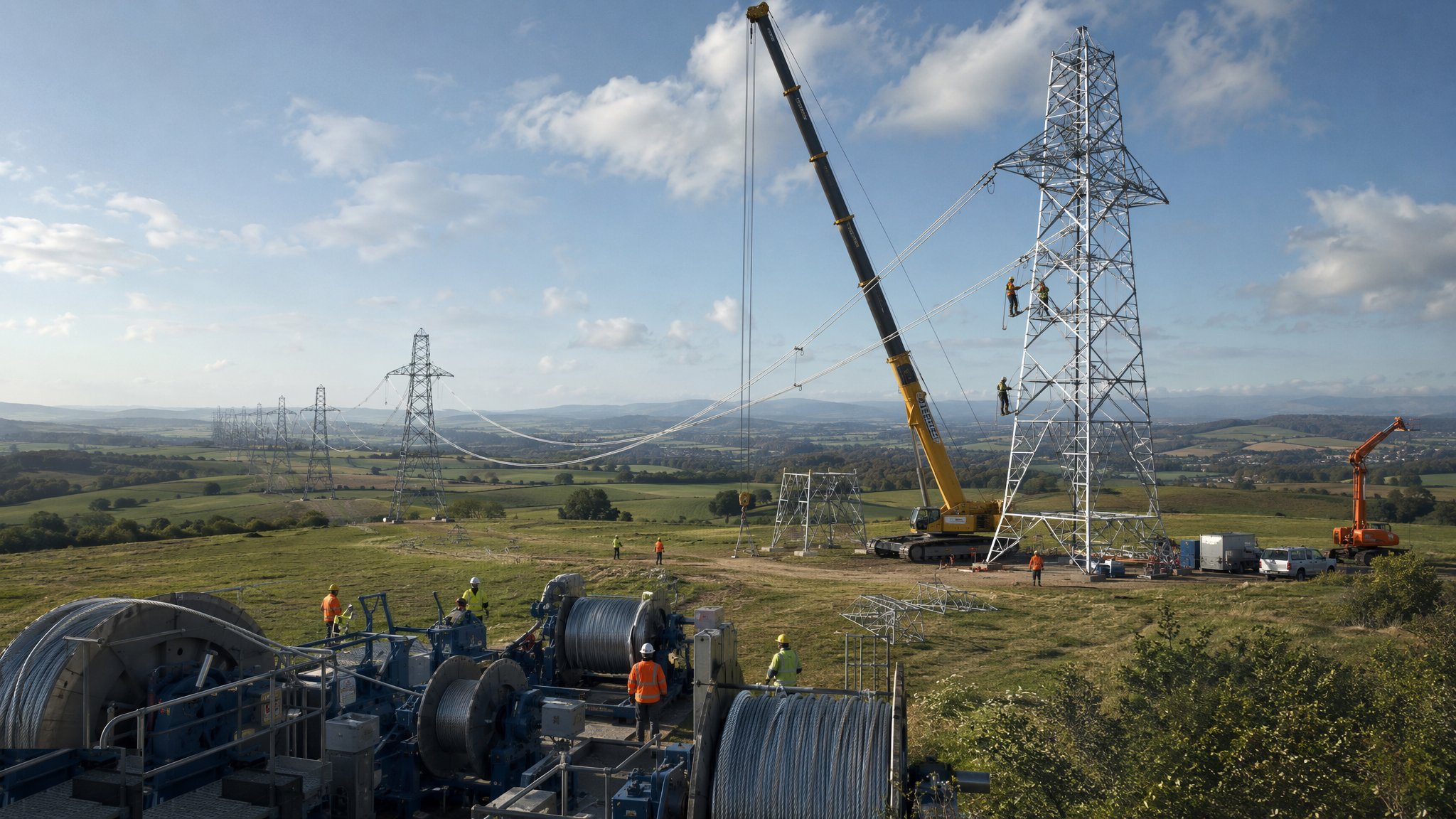
Then comes the part that looks like magic and is actually tension management. Conductors — aluminium strands over a steel core, or all-aluminium alloy on distribution — are strung using pilot lines pulled through running blocks on each tower, followed by the conductor itself pulled by a winch at one end and held back by a tensioner at the other, so it never touches ground, trees, roads or live circuits it crosses. Each section is then sagged: pulled to a tension read from the sag-tension charts for the span, the temperature and the conductor's creep behaviour, marked, and clipped into the insulator clamps — with vibration dampers and spacers fitted on bundled conductors, because a conductor left free to gallop and vibrate fatigues its own strands at the clamps. Sagging is where the design meets the weather: too slack and clearances fail in summer; too tight and ice and wind load the towers beyond their design. The line is finally earbonded, earthed through counterpoise or earth wires, and inspected end to end before it is handed to the energisation team.
When and why is Overhead Line Construction used?
Overhead lines are built to connect generation, reinforce the grid, or feed load where burying cable would cost five to ten times as much — which is most of rural and semi-rural country. They matter because they are the grid's long-distance haulage: a double-circuit 400 kV line carries the output of a power station across counties, and its availability is a national number, not a project one. For the builder, the defining conditions are access and weather: the route crosses farmland, moor, forestry and water, with temporary accesses to every tower position, stringing sections planned around roads, rivers, railways and live circuits, and erection and sagging limited by wind. The work is spread over kilometres with a hundred landowners, so the programme lives or dies on logistics — and on the discipline that treats a tower foundation in a wet field with the same survey rigour as one beside a motorway.
Types of Overhead Line Construction
Lattice steel tower lines
The transmission standard: four-legged galvanised steel towers in suspension, tension and terminal variants, carrying one or two circuits. Proven, repairable, climbable, and spanning rivers and valleys on special crossings — at the cost of a footprint, a visual presence, and four foundations per tower.
Steel pole and compact lines
Single steel poles or narrow portal structures for 33–132 kV, and compact low-height designs — the T-pylon family being the UK's recent answer — where visual impact or wayleaves argue against lattice towers. Faster to erect with fewer foundations, but tighter working clearances and heavier single lifts.
Wood pole distribution lines
The 11 kV and LV countryside network: creosoted or treated poles, pole-mounted transformers, stays and struts, worked from MEWPs and pole climbs. The craft end of the trade — small structures, live-rural access, and lines that have to survive storms for forty years on a single buried butt.
Reconductoring and refurbishment
Not new build but a huge share of the work: old conductors and fittings stripped and replaced on standing towers, foundations upgraded, steel members changed out — often with one circuit live beside the work. The same stringing skills under the network operator's permits, with induction from the live circuit as the constant companion.
Overhead Line Construction: step by step
Step 1: Survey the route, plan access and spot the towers
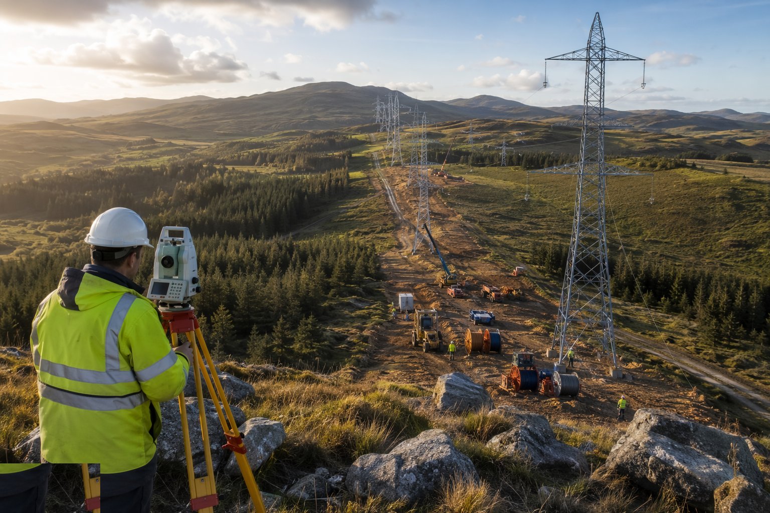
The line route is surveyed end to end — profiles, crossings, ground conditions — and every tower position is spotted: set out from the design line, checked for clearance to obstacles, and adjusted within the spotting rules before foundations are committed. Temporary access is built to each position, which on a rural line is a project in its own right: stone tracks across farmland, bog mats across peat, river and road crossing plans, and reinstatement promises to a hundred landowners. Ground investigation at each tower tells the foundation designer what the pad and chimney must sit in — and finding running sand or peat after the excavation is open is how programmes drown.
Step 2: Construct the foundations
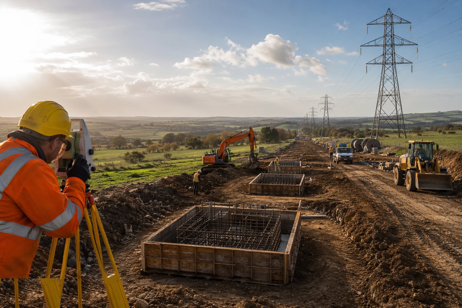
Four foundations per tower: excavated to the design depth, the pad cast, the chimney formed above it, and the stub angle set in the fresh concrete with a rigid template holding line, level, batter and diagonal — then left undisturbed until the concrete has strength, because a stub knocked out of position by a careless boot or bucket is baked into the structure. Backfill goes on in compacted layers around the chimney; in uplift ground the backfill is part of the foundation's resistance and its compaction is a specified, inspected activity, not a tidy-up. Piled or anchored foundations follow their own procedures in poor ground. The stub survey closes each foundation: positions, levels and diagonals recorded against tolerance before the steel arrives.
Step 3: Erect the towers
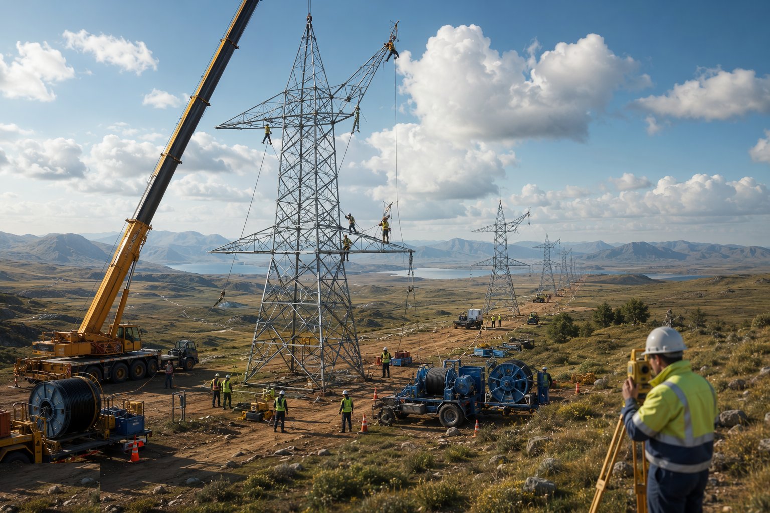
Steelwork is erected in lifts where crane access allows — body sections assembled on the ground, lifted, bolted and torqued as the tower grows — or piecemeal with a derrick where the ground says no crane. Members are sorted and checked against the erection drawings before lifting; every bolt is torqued and marked, and nothing is left finger-tight overnight because a tower relying on half-torqued bolts in an overnight gale is a bent tower by morning. Alignment is checked as the tower rises — a leg out of plumb at twenty metres is a cross-arm out of position at forty — and the completed tower is torque-audited and surveyed before stringing loads ever reach it.
Step 4: Fit insulators, hardware and earthing
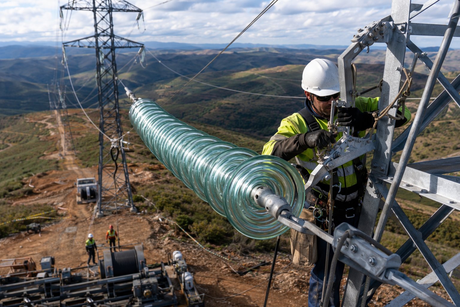
Before a conductor moves, the towers are dressed: insulator strings — cap-and-pin glass or porcelain, or composite long-rods — hung at each suspension and tension position, arcing horns and fittings assembled, running blocks hung for stringing, and the tower earthing installed with its counterpoise or earth wire connections. Insulators are handled like the fragile, safety-critical components they are — a chipped disc or a kinked composite shed is scrapped, not straightened — and every fitting is checked against the hardware schedule, because the difference between a suspension and a tension clamp matters at 400 kV.
Step 5: Run out the conductors
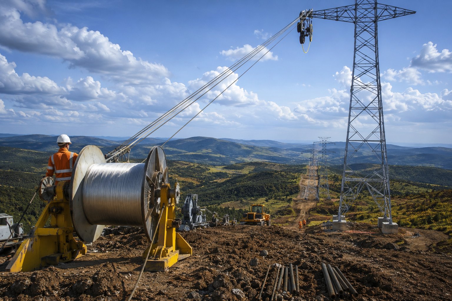
Stringing starts with the pilot: a light line pulled through every running block along the section — by ground crew, and increasingly by drone over crossings — then the draw rope, then the conductor itself, paid off the drum through a tensioner that holds back tension the whole way so the conductor travels clear of the ground and everything beneath it. Crossings of roads, railways, rivers and live circuits are planned events with their own method statements, scaffolds, nets or outages. The pulling tension is logged continuously; a snag on the line — a jammed block, a grounded conductor — shows as a spike, and you stop and find it, because a conductor dragged over a stone has broken strands where you cannot see them.
Step 6: Sag, clip in and fit dampers and spacers
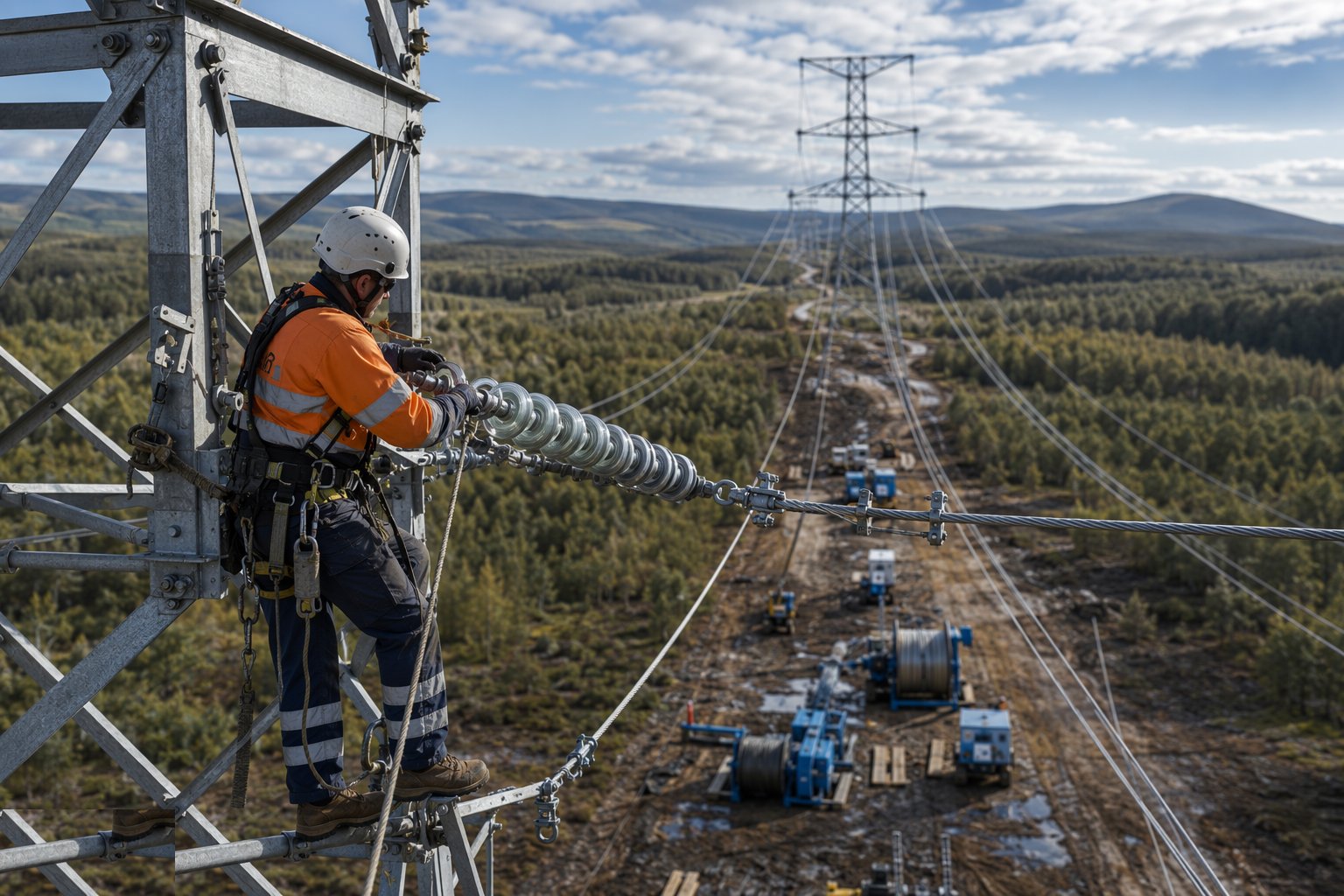
Each section is sagged to the charts: tension applied to the calculated value for span and temperature, checked by dynamometer or sag scope against the sag boards set in the spans, adjusted for creep where the charts demand, then clamped and clipped into the insulator hardware span by span. Vibration dampers go on at their measured distances from the clamps, spacers and spacer-dampers are installed along bundled conductors at their design spacing, and jumper connections are formed at tension towers. This is the step the line's whole life depends on: sag wrong and clearances or tower loads fail years later, dampers missing and the conductor fatigues at the clamps — invisible until the strand count comes back from the failure investigation.
Step 7: Test, inspect and hand over for energisation
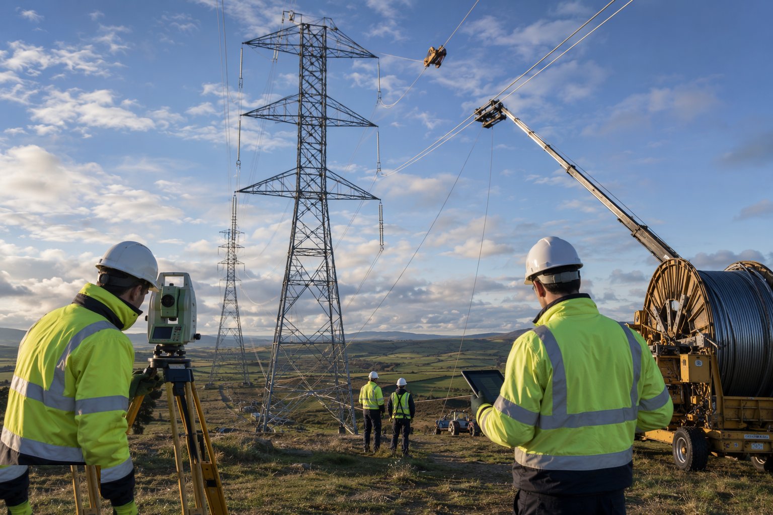
The finished section is proven before voltage: conductor continuity and phase identification checked end to end, earth continuity and footing resistances measured, clearances surveyed at crossings, and the line walked or flown for a final inspection — every pin, every damper, every clipped conductor. The as-built file assembles the foundation surveys, torque records, stringing tension logs and sag records per section. Then the line is handed to the network operator's authorised staff for the energisation process — permits, point-on-wave or straight switching, and the first voltage — and the construction team's kilometres of countryside become a line on the grid control room's wall diagram.
Plant and equipment
- Excavators and mobile batching or ready-mixed supply for foundations; stub-setting templates and jigs
- Cranes for section erection; derricks, gin poles and winches where crane access is impossible
- Torque wrenches and audit equipment for the thousands of structural bolts
- Stringing equipment: pullers, tensioners, drum stands, running blocks and pilot-line systems (including drones)
- Dynamometers, sag scopes and sag boards for tensioning and sagging
- MEWPs and climbing equipment for fitting-off and inspection
- Conductor jointing and compression equipment — hydraulic presses for mid-span joints and dead-ends
- Earth test instruments and footing resistance test kit
Quality control checks
- Stub angle surveys per foundation: line, level, batter and diagonals recorded before backfill and again before steel
- Foundation concrete cube records and backfill compaction where uplift depends on it
- Bolt torque records and audits per tower section; missing-member and missing-bolt check before stringing
- Stringing tension logs continuous per pull; conductor inspection for damage at drums and blocks
- Sag records per section against the sag-tension charts; damper and spacer positions measured per span
- Electrical tests before energisation: continuity, phase identification, earth and footing resistance, clearance surveys
Safety considerations
- Work at height: tower climbing with fall-arrest discipline, MEWPs where terrain allows, rescue plans for climber incapacity
- Conductors under tension: tonnes of stored energy — snap-back kills; stand clear of the bight, guard the pulling line, respect the breaking strain
- Induced voltage from parallel live circuits: conductors and equipment bonded and earthed at every work site — induction has killed men on dead lines
- Dropped objects from towers: exclusion zones below erection and fitting-off, tool lanyards, bolt discipline
- Weather limits: wind stops lifts and stringing; lightning stops everything on an exposed ridge
- Public interface at crossings: roads, footpaths and railways protected during stringing — a dropped conductor on a live motorway is not an option
Common defects
- Stub angles set wrong — towers erected on packers and bent legs, or legs redesigned at fabrication prices
- Missing or under-torqued tower bolts found at audit — or found by the wind
- Wrong sag: conductors too tight loading towers beyond design in ice and wind, or too slack failing clearances in summer
- Damaged conductor strands from snags, bad blocks or rough handling — fatigue failures at clamps years later
- Dampers and spacers missing or misplaced — aeolian vibration eating the conductor at the clamps
- Poor tower earthing: counterpoise omitted or corroded, footing resistances high, and lightning performance to match
Best suited for
- Long-distance transmission where overhead costs a fraction of underground cable
- Rural and semi-rural routes with wayleaves available and crossings manageable
- Grid reinforcement by reconductoring existing routes to higher-capacity conductors
- Distribution in open country where poles and access are straightforward
How long does Overhead Line Construction take?
Typical duration: Foundations run one to two weeks per tower including cure, erection two to five days per tower with good access, and stringing progresses in multi-kilometre sections — a 20 km double-circuit transmission line typically takes 18 to 30 months end to end, weather and wayleaves permitting..