Research Campus Infrastructure
The utilities, energy and ground engineering that let a science campus run: resilient power and cooling, gas farms, vibration-isolated slabs and buildings handed over in phases while research carries on next door.
Last updated 2026-07-28 by the BuildPedia Editorial Team.
What is Research Campus Infrastructure?
A research campus lives or dies on its infrastructure, and the infrastructure is sized by paranoia. An office block loses power and everyone goes home; a research building loses power and a decade of cell lines, a cryostat chain or a beamline experiment dies with it. Campus energy is therefore designed for resilience: dual utility feeds or ring supplies, N+1 standby generation, UPS on the critical boards, chilled water and often district energy or CHP at campus scale, with landlord plant sized for the tenant fit-outs to come. The distribution is campus-scale civil engineering — buried HV rings, thermal networks in accessible ducts or tunnels, and utility corridors reserved so the campus can grow without digging up its own spine road every five years.
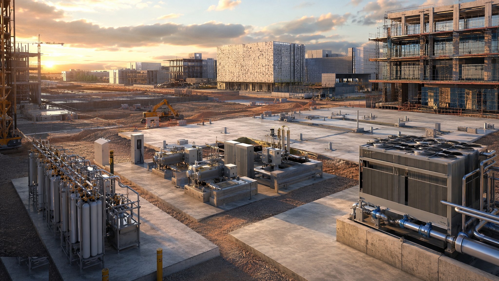
Then the specialist provision no ordinary business park carries. Gas farms and stores: bulk liquid nitrogen tanks on concrete plinths with oxygen depletion monitoring downstream, cylinder stores for hydrogen and specialty gases with the separation distances, fire rating and ventilation the dangerous substances regime demands, and piped distribution into the buildings. Chemical and solvent stores with bunding and fire separation. And under the instrument buildings, the ground engineering: vibration-isolated slabs — thick, stiff ground-bearing rafts or inertia masses on isolation bearings, detailed so the service yard traffic, the cooling tower and the piling rig two plots away never reach the electron microscope suite at better than its VC criterion.
The fourth dimension is phasing. Research campuses are rarely built in one go, and they are almost never empty while they grow: plots are serviced and released building by building, occupied laboratories run next to live construction, and the infrastructure has to be delivered in self-sufficient phases — each with power, water, drainage and access that work on day one and still work when phase three ties in. Vibration, dust, noise and services outages are controlled at the boundary between construction and occupation like a hospital project, because a wrongly timed power outage or a weekend of uncontrolled piling vibration can destroy experiments the way a fire would.
When and why is Research Campus Infrastructure used?
Campus infrastructure applies to science parks, university research quarters, pharmaceutical campuses and innovation districts — anywhere multiple specialist buildings share utilities, energy and ground. It runs ahead of and alongside the buildings: enabling infrastructure first, plot-by-plot servicing as buildings proceed, and reinforcement phases as the campus fills. It earns its keep because the specialist demands are cheapest bought once: a resilient campus energy centre is a fraction of the cost of every tenant installing their own standby plant, and a vibration-quiet zone is only possible if the heavy infrastructure — roads, plant yards, substations — is deliberately placed away from it at masterplan stage. Get the infrastructure wrong and every subsequent building pays a tax: oversized individual plant, compromised instrument rooms, or a campus that cannot attract the tenants it was built for.
Types of Research Campus Infrastructure
Campus energy centres and thermal networks
Centralised CHP, boilers and chillers — often with district cooling in the Gulf — distributing heating and chilled water through buried pre-insulated pipework or accessible tunnels, with N+1 plant and building-by-building connections. Efficiency and resilience bought once, at campus scale.
Resilient electrical infrastructure
Dual-fed or ring HV networks, campus substations, standby generation and UPS architecture sized for research loads, with critical/non-critical segregation carried through to the buildings. Designed so a single fault — or a planned outage — never reaches a live experiment.
Specialist gas and chemical infrastructure
Bulk liquid nitrogen and cryogenic stores, hydrogen and specialty gas cylinder compounds, piped distribution, and bunded chemical stores — engineered for separation distances, ventilation, fire rating and monitoring under the dangerous substances and pressure systems regimes.
Vibration-controlled development zones
Masterplanned quiet zones: heavy plant, roads and logistics kept remote, instrument buildings on vibration-isolated slabs or inertia bases, and construction logistics managed so the operating campus never exceeds its vibration budget.
Research Campus Infrastructure: step by step
Step 1: Masterplan the utility corridors and quiet zones
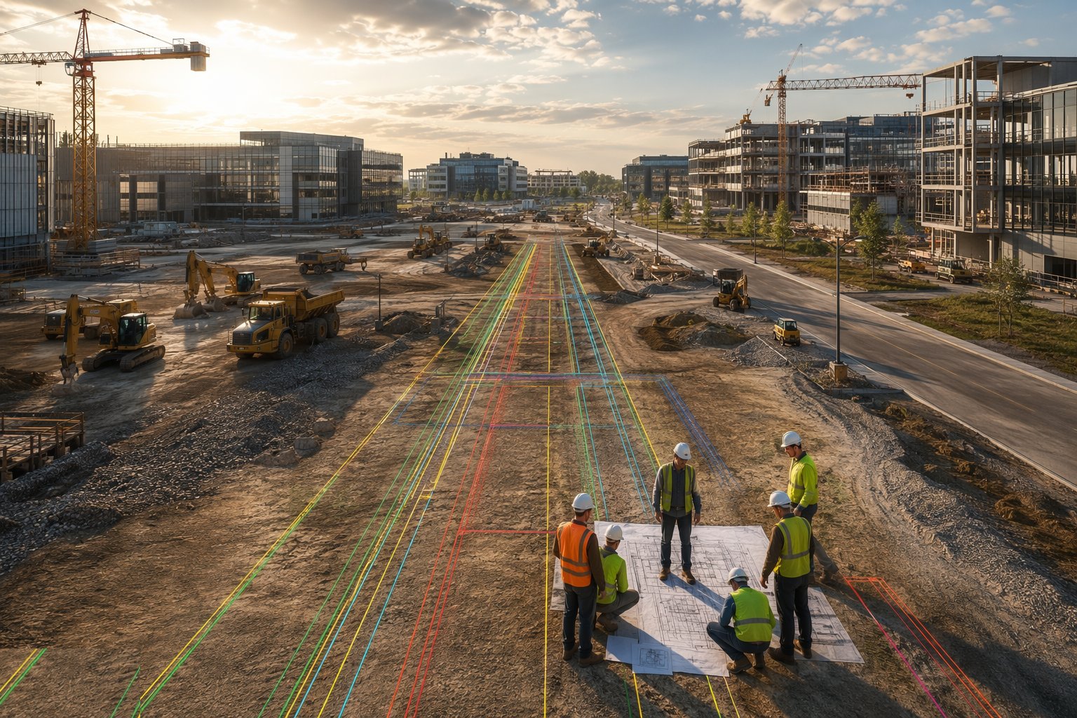
Before a trench is dug, the campus map is fixed: utility corridors with reserved widths for HV, thermal, water, gas and data — including future capacity, because retrofitting a corridor through an occupied campus is excavation hell — and the vibration zoning that keeps substations, energy centres, yards and haul routes remote from the instrument plots. Diversion or reinforcement of existing utilities is settled with the network operators early; campus-scale loads mean long-lead conversations about firm capacity, and the client who assumes the local network has 20 MVA spare learns otherwise at the worst moment.
Step 2: Install primary distribution: HV, thermal and water
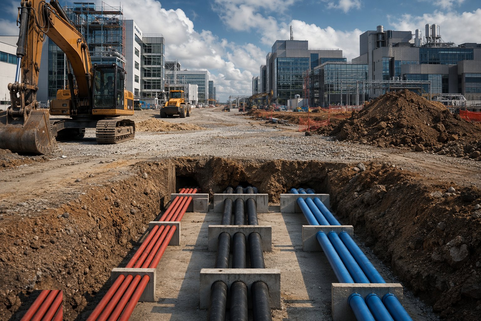
The buried arteries go in phase by phase: HV ring circuits in ducts with draw pits at building plots, pre-insulated heating and chilled water mains laid to falls with expansion and anchor details engineered, water and drainage mains sized for the full build-out. Where tunnels or accessible ducts are used, they are built for a century of opening — drainage, lighting, access points and space for the next pipe. Every phase terminates in a self-sufficient condition: capped, valved and energisable so plot release never waits for phase three.
Step 3: Build the energy centre and resilience plant
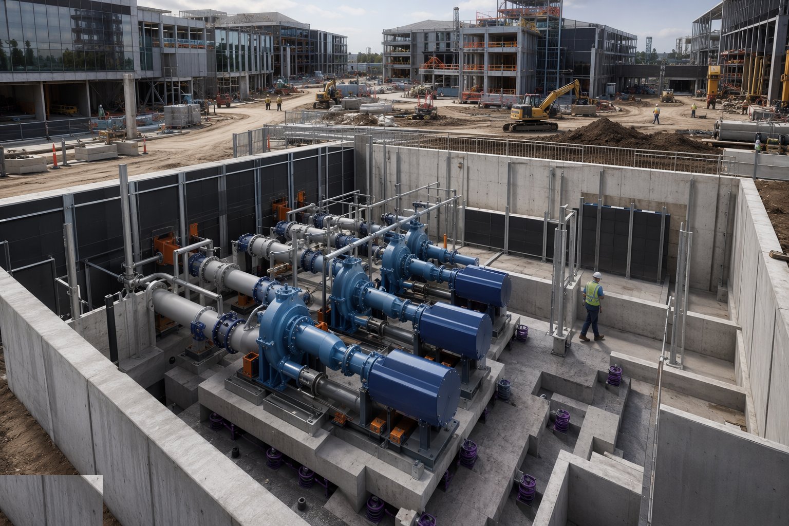
The energy centre rises with its heavy kit landed on inertia bases: CHP engines, boilers, chillers, pumps and the acoustic and vibration isolation that keeps it a good neighbour. Standby generation and UPS plant are installed with their fuel systems and exhaust routes, then the proving begins — black-start tests, load-bank runs, changeover trials that demonstrate the critical boards never see a blip. On a research campus these tests are witnessed like containment commissioning: the resilience is the product.
Step 4: Install gas farms, stores and specialist distribution
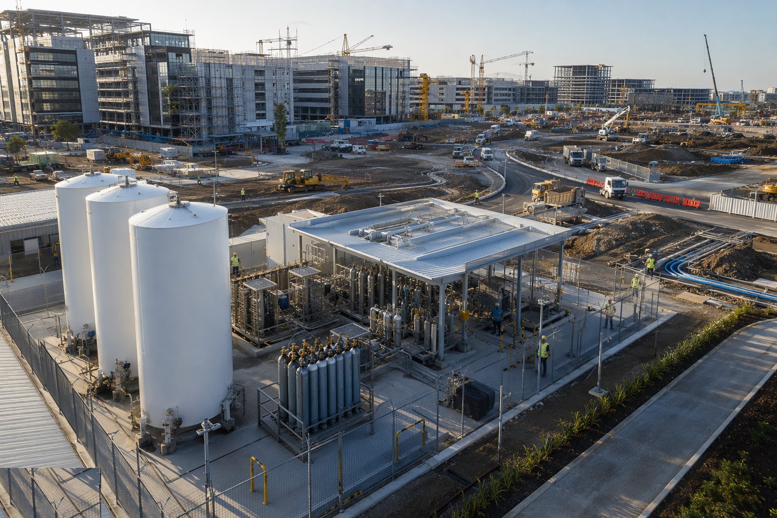
Bulk tanks and cylinder compounds are built to their consented layouts: concrete plinths, separation distances to boundaries and buildings, fire-rated and ventilated stores, crash protection against vehicle impact, and piped distribution in cleaned, tested lines to building entry points. Oxygen depletion and gas detection is wired back to monitored panels before any commissioning gas is introduced, and the pressure systems paperwork — written schemes of examination, certification — is assembled as the systems are built, not chased after.
Step 5: Engineer vibration-isolated building foundations
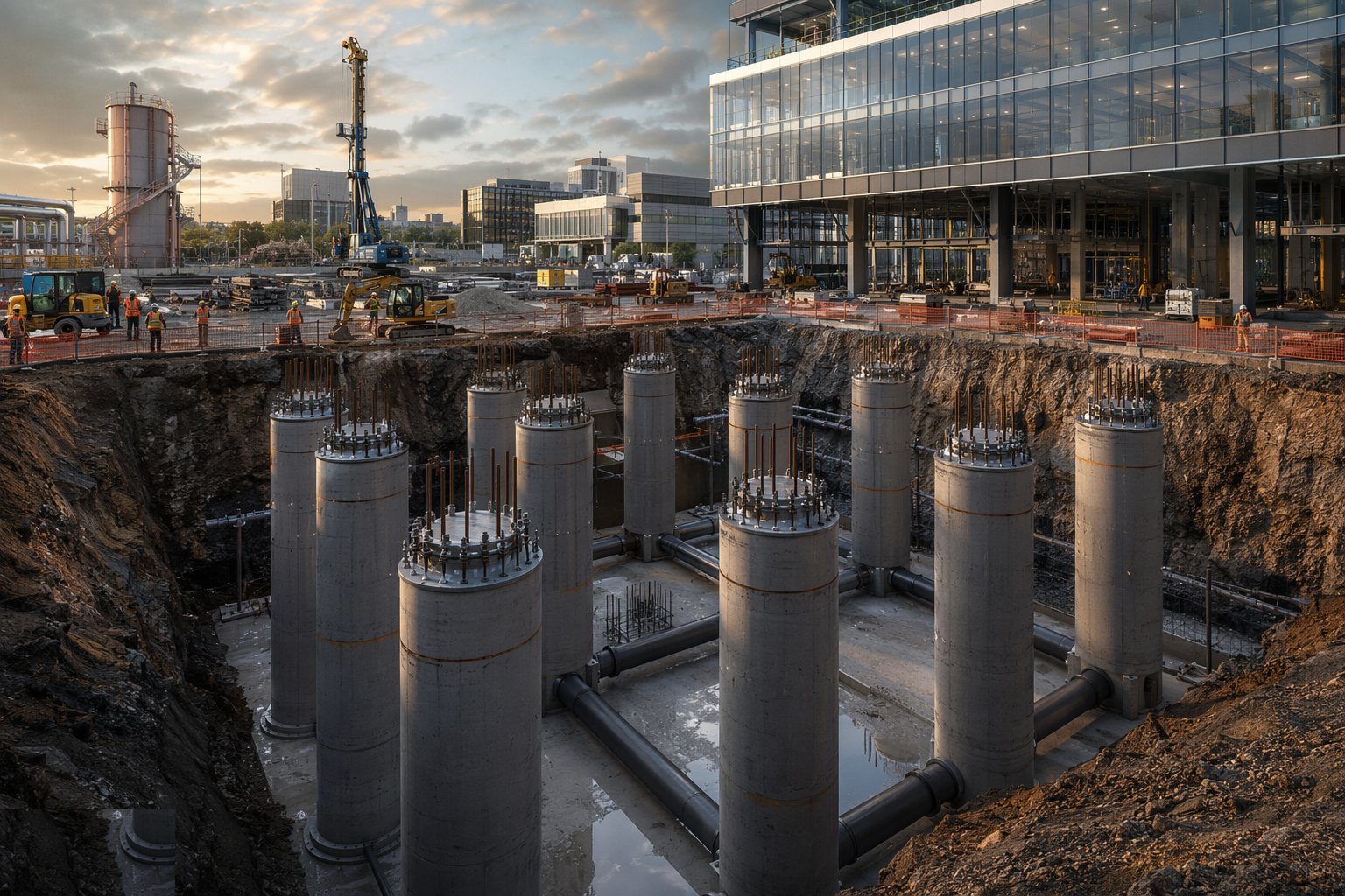
On the instrument plots, the ground engineering delivers the quiet: stiff ground-bearing rafts or inertia blocks on springs or bearings, separated from adjacent structure by isolation joints, with vibration criteria written into the piling, compaction and trafficking method statements for everything built nearby. Baseline vibration surveys are run before construction and the measurement points stay live — when the adjacent plot starts piling, the occupied lab next door has numbers, not opinions, about what reached its floor.
Step 6: Phase plot release and manage the occupied campus
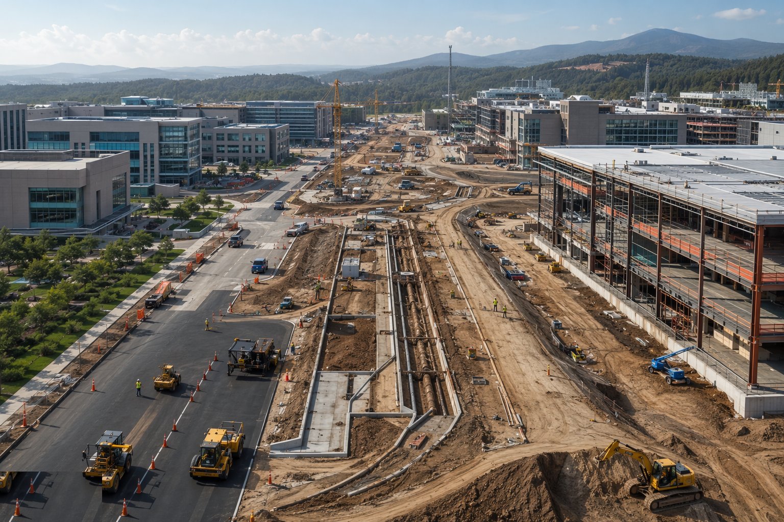
Plot release is a logistics discipline: each serviced plot handed over with power, water, drainage, data and access proven, while construction interfaces with occupation are managed under agreed rules — permitted outage windows, vibration and dust limits, haul routes segregated from campus life. Tie-ins of new phases to live systems are planned like hospital shutdowns: rehearsed, notified, executed in the small hours, and reversed fast if anything misbehaves. The campus that keeps its scientists' trust during the build is the one whose next phase lets easily.
Plant and equipment
- HV switchgear, ring main units and campus substations with dual feeds
- CHP engines, boilers, chillers and pre-insulated thermal network pipework
- Standby generators, UPS systems and load banks for resilience proving
- Bulk cryogenic tanks, cylinder stores, gas detection and piped distribution
- Inertia bases, spring isolators and vibration monitoring instrumentation
- Directional drilling and ducting plant for corridor installation without open cut
- Tunnelling or accessible-duct formwork where utility tunnels are used
- Flow, pressure and energy metering for landlord/tenant utility billing
Quality control checks
- HV jointing and termination records with pressure/sheath test certificates per circuit
- Thermal network weld NDT, pressure test and insulation integrity records per phase
- Black-start, load-bank and changeover test records for the resilience plant, witnessed
- Gas system pressure test and certification; written schemes of examination in place before commissioning
- Baseline and ongoing vibration survey records against the plot VC criteria
- Plot release checklists: every utility proven live and metered at handover
Safety considerations
- HV work under authorisation: switching schedules, permits and sanctioned earthing only
- Cryogenic and gas stores: oxygen depletion monitoring, controlled first-fill procedures
- Deep utility trenches and tunnel works: support, access, confined space controls
- Hot work and fuel systems on standby plant: permits, fire watch and DDA/DCD-equivalent approvals where applicable
- Work adjacent to occupied research buildings: exclusion zones, vibration and dust limits enforced
- Pressure testing of thermal and gas networks: exclusion zones and controlled pressurisation
Common defects
- Utility corridors congested or misplaced, forcing every new plot into road-breaking and diversion chaos
- Resilience that exists on paper: changeover tests skipped, single points of failure discovered by a real outage
- Thermal networks leaking at poorly welded joints or failing insulation — heat loss and groundwater ingress for decades
- Gas stores consented then value-engineered, breaching separation distances and the dangerous substances approval
- Vibration criteria breached by uncontrolled construction on the adjacent plot — complaints backed by the lab's own monitoring
- Phased systems that do not tie in: dead legs, undersized headers and valved-off spurs that never worked
Best suited for
- Science parks, university research quarters and innovation districts
- Pharmaceutical and biotech campuses with shared specialist utilities
- Multi-plot developments where resilience is a tenant attraction
- Campuses combining occupied research buildings with continuing construction
How long does Research Campus Infrastructure take?
Typical duration: Primary campus infrastructure runs 12–24 months for the first phase including energy centre commissioning; plot-by-plot servicing then follows the building programme over years, with each release a 3–6 month package..