Fibre Network Installation
Ducts in the ground, chambers at the corners and hair-thin glass blown between them — the buried network that carries everything, built in live streets and tested to the decibel.
Last updated 2026-07-28 by the BuildPedia Editorial Team.
What is Fibre Network Installation?
The fibre network is a civil engineering project that happens to end in glass. Long before any fibre is blown, the route is built as ducts: typically 40–110 mm polyethylene ducting laid in trenches 300–600 mm deep in footways and carriageways, with jointing chambers at every turn, junction and future breakout point. The duct is the permanent asset — the fibre inside it will be blown, re-blown and upgraded over decades without digging the street again, which is the entire economic argument for doing the civils properly. Chambers range from small footway boxes to deep carriageway jointing chambers with ironwork set in concrete, sized so a splicer can work in them and a drum of cable can be stood beside them.
Getting the duct in the ground is where the programme lives or dies. In the UK, street works run under the New Roads and Street Works Act 1991 — notices to the highway authority, permits on traffic-sensitive streets, traffic management to the Chapter 8 rules, and reinstatement to the Specification for the Reinstatement of Openings in Highways, with the two-year guarantee period hanging over every trench. Open cut is the default in greenfield and footway work; the carriageway alternatives are microtrenching — a narrow saw-cut slot, typically 30–80 mm wide, for microducts, reinstated with flowing grout — and trenchless methods: directional drilling under junctions, railways and anything the highway authority will not let you open. In the Gulf the same ducts go in ahead of development infrastructure, coordinated through municipality and operator (Etisalat (e&) and du) approvals, with the added discipline of deep sand cover, high water tables on coastal routes and summer heat on every trench gang.
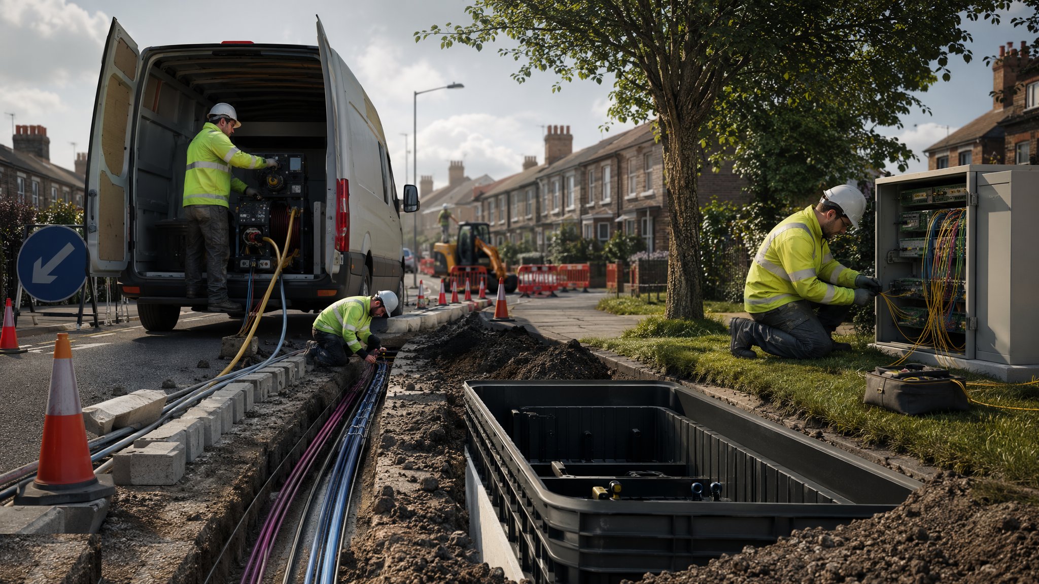
Only when the duct spine is proven does the glass arrive. Fibre cables — anything from a 12-fibre drop to a 864-fibre backbone — are blown with compressed air on a viscous-drag cushion, or pulled where distances are short and bends are few. Every joint is a fusion splice: two fibres stripped, cleaved, aligned and welded in a splicer, protected in a heat-shrink sleeve and organised on a splice tray inside an enclosure. Then the network is proven with light: OTDR traces along every fibre showing every splice loss and the end-to-end attenuation, against a loss budget calculated from the transmission design. A network that cannot produce clean OTDR traces is not a network — it is a very long, very expensive duct.
When and why is Fibre Network Installation used?
Duct and chamber civils run ahead of everything else in a telecoms build because they are slow, permit-bound and weather-exposed, while fibre installation is fast once the route exists. The route method is chosen on what the street will allow: open trench where the highway authority grants road space and the reinstatement liability is acceptable, microtrenching where the carriageway must stay in service and the surface is sound asphalt, directional drilling where an opening is simply forbidden. Chambers go where the network logic demands — bends, branches, building entries — not where digging is convenient, which is why the gang so often excavates in the worst corner of the junction. Skimp on duct depth, chamber quality or reinstatement and the highway authority, the next utility's excavator, or the first HGV over a poorly compacted trench will collect the debt, usually with interest.
Types of Fibre Network Installation
Open-trench duct laying
Conventional excavation in footway or carriageway, ducts bedded and surrounded in sand or specified surround, warning tape above, chambers at design points. The default method: cheap per metre, universally understood, and entirely at the mercy of traffic management, other utilities' plant and reinstatement quality.
Microtrenching
A rock-saw cuts a narrow slot — 30–80 mm wide, up to around 300–400 mm deep — in the carriageway, microduct bundles are placed in the slot, and it is backfilled with a flowing grout or cold-lay reinstatement. Fast and minimally disruptive on sound asphalt, but banned or restricted by some highway authorities, and hopeless where the road is already patched to death.
Directional drilling and thrust boring
Trenchless installation beneath junctions, railways, watercourses and protected surfaces: a guided pilot bore followed by reaming and duct pullback. The answer when digging is refused, at the price of specialist plant, drill-fluid management and the ever-present risk of striking whatever the drawings failed to show.
Aerial fibre on poles
Cable lashed or tensioned between poles where the ground is too rock-bound, too congested or too cheap to dig. Fast to build and easy to maintain, but exposed to weather, vehicles and every farmer's hedge trimmer — a rural solution, not an urban one.
Fibre Network Installation: step by step
Step 1: Plan the route and secure the permits
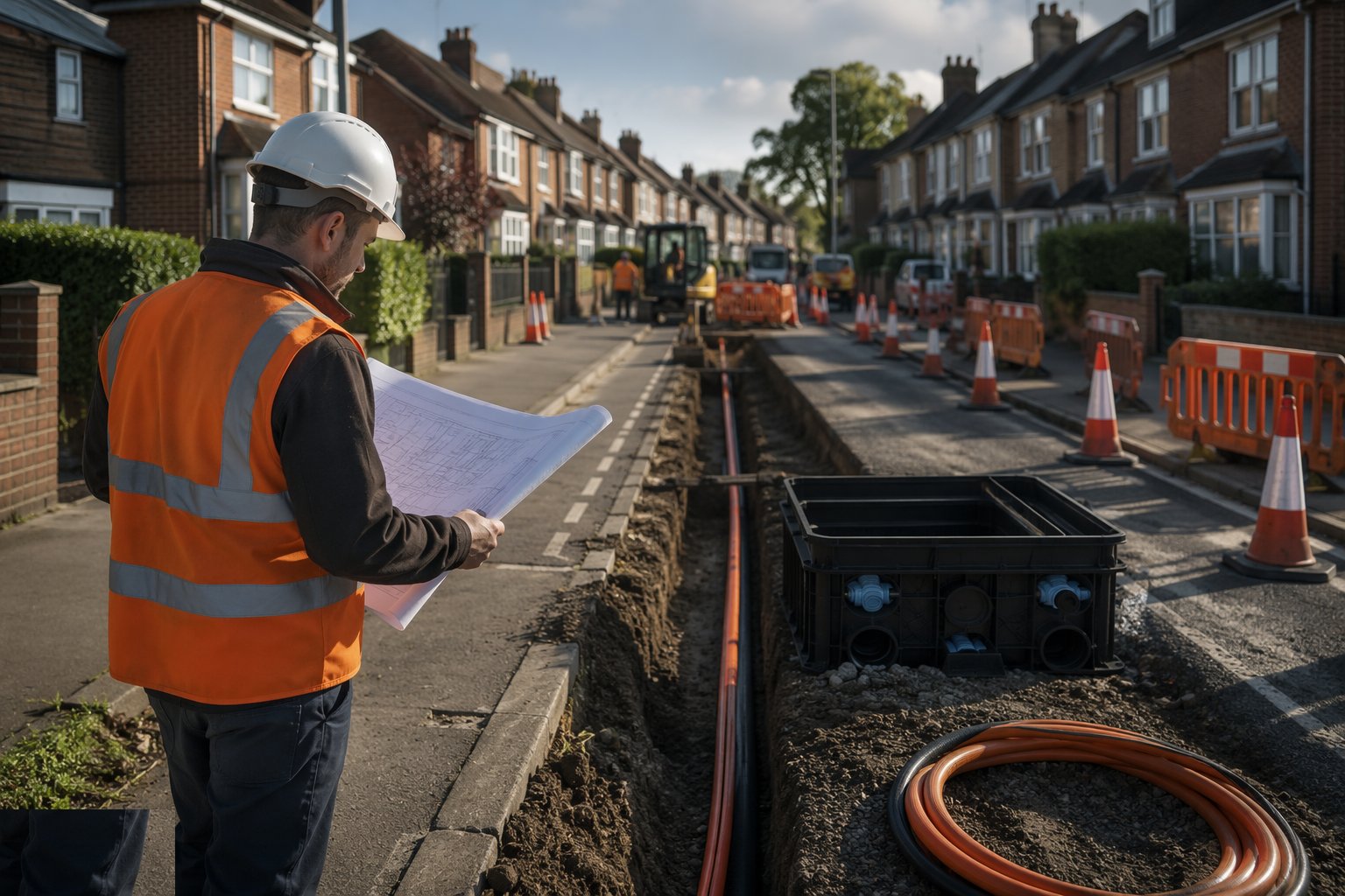
Everything starts with the records: statutory undertakers' plans requested and plotted, the route walked and scanned (GPR and CAT-and-Genny as a minimum, trial holes at congested crossings), and the design fixed for duct depth, chamber positions and crossing methods. Street works notices or permits go to the highway authority with the traffic management proposals — NRSWA governs the UK process, with fines for overruns and defective reinstatement; in the UAE the municipality and RTA equivalent issue the road-opening NOC alongside the telecom operator's own approvals. The permit conditions — working hours, lane rental on traffic-sensitive streets, board-and-barrow requirements — shape the programme more than the digging does.
Step 2: Excavate and lay the duct run
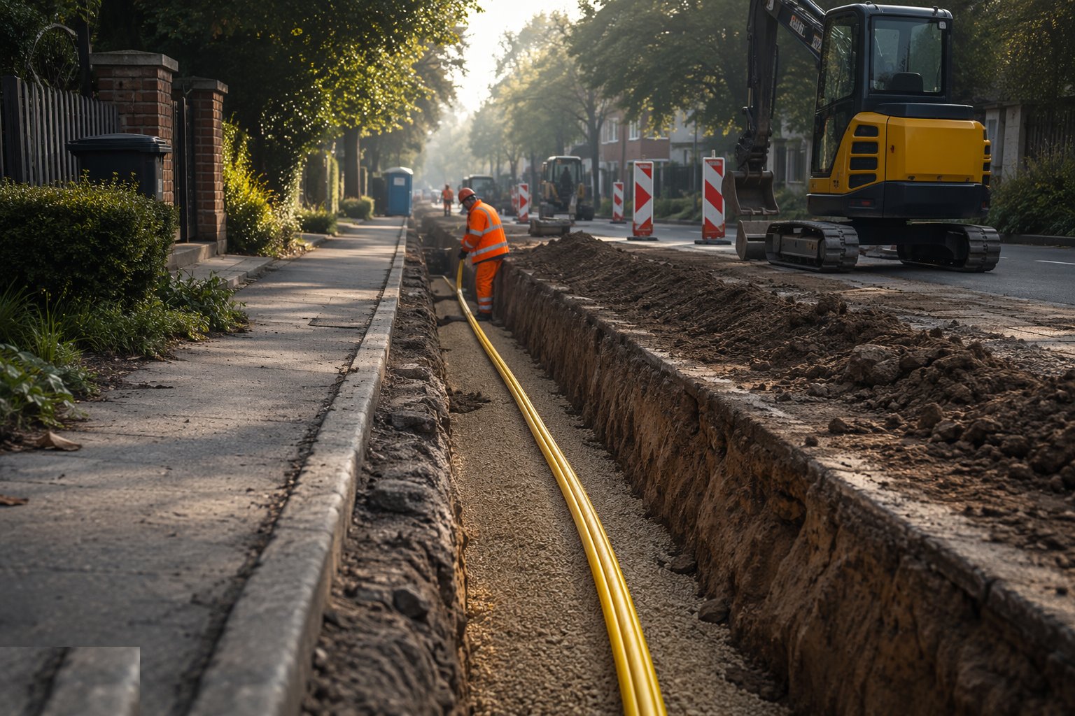
The trench is cut to line and depth — typically 300–450 mm in footways, 450–600 mm or more in carriageways, deeper where the spec or the frost/surface loading demands — with the formation trimmed and any water dealt with before bedding. Ducts are laid on a sand bed with spacers keeping multi-way formations true, jointed and mandrel-proven as they go, surrounded to the spec, and warning tape laid above before backfill in compacted layers. Bends are swept, never kinked — a kinked duct is a blown-fibre failure waiting for its moment. Every existing service crossed gets exposed by hand and protected; the day a bucket goes through a 33 kV cable is the day the job changes hands.
Step 3: Build the chambers
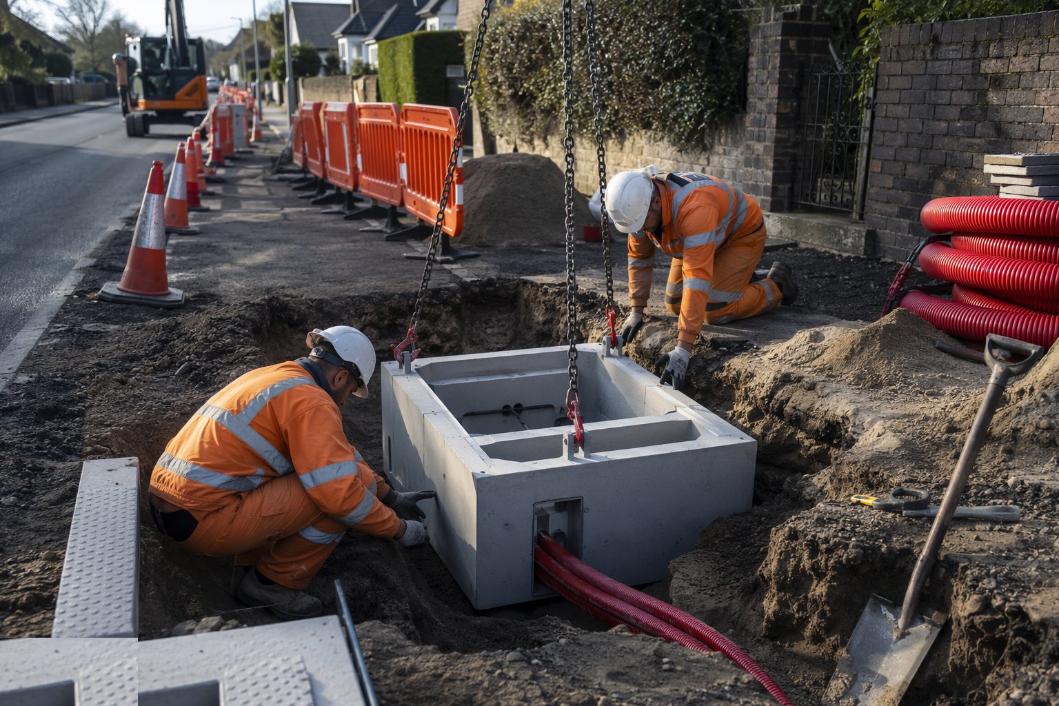
Jointing chambers are built at every design node: excavated, based in concrete, and walled in precast rings or modular blockwork with the duct entries formed and sealed. Ironwork — covers and frames — is bedded and haunched in concrete or mortar to the carriageway loading class, set to the finished surface level so it neither ponds water nor rattles under tyres. Depth is critical: shallow enough for the splicer to work without confined-space entry where possible, deep enough to keep the duct formation falling toward the chamber so water has somewhere to drain. Chamber positions are surveyed and recorded because in ten years the as-built drawing is the only map anyone trusts.
Step 4: Reinstate the highway
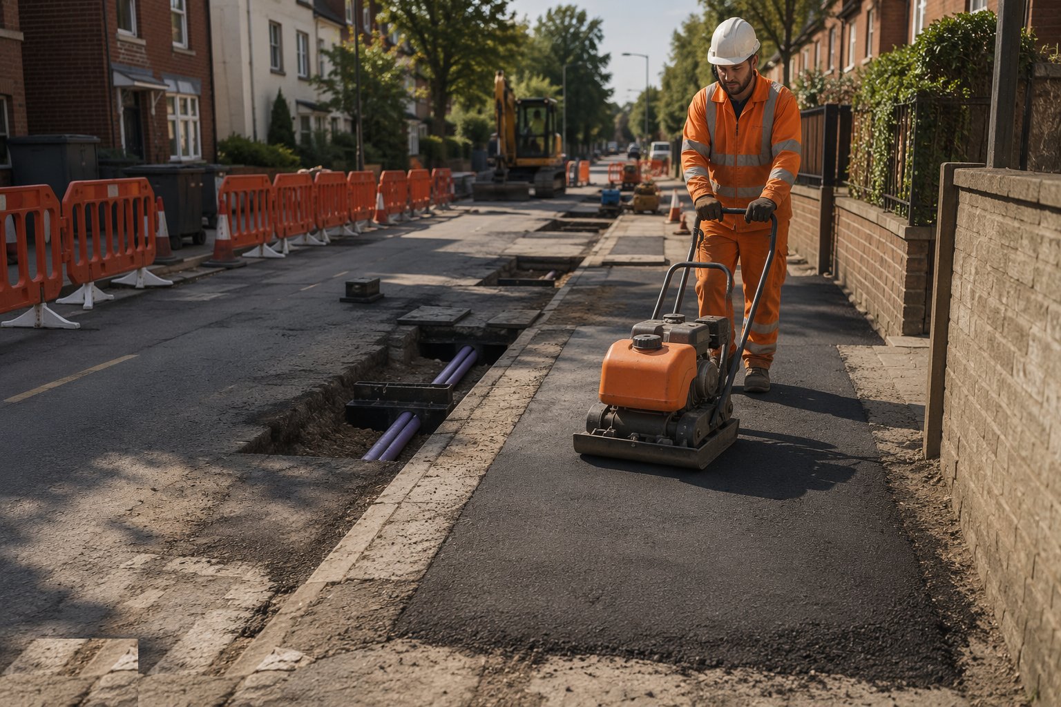
Reinstatement is a specification, not an afterthought: backfill in compacted layers with in-situ density checks where required, sub-base and base courses replaced to the SROH structure, and surfacing laid and compacted to match — or beat — the surrounding road. Microtrench slots get their flowing grout or proprietary cold-lay system, cured before trafficking. Every opening is logged for the guarantee period, because a sunken trench line across a carriageway is the most visible signature a telecoms contractor leaves, and highway inspectors photograph them for a living. Interim reinstatements are made permanent within the specified period — leaving a board-and-asphalt patch to weather a winter is how contractors earn embargoes.
Step 5: Blow or pull the fibre cable
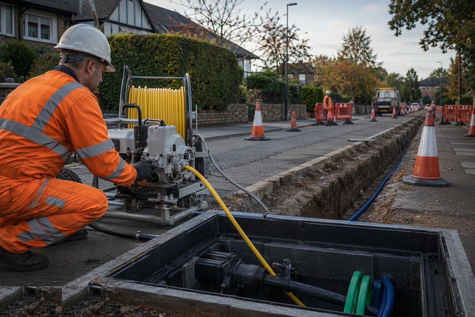
With ducts proven by mandrel and air test, the cable goes in. Blown installation feeds the cable off the drum into the duct on a head of compressed air, the air drag on the cable jacket doing most of the work so tension stays low — distances of a kilometre or more between chambers are routine on straight routes. Pulling is reserved for short runs, using a winch through a swivel with tension monitored against the cable's rated limit, because stretched fibre ages and dies early. Slack is coiled in the chambers on storage brackets at every joint point — the fibre you spare today is the repair length you need after the next excavator strike. Drum numbers, lengths and route positions are logged; the cable tally is the network's birth certificate.
Step 6: Splice, test and commission
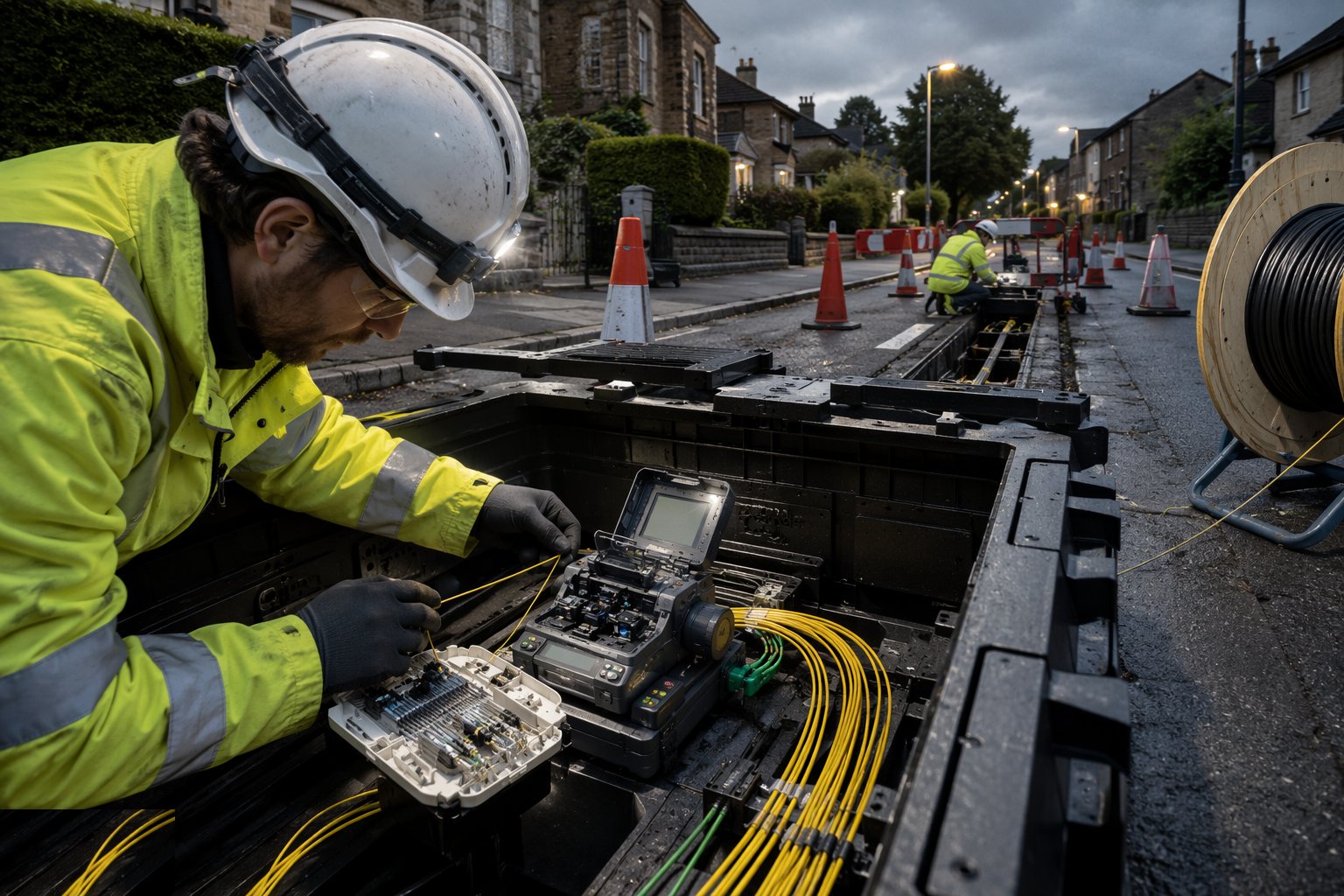
At every joint the splicer sets up in the chamber or the van: fibres stripped, cleaned, cleaved and fusion-spliced, each splice sleeved and laid in its tray with the minimum bend radius respected — bend a fibre past its radius and the light leaks out and the trace shows it. The enclosure is sealed, labelled and mounted, and the route is tested end to end: OTDR traces from both directions on every fibre, splice losses read against the budget (fractions of a dB per splice), connector reflectance checked, and the total link loss compared with the transmission design. Failures are re-spliced or re-terminated until the trace is clean — there is no arguing with an OTDR. The test file, the cable tally and the as-built route go to the operator, and the network is handed over lit or dark as the contract says.
Plant and equipment
- Excavators and vacuum excavators (for work near live services)
- Microtrenching rock-saw machines and slot-cleaning vacuum units
- Directional drilling rigs with tracking/locating systems
- Cable blowing machines, compressors and blowing heads sized to duct and cable
- Cable drum trailers, winches and tension-monitoring pulling gear
- Fusion splicers, cleavers and OTDR/light-loss test sets
- Mandrels, duct rodders and air-test kits for proving duct routes
- Chapter 8 traffic management: signs, barriers, lights and temporary signals
Quality control checks
- Duct depth, bedding and surround verified before backfill; mandrel and air-test records per section
- Chamber construction and ironwork loading class checked against the highway or operator specification
- Reinstatement layers and compaction verified; guarantee-period records kept per NRSWA/SROH
- Cable installation tension and drum tallies logged for every blown or pulled section
- Fusion splice losses read per splice; OTDR traces both directions on every fibre against the loss budget
- As-built route survey with chamber positions, duct formation and cable allocations issued to the operator
Safety considerations
- Excavations in live streets: supported, battered or boxed as the ground demands, with barriers and lighting day and night
- Buried services: scan, permit-to-dig and hand-dig or vacuum excavation near live plant — service strikes kill and bankrupt
- Traffic management to Chapter 8 maintained and audited; lone working rules for footway gangs at night
- Confined-space entry procedures for deep chambers: gas testing, ventilation, top-man and rescue arrangements
- Compressed-air blowing operations: hoses restrained, pressures regulated, eye protection at the duct mouth
- Glass fibre handling: sharps discipline for cleaved fibre ends, and no food or drink at the splice position
Common defects
- Duct laid shallow or kinked at bends, discovered when the blown cable stalls or the first utility diversion finds it
- Chamber ironwork set proud or low, rocking under traffic and cracking its haunching within a year
- Trench reinstatement under-compacted, leaving the tell-tale sunken line across the carriageway and an NRSWA defect notice
- Cable pulled beyond rated tension, passing testing on day one and failing by attenuation creep within seasons
- Splices made in wet or dirty chambers, with contamination losses that haunt the OTDR trace forever
- Chambers left without cable slack or labels, so the first repair crew opens a box of anonymous glass
Best suited for
- FTTH/FTTP rollouts building duct-and-fibre spines through residential streets
- Backbone and backhaul routes between exchanges, cabinets and mobile sites
- Carriageway crossings where microtrenching or drilling keeps the road open
- New development infrastructure where ducts go in with the other utilities before surfacing
How long does Fibre Network Installation take?
Typical duration: A footway duct-and-chamber crew advances 30–80 m per day depending on congestion; microtrenching runs several hundred metres per shift. Allow 8–20 weeks for a town-centre route of a few kilometres end to end, with permits and reinstatement driving the programme more than the digging..