Telecom Exchanges & Equipment Rooms
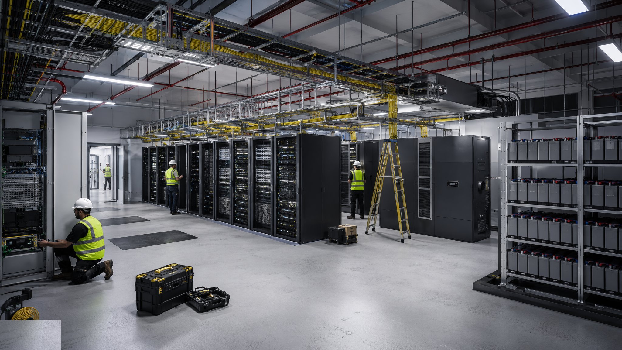
The building services side of the network — racks, DC power plants and battery strings, precision cooling and clean-agent fire suppression — fitted out inside buildings that have to stay live while you work on them.
Last updated 2026-07-28 by the BuildPedia Editorial Team.
What is Telecom Exchanges & Equipment Rooms?
A telephone exchange, a mobile switching centre or an operator's equipment room is, in construction terms, an MEP project wearing a hard hat. The payload is rows of 19-inch equipment racks; everything else exists to feed and protect them. Power arrives as metered AC, passes through switchgear into rectifier plants that produce the telecoms-standard −48 V DC, and is backed by strings of batteries — traditionally valve-regulated lead-acid, increasingly lithium — sized to carry the load for the hours it takes a generator to arrive or start. Lose the power chain and the site goes dark; lose it in a live exchange and people lose phone service, which is why resilience is designed in layers: dual feeds, N+1 rectifiers, batteries, and a generator socket or a standby set.
Heat is the second enemy. A rack row of transmission and switching equipment dumps kilowatts into a small room, and the cooling — DX split systems, CRAC units, or chilled-water fan coils on bigger sites — is sized with redundancy so one failed unit does not cook the room on a summer afternoon. Fire protection in these spaces is a specialism of its own: detection by aspirating smoke systems (VESDA-type) that sniff the air continuously for the earliest trace, and suppression by clean-agent gas systems — inert or chemical agents to the extinguishing concentrations — because flooding a live equipment room with sprinklers is only marginally better than the fire. Cable management ties the whole room together: overhead basket and ladder racking, separate routes for power, signal and fibre, and an earthing philosophy — the mesh bonding network — that keeps every metallic surface at the same potential.
Much of the work is not new-build but surgery on live buildings: adding rack rows to a working exchange, upgrading a DC plant without dropping the load, cutting in a new cooling system while the old one still runs. That makes phasing, permits-to-work and change control the real trade skills — every isolation is planned, approved and reversible, and every cable is labelled because the next engineer's mistake begins with your missing label. In the UAE these rooms sit under operator standards (Etisalat (e&), du), the UAE Fire and Life Safety Code for suppression and detection, and Civil Defence approval for the fire systems, with the added Gulf problem of keeping unconditioned plant spaces survivable before the cooling is commissioned — summer fit-out work in an exchange without AC is its own occupational hazard.
When and why is Telecom Exchanges & Equipment Rooms used?
This stage runs when the network needs somewhere to terminate: new exchanges and switching centres for capacity growth, equipment rooms in buildings taking fibre or mobile base-station hotels, and — the bulk of the market — upgrades inside existing live sites where capacity has outgrown the power or cooling plant. The design choices are driven by resilience class: a rural equipment room might accept a single rectifier shelf and a few hours of battery; a switching centre takes duplicated everything. DC power is retained because it is the industry standard the equipment is built for and because batteries integrate directly into the busbar; clean-agent suppression is chosen because the asset value and the live-service risk rule out water. Skimp on any layer — batteries under-sized, cooling without standby, suppression zoned wrong — and the room will teach you the lesson at 3 a.m. on the hottest night of the year.
Types of Telecom Exchanges & Equipment Rooms
New-build exchange fit-out
A purpose-built or shell-and-core space fitted from bare concrete: raised floor or slab, full containment, power chain from intake to busbar, cooling and suppression installed clean. The easy job — everything accessible, nothing live, programme governed by plant lead times rather than permits-to-work.
Live-site upgrades and expansions
Additional racks, bigger rectifier plants, more batteries or new cooling inside a working exchange. The construction is secondary to the migration planning: temporary supplies, staged cutovers in maintenance windows, and a tested rollback for every change, because the customer never agreed to notice your project.
Building equipment rooms and base-station hotels
Smaller rooms in commercial buildings housing fibre termination, multiplexers or mobile operator equipment — a few racks, a DC plant or UPS, split-system cooling and aspiration detection. Structurally simple, but they inherit the host building's constraints: riser routes, landlord rules, fire strategy and floor loading.
Outdoor and containerised plant rooms
Prefabricated cabins and containers with integrated power, cooling and suppression, craned onto a plinth at greenfield sites. The fit-out happens at the factory, so site work is plinth, ducts and connections — quality is built in, and the site risk shrinks to the lift and the hook-up.
Telecom Exchanges & Equipment Rooms: step by step
Step 1: Survey, isolate and prepare the space
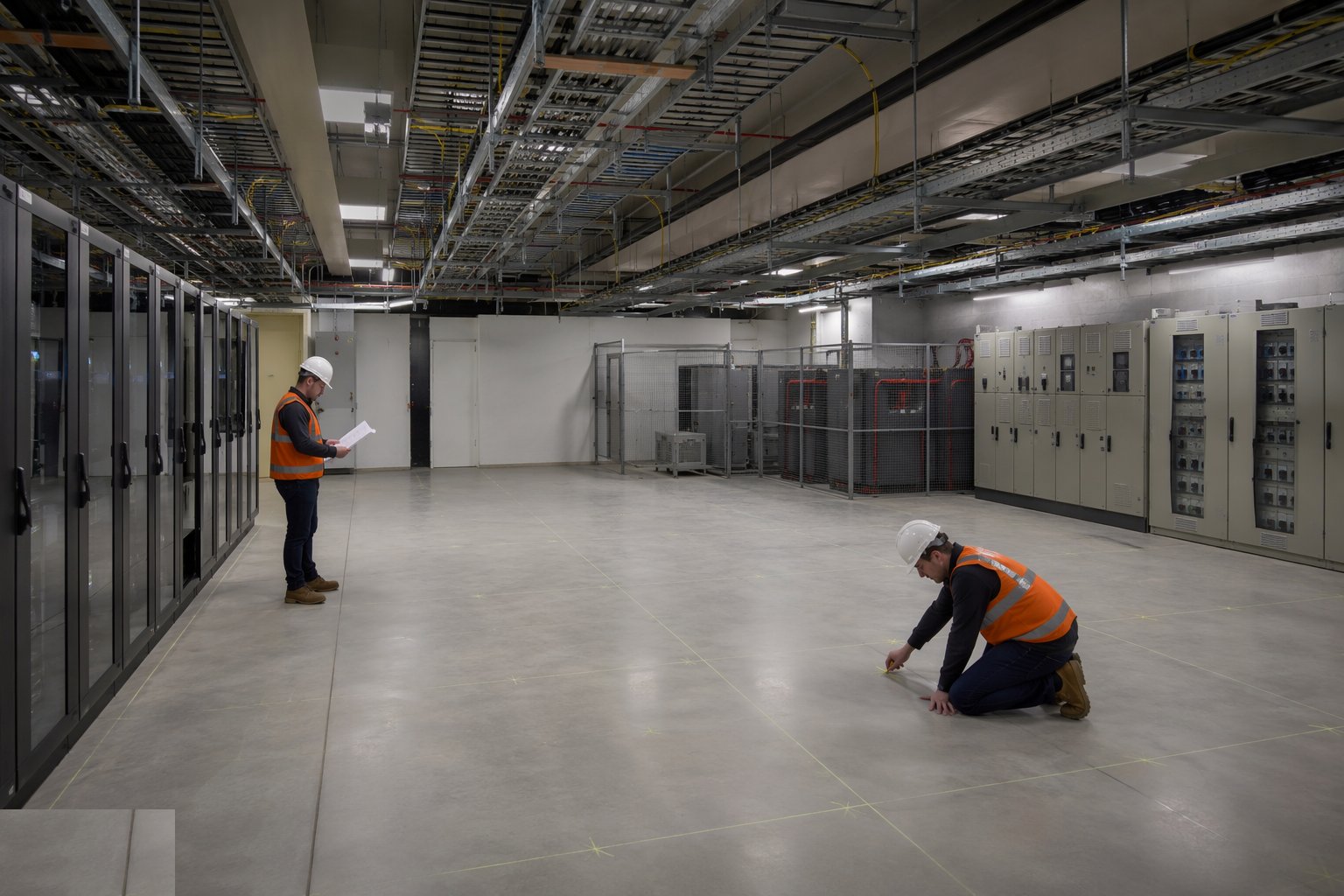
Every job starts with a survey even on new-build — but on live sites it is forensic: existing power single-lines walked and proven, every breaker and cable labelled against the drawings (which are always, somewhere, wrong), cooling capacity measured against current heat load, and the suppression zones mapped. A method statement and change plan is agreed with the operator for any work touching live services, with permits-to-work raised per task. The space is then prepared: strip-out of redundant frames, floor loadings checked against the battery and rack weights — a full battery string is tonnes on a small footprint — making good, and builder's work for containment supports and plant plinths.
Step 2: Install containment, earthing and cable routes
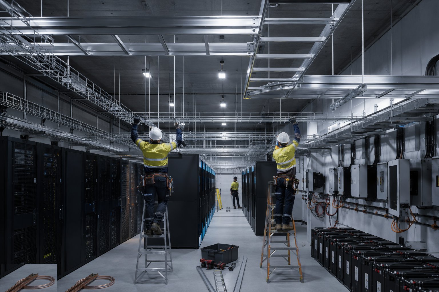
Overhead ladder racking and basket tray go up first, hung to the calculated loading with headroom preserved for the cooling airflow — containment installed without thinking about airflow creates hot aisles the CRAC units can never fix. Power, signal and fibre get segregated routes with the specified separation. The earthing network is installed as a system: main earth bar bonded to the supply earth and building steel, mesh bonding under or across the floor, and every rack and metallic run bonded back, because earth potential differences inside a live exchange cause faults that take weeks to diagnose. Fire-stopping of every new penetration follows immediately — an unsealed sleeve voids the room's suppression design and its compartmentation in one lazy omission.
Step 3: Build the power chain
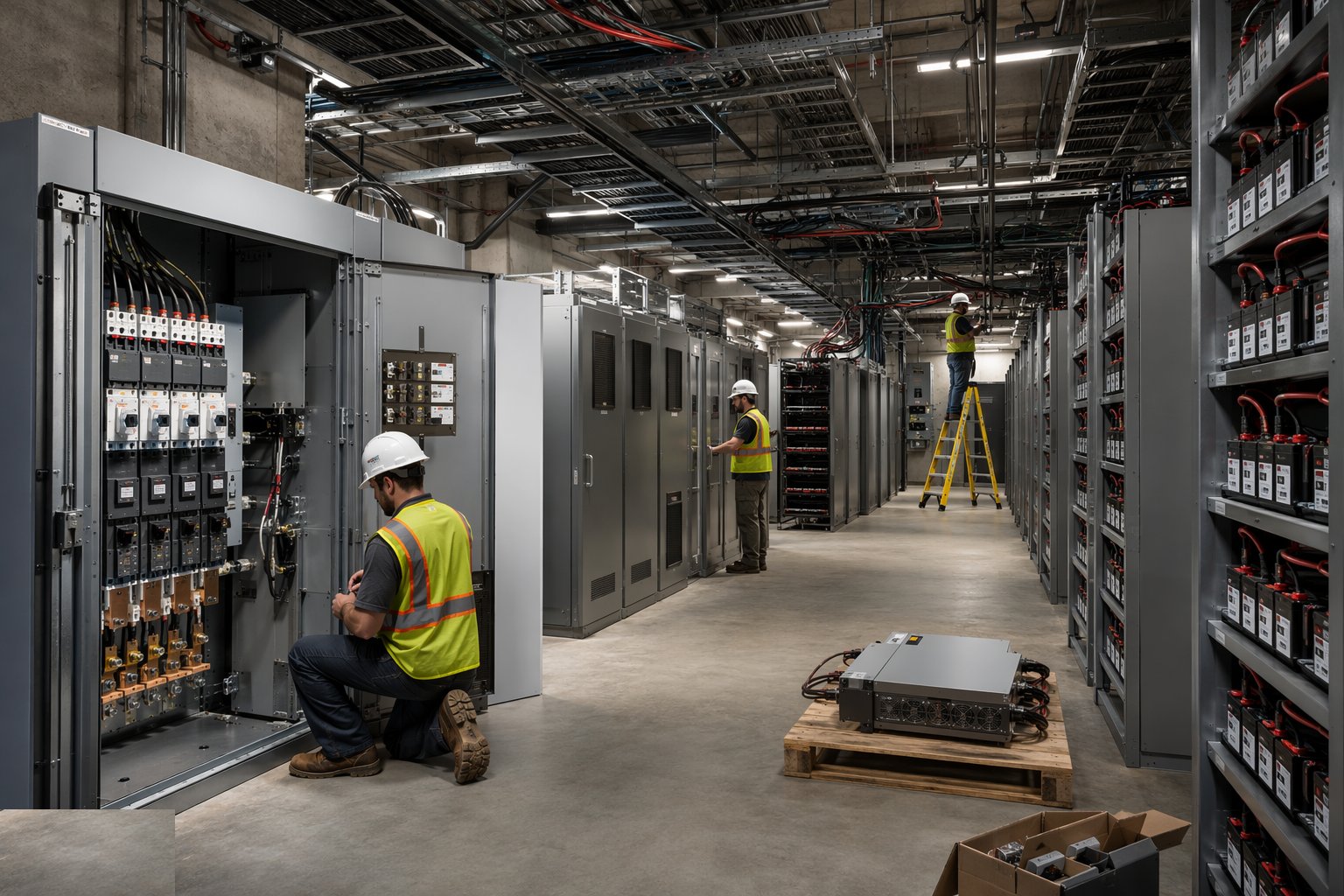
The power chain is installed from the intake outwards: AC switchgear and distribution boards, rectifier shelves producing −48 V DC, the DC distribution with its busbars and fused feeds, and the battery strings on their stands with inter-tier and inter-row connections torqued and recorded. Battery rooms get their ventilation, spill containment and eyewash — lead-acid strings are a chemical hazard as well as an electrical one. Changeover or generator provision is terminated and proven. On live upgrades this is the dangerous stage: temporary supplies carry the load, paralleling is planned to the letter, and the cutover runs in a maintenance window with the operator's engineer on the phone and the rollback rehearsed. Polarity is checked three times; −48 V DC connected backwards is expensive smoke.
Step 4: Land the racks and run the cabling
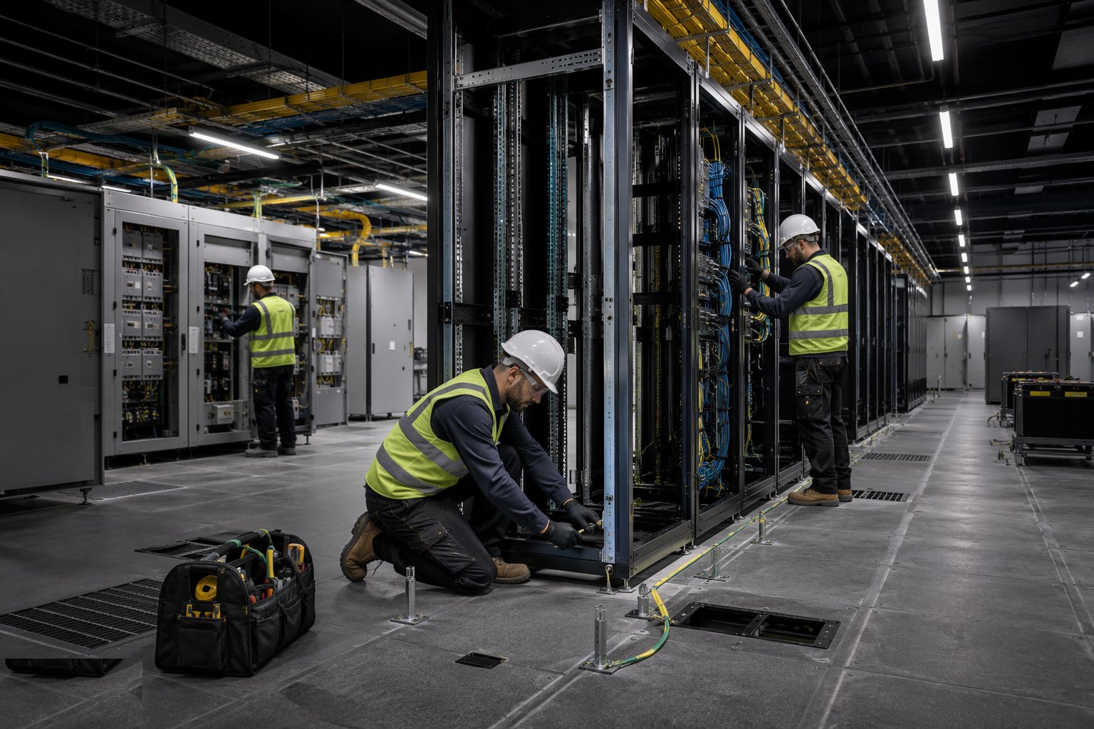
Racks are landed, levelled, bolted and bonded in rows set out from the containment design, with aisle widths kept for access and airflow. Cabling then runs on its segregated routes: DC feeds sized for volt-drop over the run (a long thin feed drops volts the equipment notices), signal cables dressed and labelled at both ends before they disappear into the tray, and fibre patch leads routed with bend radius respected through the management fingers. Every label is from the schedule, not from memory — in a room of ten thousand connections, the undocumented cable is the one that gets pulled at the wrong moment years later. Blanking panels and airflow management go in as the racks populate, not at the end when the hot spots are already mapped.
Step 5: Install cooling and fire systems
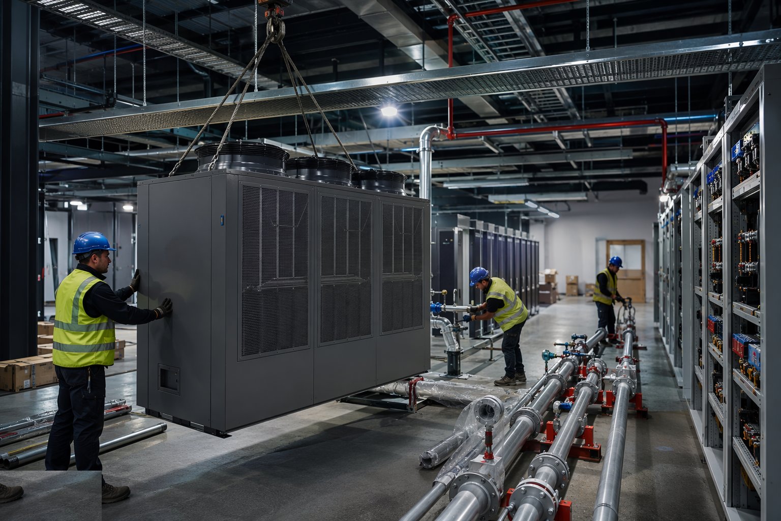
Cooling plant is set, piped and charged: CRAC units or fan coils positioned for the room's airflow logic, condensate drains run with traps and falls, and the standby unit proven by failover test, not by nameplate. The fire system follows: aspirating detection pipework sampled at the design points across the ceiling void and return-air paths, suppression cylinders manifolded to the protected zone, discharge pipework and nozzles positioned per the hydraulic design, and the room integrity tested — a door-fan test proves the enclosure will hold the extinguishing concentration for the retention time, because gas that leaks away in thirty seconds protects nothing. Cause-and-effect — detection to alarm to discharge to plant shutdown — is commissioned and witnessed.
Step 6: Test, integrate and hand over
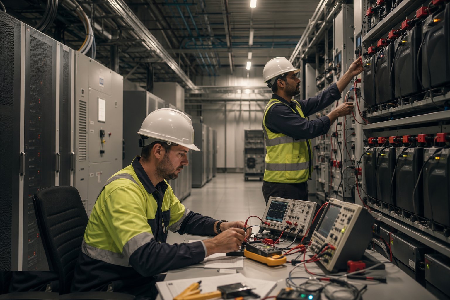
Commissioning proves every layer independently and then together: rectifier float and boost voltages, battery discharge or impedance tests against capacity, alarm and trip functions, cooling duty-and-standby cycling under load banks if the room is not yet populated, suppression cause-and-effect with discharge inhibited for the test. Integration with the network management system is proven — alarms have to reach the operations centre, not just sound in an empty room. The handover file carries the single-lines, the battery records, the room-integrity certificate, the earthing test results and the as-labelled schedules. On live sites the final act is removing the temporary supplies and standing the site down from project state to operational state, with the operator's acceptance signed before the permits close.
Plant and equipment
- Rectifier plants, DC distribution units and battery strings on stands
- CRAC units, DX splits and chilled-water fan coils with condensate pumping
- Clean-agent suppression cylinders, discharge pipework and aspirating detection panels
- Overhead ladder rack, basket tray and fibre-management systems
- Busbar and heavy DC cabling; hydraulic crimpers and torque tools
- Load banks for cooling and power proving; door-fan room-integrity test kit
- Insulated tools, DC-rated PPE and temporary power distribution for live working
- Earth bonding kits, clamp meters and battery impedance testers
Quality control checks
- Single-line verification of the installed power chain against design; polarity and voltage recorded at every stage
- Battery installation records: torque, interconnection checks and capacity or impedance test results
- Room-integrity (door-fan) test certificate for every clean-agent protected enclosure
- Cooling failover and capacity proven under load; condensate drainage tested wet
- Cable schedules reconciled against labels at both ends of every run
- Earthing continuity and earth-bar test results filed with the handover documentation
Safety considerations
- Live electrical working on DC plants: authorisation, insulated tools, covered busbars and a second person present — DC arcs do not self-extinguish politely
- Battery hazards: acid burns, hydrogen off-gassing requiring ventilation, and the sheer manual-handling weight of cells
- Permits-to-work and lockout discipline on live exchange sites; every isolation agreed and logged with the operator
- Clean-agent systems kept inhibited during works and reinstated under control — an accidental discharge in an occupied room is a life-safety event
- Manual handling of racks, rectifier shelves and cylinders with mechanical aids and planned routes
- Hot works and smoke-control coordination where the detection system is live — nothing trips a gas dump like uncontrolled grinding
Common defects
- DC feeds undersized for the run, so equipment at the far end browns out under peak load months after acceptance
- Batteries installed without torque records or ventilation, failing early and taking the resilience promise with them
- Containment laid out against the cooling airflow, creating recirculating hot aisles no setpoint can cure
- Unsealed penetrations and open doors leaving the suppression enclosure leaking its concentration — failed integrity test, or worse, a failed discharge
- Unlabelled or mislabelled cabling that turns every future fault into an archaeological dig
- Condensate drains trapped or graded wrong, dripping onto the racks the cooling was meant to protect
Best suited for
- New and expanded exchanges and switching centres with full power/cooling chains
- In-building equipment rooms for fibre termination and mobile base-station hotels
- Resilience upgrades to live sites where downtime is not negotiable
- Containerised plant rooms at greenfield sites needing factory-built quality
How long does Telecom Exchanges & Equipment Rooms take?
Typical duration: A new equipment-room fit-out runs 8–16 weeks depending on power-plant and suppression lead times; a live-site power or cooling upgrade runs similar weeks but at half speed, with the programme built around maintenance windows rather than working hours..