Telecom Towers, Masts & Rooftop Sites
The steel in the air — greenfield lattice towers and monopoles, rooftop stub masts and ballasted frames — founded, erected and dressed with antennas so the network has somewhere to hang its radios.
Last updated 2026-07-28 by the BuildPedia Editorial Team.
What is Telecom Towers, Masts & Rooftop Sites?
Every mobile network starts as a steel problem before it is ever a radio problem. A greenfield site is typically a fenced compound of 150–600 m² containing a tower or monopole, an equipment cabin or two, a power supply and a cable route back to the fibre network. The structure itself is one of three families: a self-supporting lattice tower in galvanised angle or tubular sections, good for 20–60 m and heavy multi-operator loading; a tapered steel monopole — the slip-jointed or flanged tube the planners prefer because it looks less offensive; or, in towns where the ground is already built on, a rooftop installation of stub masts, support steelwork and ballasted frames sitting on somebody else's building.
Foundations are unglamorous but they are where towers fall down — literally. A lattice tower usually stands on four pad foundations with holding-down bolt cages set to a jig, and the uplift on the leeward legs in a storm is as important as the bearing pressure on the windward ones. A monopole concentrates everything into one big pad or piled base with a ring of high-tensile bolts, and the bending moment at ground level is enormous: a 30 m pole with a headframe full of antennas and a 6 GHz drum of dishes is a very tall lever. Rooftop work inverts the problem — you are checking that someone else's slab can take your loads, which means pull-out tests on fixings, a structural survey of the existing frame, and often ballasted frames that hold everything down with concrete blocks so the waterproofing is never penetrated.
In the UK the work sits under the planning regime for electronic communications apparatus, CDM 2015, and the network operators' own build standards, with structural design to the Eurocodes and the mast industry's published guidance. In the Gulf the same physics applies with harder weather: design wind speeds, sand-laden gusts and brutal UV that eats polymer components, plus corrosion protection that has to survive a coastal salt atmosphere — hot-dip galvanising to BS EN ISO 1461 as a minimum, with duplex paint systems on anything the operator expects to last. Approvals run through the municipality and the telecom operator (Etisalat (e&) or du in the UAE), and rooftop sites add the landlord, the building permit authority and often Civil Defence for rooftop access and equipment room fire provisions.
When and why is Telecom Towers, Masts & Rooftop Sites used?
This stage comes first in the network build because nothing else — radios, fibre backhaul, power — has a home until the structure stands. Greenfield towers go where coverage geometry and land deals dictate: hilltops, motorway verges, farm corners. Monopoles go where the planning officer needs something slimmer, and rooftops go where the network needs height in a town it cannot buy land in. The method choice is made on loading, looks and ground: lattice carries the most kit per pound spent and tolerates future colocation, monopoles pass planning and fit tight corners, ballasted rooftop frames avoid drilling a stranger's waterproofing but limit you to whatever the existing slab can carry. Get the foundation or the wind-loading assumptions wrong and the structure tells you about it in the first winter gale, with the insurance industry close behind.
Types of Telecom Towers, Masts & Rooftop Sites
Self-supporting lattice towers
Three or four-legged galvanised steel lattice structures, erected in sections by crane or built up member-by-member with a gin pole. The workhorse of rural networks: highest antenna capacity, easiest colocation, and leg foundations that share the load across four modest pads.
Tapered monopoles
Single slip-jointed or flange-bolted steel tubes, 15–40 m, craned up in two or three sections in a day once the base is cured. Planner-friendly and compact-footprint, but every future antenna addition hangs off one shaft — headframe loading and sway limits get checked every time an operator wants to add a panel.
Guyed masts
Slender lattice columns held vertical by tensioned guy wires on anchor blocks spread well beyond the mast footprint. Cheapest steel per metre of height and common for broadcast and rural telecoms, but the anchor spread eats land and the guys need periodic re-tensioning — a maintenance commitment, not a fit-and-forget structure.
Rooftop stub masts and ballasted frames
Short masts (3–12 m) on steel grillages either bolted to the building frame or held down by concrete ballast blocks on protective mats. The default urban solution; the structural survey of the host building and the integrity of its waterproofing matter more than the steelwork itself.
Telecom Towers, Masts & Rooftop Sites: step by step
Step 1: Survey the site and prove the ground
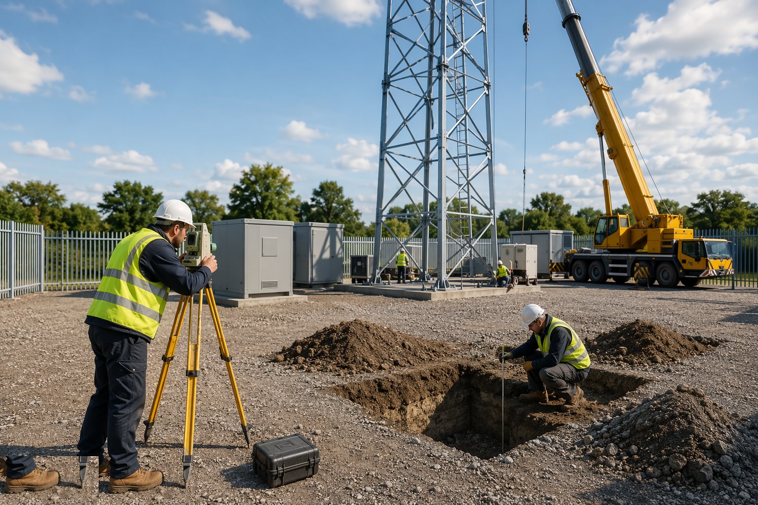
Before steel is ordered, the site is proved: topographical survey of the compound, geotechnical investigation to depth for the foundation design (trial pits or boreholes, with groundwater noted), a buried-services scan of the access route and compound, and for rooftops a full structural appraisal of the host building — as-built drawings hunted down, slab and frame checked by cover meter and pull-out tests where fixings are planned. The survey also fixes the access: a 30 m monopole arrives on an articulated lorry and the crane needs standing room, outrigger spread and overhead clearance from the very power lines the site is often built beside.
Step 2: Set out and construct the foundations
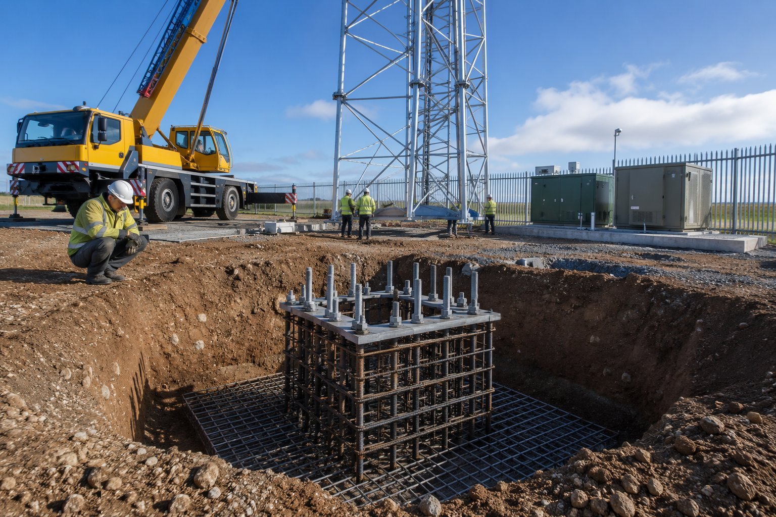
Pad foundations for lattice legs or the single monopole base are excavated to the design bearing stratum, blinded, and the reinforcement and holding-down bolt assemblies fixed. The bolt cage or ring is everything: it is set on a steel template jig, checked for level to a millimetre or two and for orientation so the door faces the compound gate, then braced so the pour cannot move it. Concrete is placed, cubes taken, and the base left to reach the specified strength before any steel lands on it — a monopole bolt ring cast 10 mm out of level becomes a leaning pole no amount of grouting fully forgives. In saline Gulf ground the mix gets sulphate-resisting binder and generous cover as standard.
Step 3: Pre-assemble and inspect the steelwork
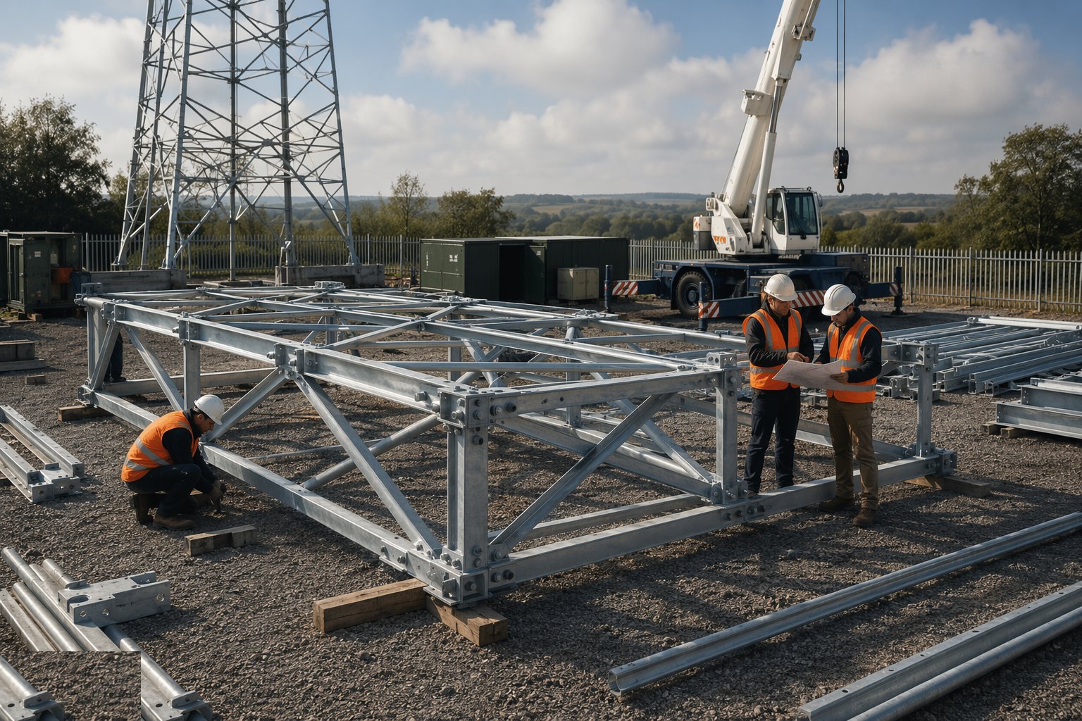
Delivered steel is checked against the fabrication drawings before it leaves the ground: section sizes, galvanising condition, hole alignment, bolt grades and quantities. Lattice tower sections are often pre-assembled at ground level into craneable lengths, with bolts torqued and marked as they go. Every bolted connection gets its specified grade — structural bolts are not interchangeable with whatever is in the van — and slip-jointed monopole sections are trial-matched at the works, not first met at height. Damaged galvanising is repaired with zinc-rich coating before erection, because a scratch at the bolt line is where a coastal atmosphere starts eating the tower.
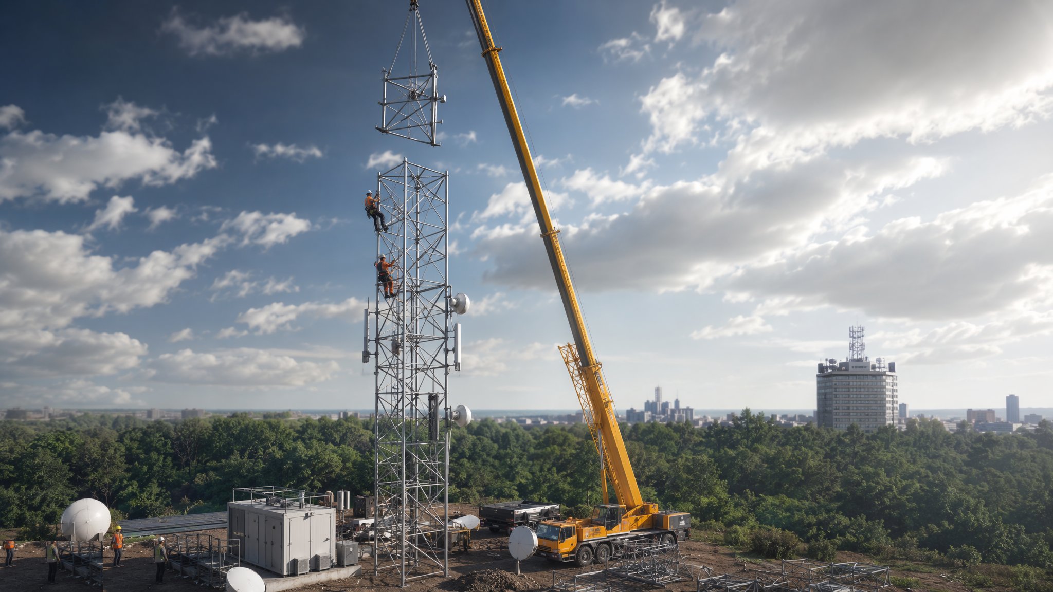
Step 4: Erect the structure by crane or gin pole
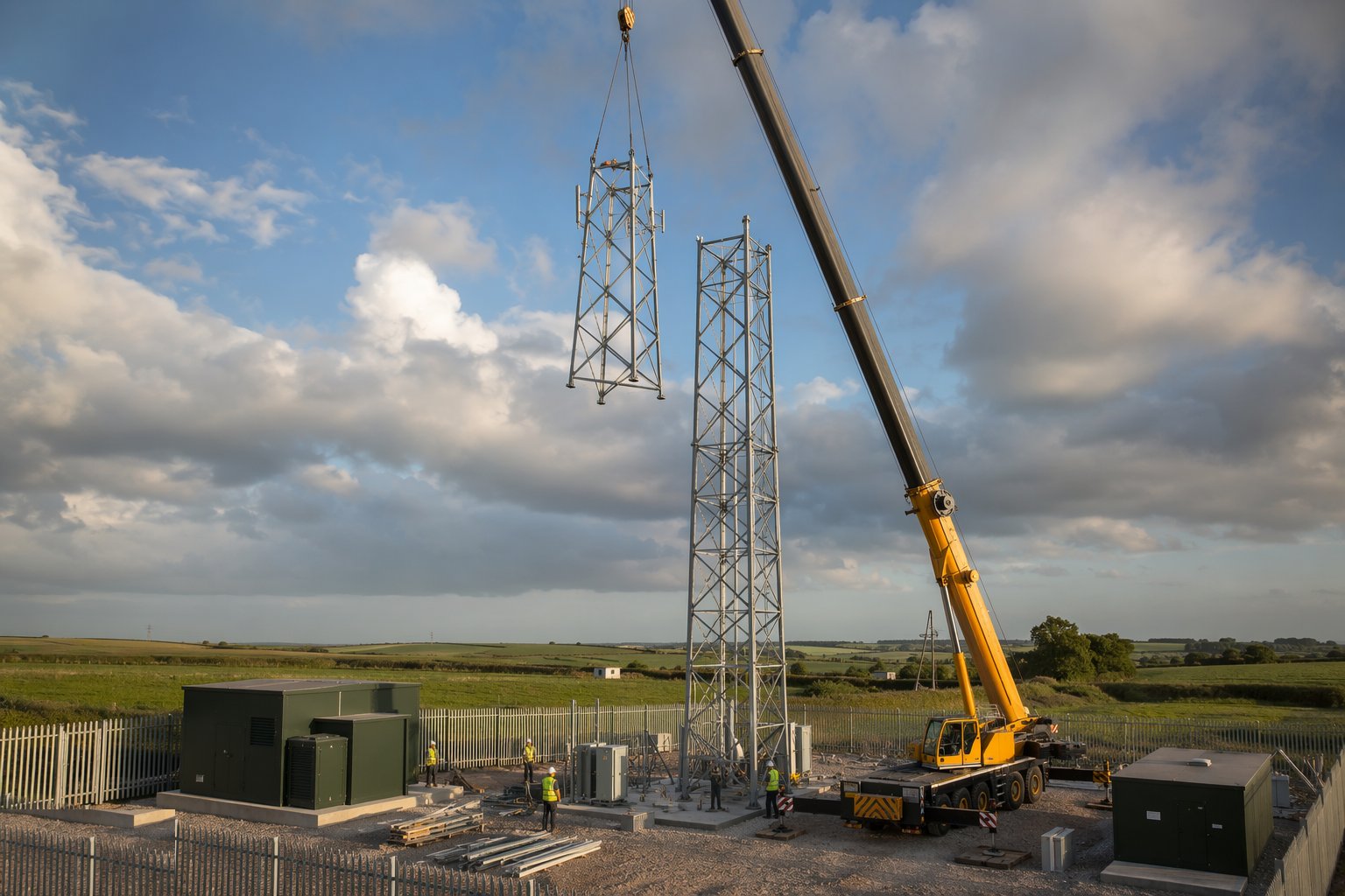
Crane erection is the fast route: sections lifted, bolted and plumbed in sequence, with the crane capacity checked at the actual radius for the heaviest lift — usually the top section with the headframe pre-fitted. Where no crane can stand, the old craft method takes over: a gin pole — a temporary derrick jumped up the tower as it grows — erecting member by member, slow but independent of access. Either way, verticality is surveyed as the structure rises, holding-down bolts are levelled and grouted with non-shrink grout once alignment is confirmed, and guys (where used) are tensioned to the calculated load with a dynamometer, not by eye. Wind limits on lifting are enforced hard: a headframe in a gust is a kite with a radio payload.
Step 5: Install antennas, dishes and feeder systems
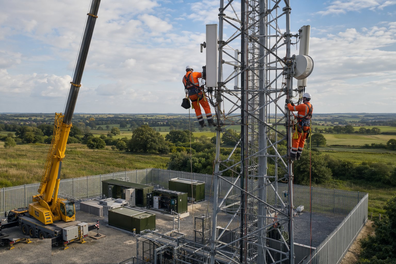
With the structure signed off, the riggers dress it: panel antennas mounted to azimuth and downtilt settings from the radio design, microwave dishes aligned path-to-path with the far end until the received signal peaks, feeders — coax or hybrid cables — run down the structure on cable ladders and secured at the specified centres, and GPS timing antennas sited with a clear sky view. Every connector is weatherproofed (butyl tape and cold-shrink, done properly, not a carrier bag and hope), and feeders are swept-tested and PIM-tested before acceptance. Azimuths set with a calibrated compass or theodolite matter: a panel 5° off its planned bearing is a coverage hole someone drives through every day.
Step 6: Build out the compound, power and earthing
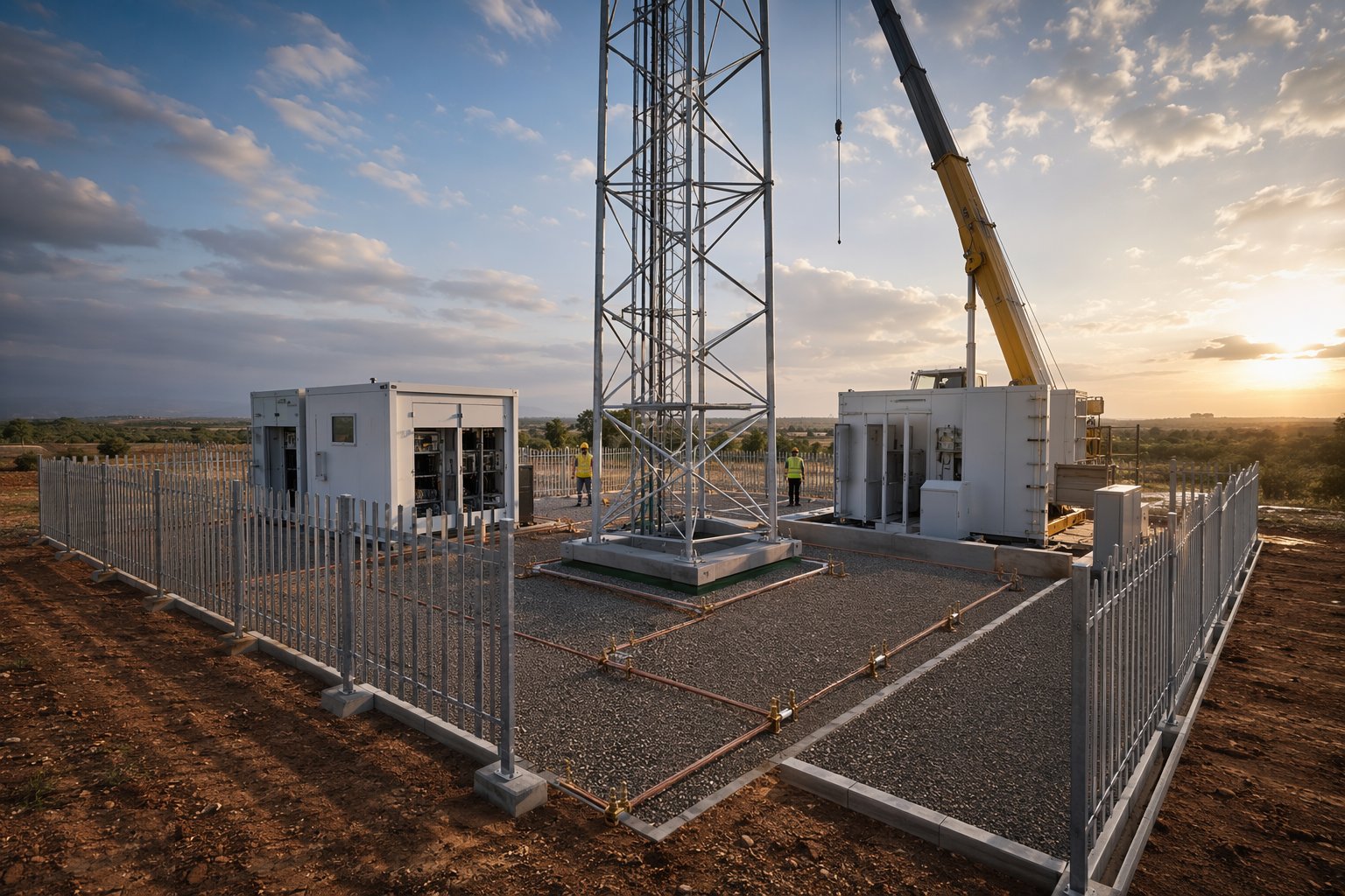
The ground work finishes the site: equipment cabins or outdoor cabinets landed on their plinths, the power connection made (DNO metered supply, or generator and battery backup where the grid is distant), and the earthing system installed — earth electrode rings around the tower base and compound bonded to every metallic element, because a 40 m steel structure is a lightning rod by profession. Feeder entry ports are sealed, compound surfacing laid (granular or concrete), palisade fencing and gates erected, and the duct route to the fibre network proven. In the UAE the operator NOC and municipality inspections close out this stage, and sites near the coast get their cabinets specified with corrosion-resistant finishes from day one.
Step 7: Test, survey and hand over the structure
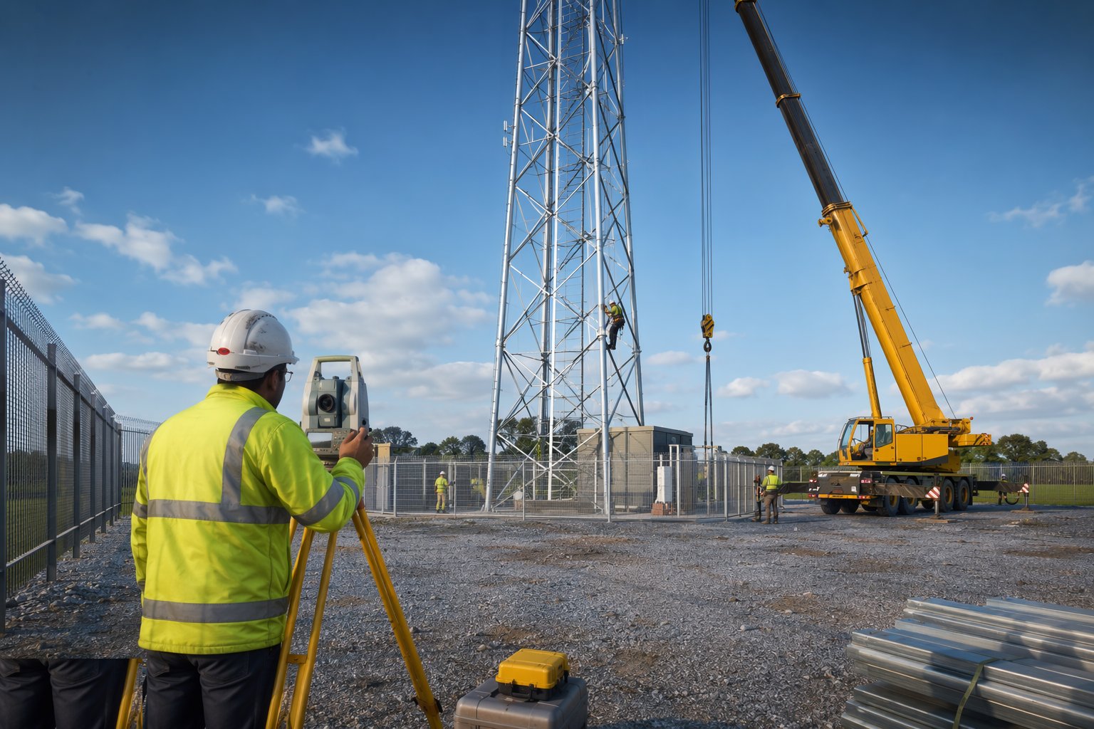
Handover is a paperwork exercise backed by instruments: final verticality and twist survey of the completed structure, bolt-torque verification records, foundation cube results, galvanising repair log, earth resistance test results, antenna azimuth and tilt records against the radio plan, and feeder sweep/PIM test certificates. The operator's structural acceptance and the rigger's as-built photographs close the file — and that file matters, because every future colocation request starts by asking what the structure was built for and what it is already carrying. A tower with no reliable as-built record gets re-surveyed at somebody's expense every time a new antenna is proposed.
Plant and equipment
- Mobile cranes sized for the heaviest section at radius, with rigging and tag lines
- Gin pole and capstan winches for member-by-member erection on restricted sites
- MEWPs and tower-mounted fall-arrest systems for antenna and feeder works
- Holding-down bolt jigs and templates; non-shrink grout and mixers
- Torque wrenches and tensioning equipment for structural and guy connections
- Total station or theodolite for verticality survey and antenna azimuth setting
- Cable sweep and PIM test sets; RF alignment receivers for dish paths
- Earth electrode installation kit and earth resistance testers
Quality control checks
- Holding-down bolt position, level and orientation verified on the jig before and after concreting
- Foundation concrete cube results confirmed to specified strength before erection loads the base
- Bolt grades verified against the fabrication specification; torque checks recorded per connection
- Verticality survey at each erection stage and at completion, against the design tolerance
- Antenna azimuth, downtilt and dish alignment records matched to the radio design
- Earth resistance test and galvanising repair records compiled for the handover file
Safety considerations
- Work at height on towers: competent riggers, twin lanyard or fall-arrest systems on climbing routes, and rescue-from-height plans rehearsed before anyone climbs
- Lifting operations under planned lifts with appointed persons, exclusion zones and wind limits enforced
- Dropped-object protection below riggers — tools tethered, hard barriers at ground level
- RF safety: antennas treated as live transmitters, exclusion zones observed, and coordination with the operator before working near radiating equipment
- Overhead and buried services: proximity to power lines controls crane standing positions; service scans before any excavation
- Weather holds — wind, lightning and, in the Gulf, midday summer heat rules for outdoor rigging work
Common defects
- Bolt ring or cage cast out of level or orientation, leaving a leaning monopole or mis-set door line that grout only partly disguises
- Galvanising damaged in handling and never repaired, so rust streaks start at bolt lines within the first wet season
- Wrong-grade bolts substituted at height, found (if found at all) years later in a colocation survey
- Feeder weatherproofing skimped at connectors — water tracking down coax kills the radio path a year after acceptance
- Antenna azimuths set by eye instead of instrument, producing coverage holes blamed on the radio planners
- Guy anchors under-designed or un-tensioned, letting the mast work loose and fret its connections
Best suited for
- Mobile and fixed-wireless network rollouts needing new structures
- Rural coverage where lattice towers and guyed masts give height per pound
- Urban infill where rooftop ballasted frames avoid planning and ground works
- Colocation upgrades adding operators to existing structures after structural review
How long does Telecom Towers, Masts & Rooftop Sites take?
Typical duration: A greenfield monopole site runs 6–10 weeks from possession to handover (half of it civils and power lead times); a lattice tower 10–16 weeks; a rooftop installation 4–8 weeks once the building survey and landlord consents are in hand..