Energy-from-Waste Plant Construction
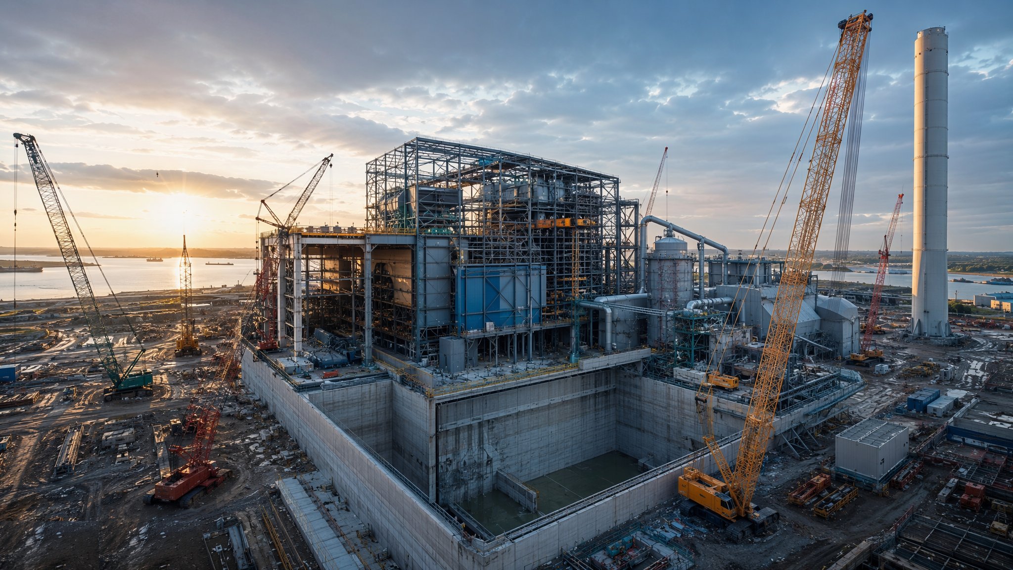
Power stations fuelled by rubbish — deep water-retaining refuse bunkers, boiler and turbine halls, flue gas treatment and a stack — built to process-plant tolerances on some of the heaviest civils in the industrial sector.
Last updated 2026-07-28 by the BuildPedia Editorial Team.
What is Energy-from-Waste Plant Construction?
An energy-from-waste plant burns residual waste and recovers the energy as steam, electricity and often heat. The process train reads: refuse bunker, where waste is stored and mixed by grab cranes; feed hoppers and the combustion grate; the boiler that turns the heat to steam; the turbine hall that turns steam to power; the flue gas treatment line — reagent injection, scrubbers, bag filters and NOx control — that cleans the exhaust to Industrial Emissions Directive standards; and the stack that disperses what remains. Capacities run from a hundred thousand tonnes a year to over half a million, and the buildings are sized by the process, not the architect: the bunker by refuse volume, the boiler hall by the grate and boiler modules, the stack by dispersion modelling.
The bunker is the defining civil structure: a reinforced concrete box commonly ten to twenty metres deep, designed as a water-retaining structure to BS EN 1992-3 because refuse is wet and leachate is aggressive, with mass concrete walls, waterstops at every joint, crack-width control, and drainage that collects leachate for disposal. It is cast like a basement box with a durability obsession — hot-weather rules on the mass pours, curing held for days, and a leak-tightness test before the cranes go on top. Above it sit the crane rails for the refuse grabs, and their alignment is measured in millimetres over tens of metres, because a grab crane that binds on a misaligned rail stops the plant's fuel supply.
Everything else is heavy industrial construction on a tight site. The boiler hall is a tall steel frame erected around equipment that arrives in modules weighing hundreds of tonnes, lifted by crawler cranes in choreographed heavy lifts. The turbine hall carries an overhead crane from day one because the turbine will need it forever. Flue gas treatment brings scrubber vessels, bag-filter houses, silos and kilometres of ductwork with expansion joints that live at high temperature. The stack — often sixty to a hundred metres — is slipformed as a concrete windshield with steel flues raised inside it. Commissioning is staged over months: cold, hot, first fire, first waste, then performance and emissions testing against the environmental permit, with continuous emissions monitoring certified before the plant is truly a power station.
When and why is Energy-from-Waste Plant Construction used?
EfW plants are built where residual waste policy, gate fees and energy prices make the arithmetic work — typically one plant serving a city region, on industrial land with road and grid connections. They matter because they displace landfill at scale and deliver baseload power and heat, and they matter to their builders because the programme is long — commonly three to four years — with the civils, the process vendor and the commissioning team on overlapping critical paths. The interfaces are where projects are won and lost: the bunker must be tight and true before the cranes and process arrive; equipment setting tolerances are millimetric; and the permit's emissions limits are proved by test at the end, so every weld, refractory lining and instrument is somebody's signature on a performance guarantee.
Types of Energy-from-Waste Plant Construction
Moving-grate EfW
The proven workhorse: waste burned on a reciprocating or roller grate, heat to a water-tube boiler, steam to a turbine. Most of the world's fleet, and the reference point for bunker, boiler hall and FGT design.
Fluidised-bed plants
Prepared refuse-derived fuel burned in a bubbling or circulating bed of hot sand. Higher combustion efficiency and lower NOx, but the fuel must be shredded and prepared — so the building gains a fuel-preparation line upstream.
Gasification and advanced conversion
Advanced thermal treatment that converts waste to syngas for engines, turbines or fuels. Smaller scale, higher technology risk, and process buildings packed with proprietary modules on tight tolerances.
RDF-fired dedicated plants
Plants burning refuse-derived fuel made elsewhere, with enclosed fuel reception and dosing instead of a raw-refuse bunker. Cleaner buildings, different civils — the fuel hall replaces the bunker as the defining structure.
Energy-from-Waste Plant Construction: step by step
Step 1: Heavy civils and the bunker excavation
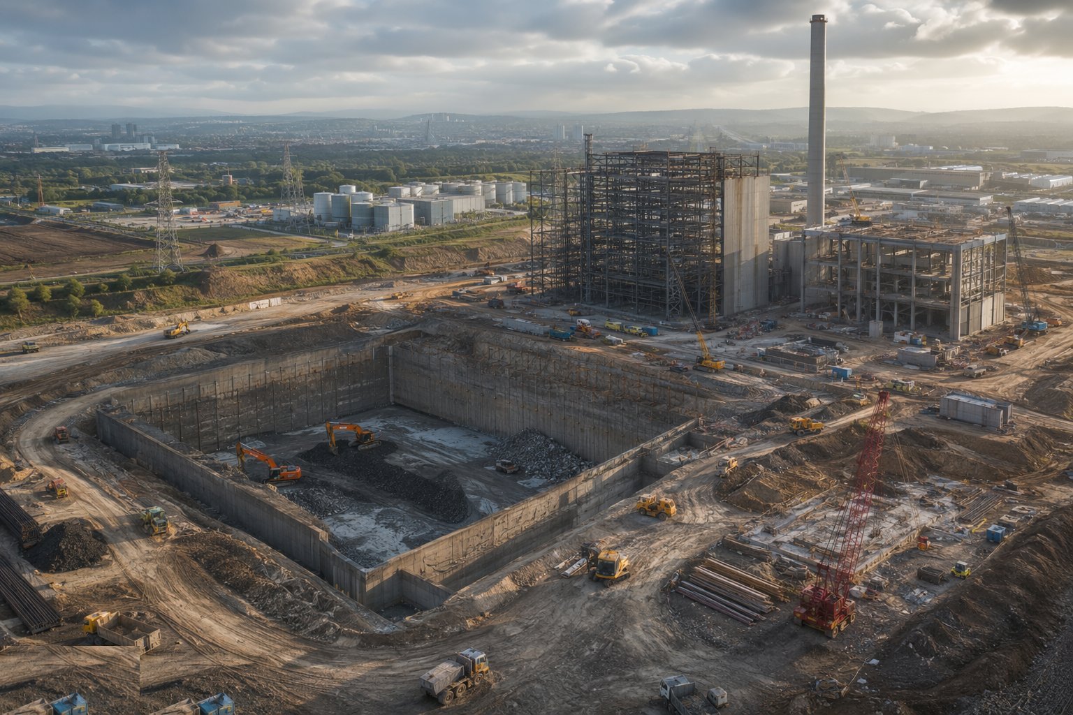
The site begins with earthworks at industrial scale: the bunker excavation taken down ten to twenty metres with designed temporary support — sheet piles, secant walls or battered sides as the ground dictates — dewatering where groundwater joins the party, and the formation inspected and blinded. Foundations for the boiler, turbine and FGT structures are cast as heavy rafts and plinths, some carrying dynamic loads with their own design criteria, holding-down arrangements set to template because retrofit anchors under a three-hundred-tonne module are not a conversation anyone wants. Craneage hard standings and heavy-lift pads are built early — the lifts define the site layout from the first month.
Step 2: Construct the water-retaining refuse bunker
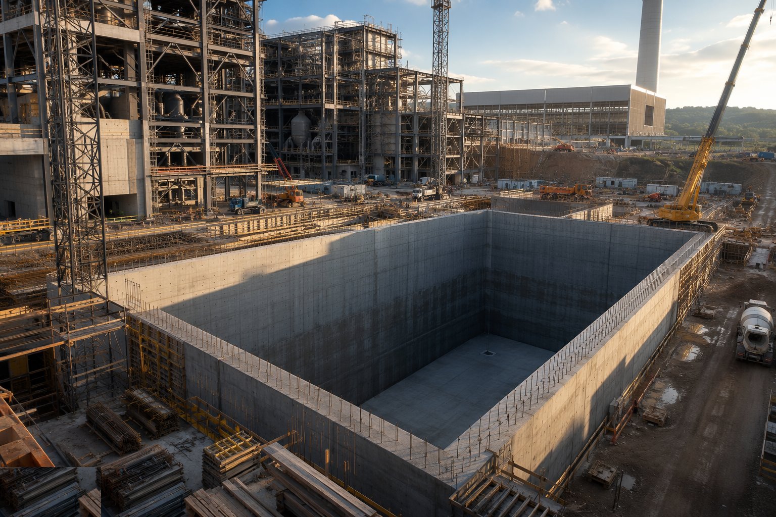
The bunker is cast as a water-retaining box to BS EN 1992-3: thick reinforced walls in carefully sequenced pours, waterstops fixed and checked at every joint, kickers cast true, crack-width control reinforcement to the durability design, and concrete placed and cured under strict thermal and moisture discipline — mass pours in summer get chilled mix, insulation and time. Internal finishes and leachate drainage follow: falls to sumps, protected drainage channels, and the leachate collection system sealed and tested. Before fit-out, the bunker is leak-tested and inspected; the record of that test is part of the permit evidence, because a bunker that weeps leachate into the ground is an environmental incident built in concrete.
Step 3: Erect the boiler and turbine halls
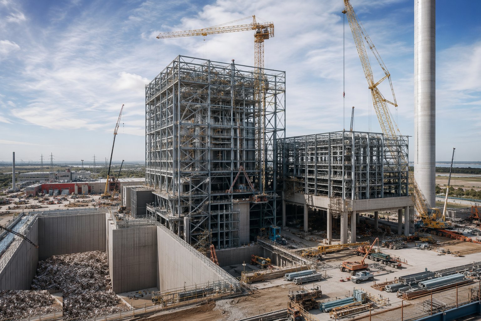
The halls rise as tall steel frames around the arriving process: columns and crane girders set and surveyed, the turbine hall overhead crane installed early because everything heavy below it will be placed by it, and the boiler hall steel erected in a sequence agreed with the process vendor — some modules go in before the steel closes over them, and the day the boiler drum is lifted is the day the frame sequence was designed around. Alignment is surveyed at every tier; equipment foundations are handed over with as-built surveys of bolts and pockets; and the cladding follows once the big lifts are in, because a clad building you cannot get the scrubber into is a very expensive box.
Step 4: Install the process plant
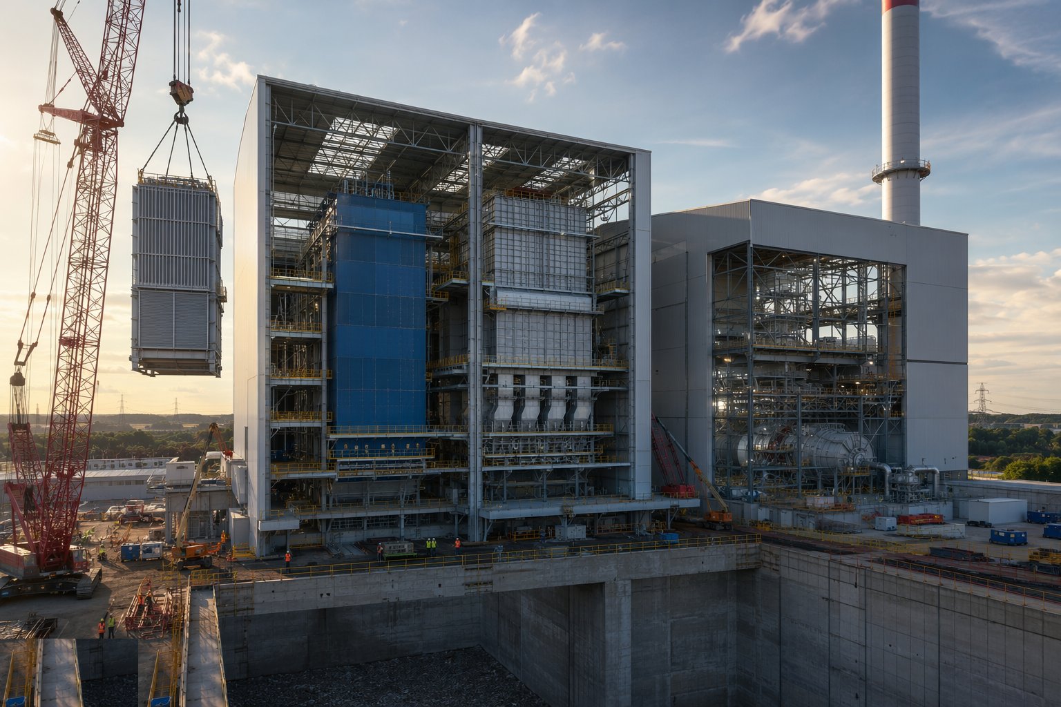
Process installation is months of heavy lifts and precision setting: the grate assemblies, boiler modules and economisers landed and aligned; the turbine and generator set on their plinths to laser-measured tolerances and grouted; refuse grab cranes erected on their rails with the rail alignment proven over full travel; conveyors, feeders and hydraulics fitted out. Pressure parts are welded by coded welders to approved procedures with the specified NDT and documented under the Pressure Equipment Regulations — every weld map and test record becomes part of the plant's legal file. Refractory and insulation follow the steel, with their own curing regimes that the commissioning programme must respect.
Step 5: Build the flue gas treatment line
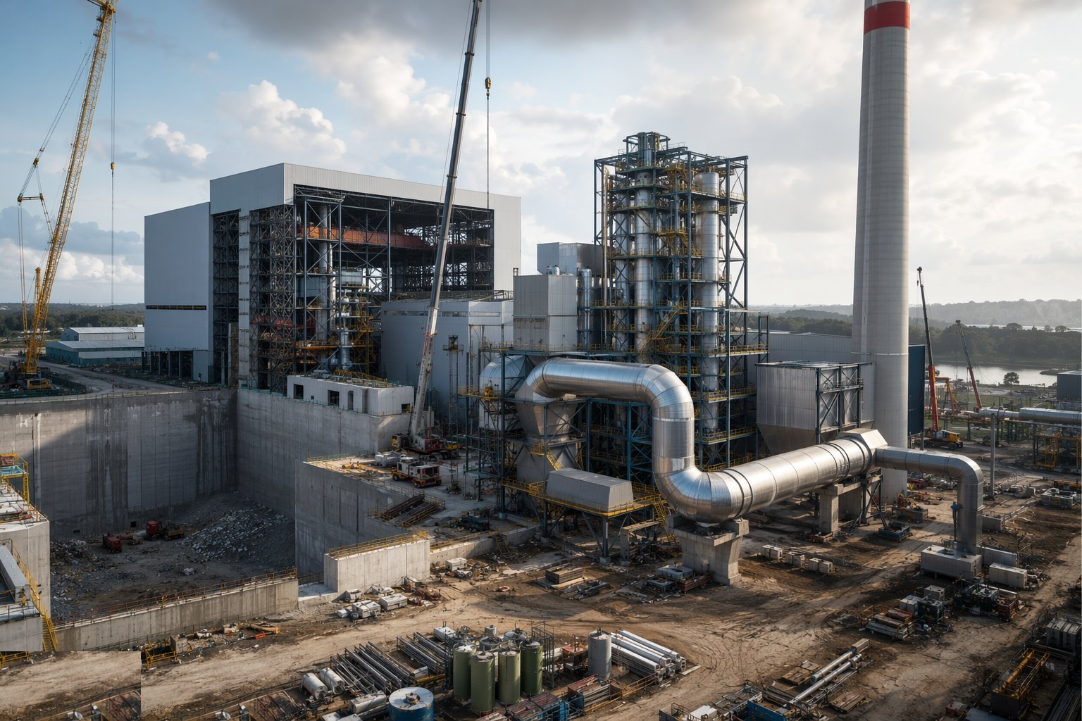
The FGT building and line are assembled as the plant's environmental licence made steel: reagent silos and dosing systems for lime and activated carbon, scrubber vessels set and piped, the bag-filter house erected with its cages, bags and pulse-cleaning systems, selective catalytic or non-catalytic NOx reduction installed, and the ductwork run between them with expansion joints, dampers and insulation rated for the temperatures and the acids. Instruments and the continuous emissions monitoring systems are mounted on their platforms with analyser houses and sample lines — the equipment that will testify, every minute of the plant's life, that the permit limits are being met.
Step 6: Raise the stack
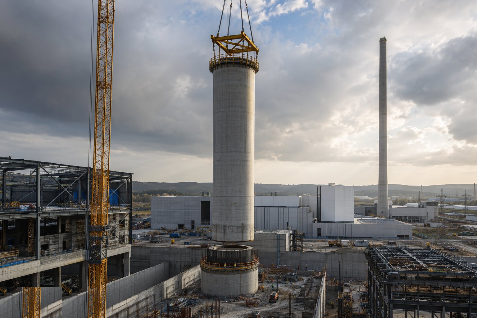
The stack is slipformed as a reinforced concrete windshield climbing continuously — the same 24-hour pour discipline as any slipform core, with geometry, verticality and twist surveyed as it rises — then the steel flues are installed inside it in sections, lifted through the top or built up on internal platforms, on guides that let them expand with heat. Aviation warning lights, access ladders and platforms, lightning protection and the CEMS sample points are fitted out as the flues rise. The stack is usually the tallest thing for miles and the last structure finished; it is also the plant's public face, and the quality of its concrete is read by everyone who drives past.
Step 7: Commission in stages to first waste
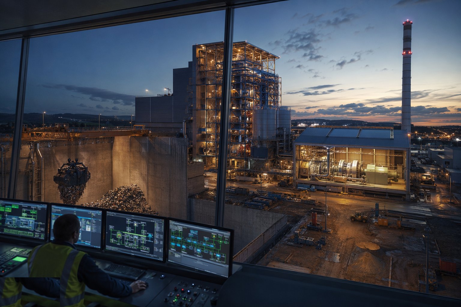
Commissioning is a programme in itself: systems flushed, blown and tested cold; refractory dry-outs run to the manufacturer's curves; first fire on auxiliary fuel; steam blows to clean the lines; turbine run-up and grid synchronisation; then first waste, ramped carefully while the combustion and FGT systems learn the fuel. Performance and emissions tests follow against the guarantees and the permit — throughput, availability, emissions over certified test periods with the CEMS validated. Handover assembles the O&M manuals, the weld and NDT files, the test certificates and the spares; the plant then enters its defect and optimisation period, where the builder's and vendor's reputations are finally settled by the availability statistics.
Plant and equipment
- Heavy crawler cranes — 300-tonne class and above — with configured heavy-lift pads
- Slipform rigs for the stack, with continuous concrete supply and standby plant
- Concrete pumps and placing booms for mass bunker pours
- Dewatering plant and excavation support systems for the deep bunker dig
- Steel erection kit: MEWPs, torque equipment, alignment lasers and survey instruments
- Welding sets, NDT equipment and coded welders for pressure parts
- Refractory installation and dry-out equipment with controlled heating
Quality control checks
- Bunker leak-tightness test records and waterstop continuity sign-offs per pour
- Concrete durability verification: cover surveys, crack-width checks and mass-pour temperature logs
- Crane rail alignment surveyed over full travel and certified before crane erection
- Equipment setting records: laser-aligned plinths, grout tests and as-built surveys per machine
- Pressure-part weld maps, procedure approvals and NDT records under the Pressure Equipment Regulations
- CEMS certification and witnessed emissions test results against the environmental permit
Safety considerations
- Heavy lifting over live areas: lift plans, exclusion zones and a single lifting authority across overlapping contractors
- Deep excavation and dewatering: supported sides, monitored ground, and controlled access to the bunker dig
- Work at height on tall steel and the stack: edge protection, MEWP discipline and wind limits on lifts
- Confined spaces — bunker, boiler, flues and ductwork: entry permits, gas testing, ventilation and rescue plans
- SIMOPS management as civils, steel, process and commissioning overlap: coordinated permits and one site rules document
- Hot commissioning hazards: steam, pressure and first-fire procedures with exclusion and communication protocols
Common defects
- Bunker walls weeping at joints — displaced waterstops or cracked mass pours discovered at the leak test or worse, at first waste
- Crane rails misaligned over length: grab cranes binding, wheel wear, and fuel supply interruptions
- Ductwork expansion joints failing early from wrong installation gaps or cold-side condensation corrosion
- Refractory spalling in the first campaigns — dry-out curves rushed to protect the programme
- Stack flue corrosion from material or drainage details that ignored the acid dew point
- Bunker tipping-floor drainage ponding leachate because falls and channels were built to the drawing's intent, not its levels
Best suited for
- Residual waste treatment at city-region scale with energy recovery
- District energy schemes coupling power with heat offtake
- Long-term waste infrastructure where landfill diversion economics hold
- Industrial sites with grid, road and reagent logistics to hand
How long does Energy-from-Waste Plant Construction take?
Typical duration: A mid-scale EfW plant typically runs 30–48 months from enabling works through first waste to performance testing, with the bunker and stack on the civil critical path and commissioning adding six months or more after mechanical completion..