Landfill Engineering & Capping
Engineered containment that has to work for decades — cells lined with compacted clay and welded geomembranes, leachate and landfill gas collected, then capped and restored — with every layer verified by a CQA engineer before the next covers it.
Last updated 2026-07-28 by the BuildPedia Editorial Team.
What is Landfill Engineering & Capping?
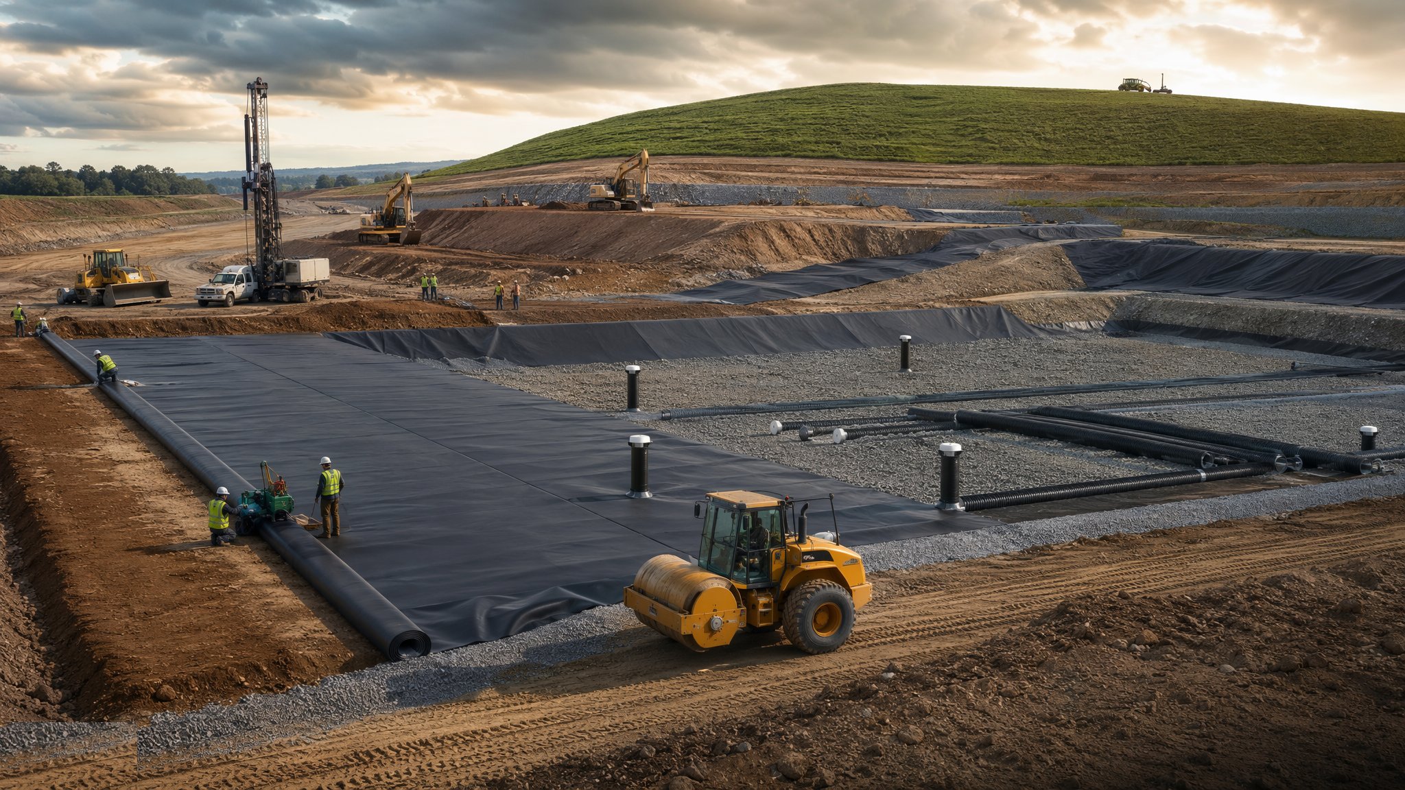
A modern landfill is not a hole that waste goes into; it is an engineered containment system that waste is placed inside. The barrier system is built in layers with regulatory minimums behind it: a geological barrier of suitable ground, then an artificial liner — compacted clay placed in controlled lifts to a permeability of 1 × 10⁻⁹ m/s or better, or a geosynthetic clay liner — then a flexible membrane liner of high-density polyethylene, typically 2 mm, welded panel to panel across the entire cell, then a protection layer of geotextile fleece, and finally a drainage layer of stone or geocomposite carrying leachate to collection pipes and sumps. Each layer is inspected, tested and signed off by the construction quality assurance engineer before the next is placed, because once the waste goes in, no one will ever see the liner again — it simply has to work, unseen, for longer than the people who built it will live.
The two fluids the site must manage forever are leachate and gas. Leachate — the contaminated liquor draining from the waste — is collected in perforated pipes bedded in the drainage layer, drawn to sumps and pumped to treatment or tankered disposal, with levels monitored so the head on the liner stays within the permitted depth. Landfill gas — methane-rich and dangerous — is collected from vertical wells and horizontal collectors installed as the waste rises, piped through a header main to flares or gas engines generating power. Both systems are civil engineering laid inside a refuse pile: pipes and wells that must survive settlement measured in metres, anchored, telescoped and detailed accordingly.
Capping is construction in reverse, and just as engineered: a regulation layer graded over the waste to the restoration profile, a gas-collection layer or low-permeability membrane to control what escapes, a drainage layer to shed infiltration, then restoration soils — subsoil and topsoil — and the final surface returned to agriculture, habitat or amenity. Capping is done progressively, cell by cell, because every acre capped is an acre no longer making leachate from rainfall. After closure the site enters aftercare measured in decades: leachate managed until it runs acceptable, gas managed until it fades, settlement monitored until the ground is stable. The permit is only surrendered when the Environment Agency agrees the site no longer poses a risk — and that agreement is earned by records that started with the very first CQA report on the very first clay layer.
When and why is Landfill Engineering & Capping used?
New landfill cells are built where permitted void space remains an asset — quarry restorations and strategic residual-waste capacity — and capping campaigns run continuously on operating and closing sites. The work matters because the failure modes are measured in groundwater contamination and uncontrolled gas migration: a liner defect is not a defect you repair, it is one you prevent, which is why the CQA regime is absolute and the verification reports gate every stage. It also matters commercially: a well-engineered cell maximises airspace, a progressive cap cuts leachate treatment costs, and a clean restoration profile is the difference between surrendering the permit in decades and fighting for it forever.
Types of Landfill Engineering & Capping
Compacted clay liners
Low-permeability barriers built from selected clay placed and compacted in lifts with strict moisture and density control — typically a metre or more total thickness. The traditional engineered barrier: cheap material, expensive discipline, and a sworn enemy of drying and cracking.
Geomembrane and composite liners
HDPE flexible membrane liners, typically 2 mm, welded across the cell with tested seams — alone, or composite over compacted clay or a geosynthetic clay liner so any leakage path meets resistance. The critical waterproof skin of the containment system.
Leachate drainage and collection
Drainage stone or geocomposite layers, perforated collection pipework, sumps, pumps and rising mains that keep the leachate head off the liner. The plumbing of a structure nobody can access again — built once, built right.
Landfill gas collection systems
Vertical wells drilled or built as filling rises, horizontal collectors within the waste, header mains, condensate knockouts and the flare or engine compound. Gas infrastructure engineered to survive metres of settlement without shearing.
Capping and restoration profiles
Regulation layers, gas membranes, drainage layers and restoration soils placed to the final landform, then soiled and vegetated. The permanent roof of the site — shedding water, controlling gas and carrying the after-use.
Landfill Engineering & Capping: step by step
Step 1: Prepare the formation and cell
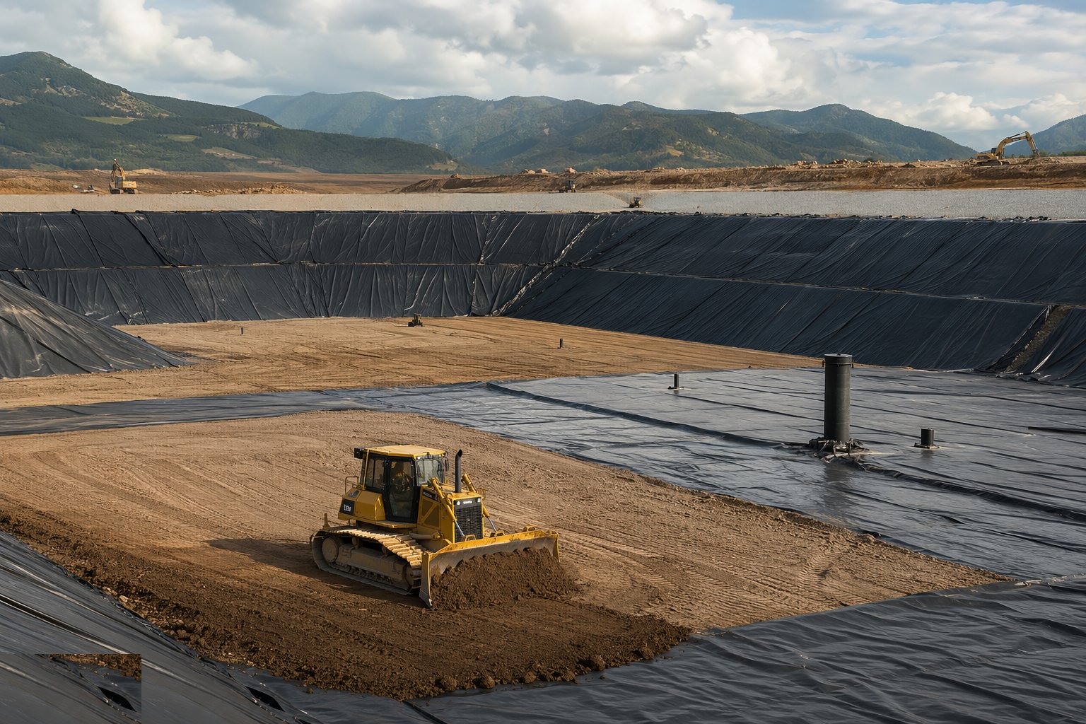
Cell construction starts with earthworks: the void excavated or re-graded to design, side slopes cut or filled to stable angles, and the formation graded to falls that drive leachate to the sumps. The formation is proof-rolled, inspected and accepted — soft spots out, sharp protrusions off, and the surface smooth enough that a geomembrane can lie on it without point loads. Survey control is established and the as-built record begins here, because every layer from now on is buried evidence: levels, extents and acceptance records that the verification report will carry for the life of the permit.
Step 2: Place the compacted clay liner
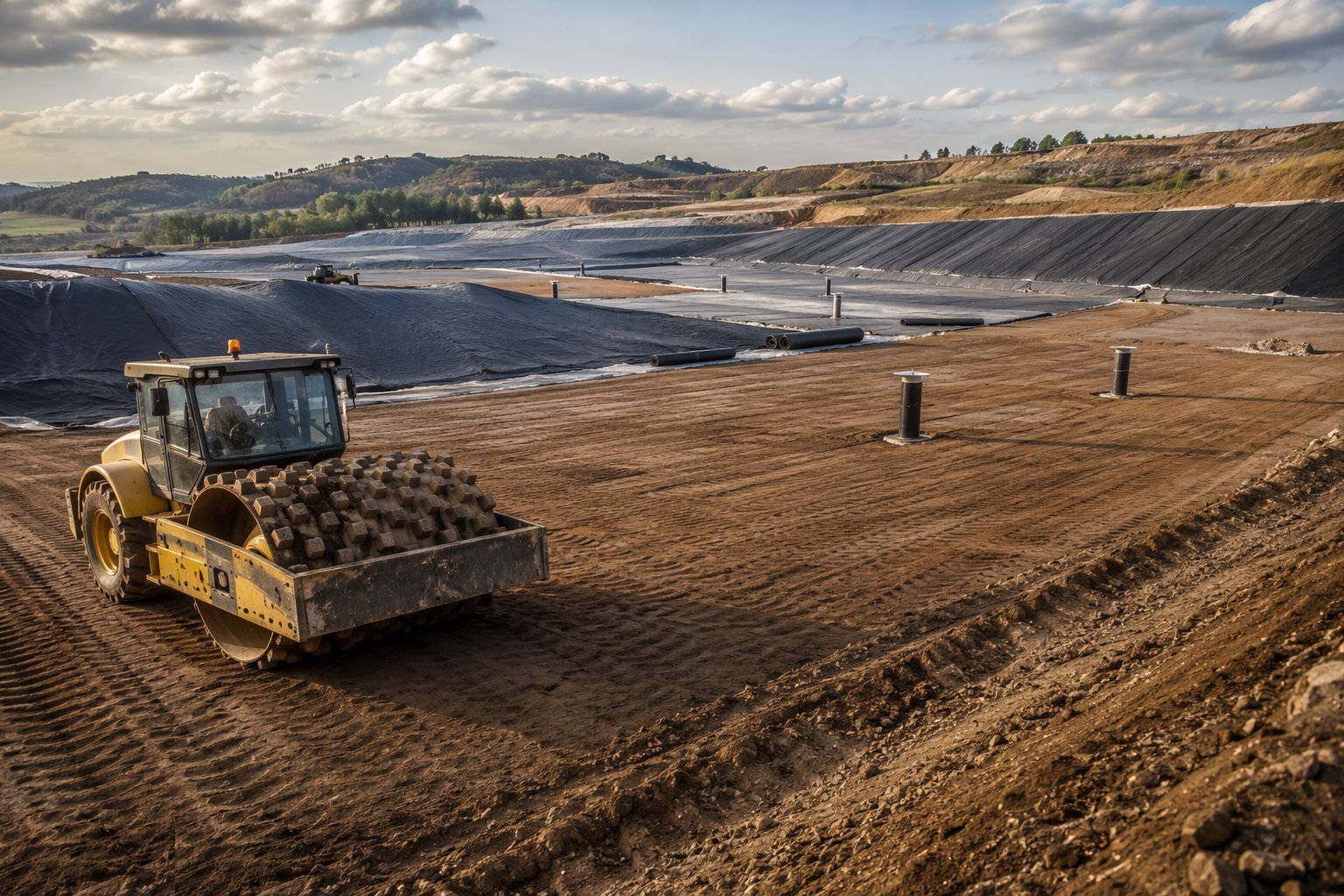
The clay liner is placed in lifts — typically 150–250 mm loose, compacted with padfoot rollers to the specified density and, critically, within the moisture window that lets the clay reach its design permeability of 1 × 10⁻⁹ m/s or better. Testing is continuous: moisture and density per lift, permeability verification on samples, and the surface protected from desiccation — a clay liner that dries and cracks before it is covered has failed before the membrane ever arrives. Where a geosynthetic clay liner substitutes for part of the clay, it is laid dry, overlapped per the manufacturer and covered the same day, because bentonite that hydrates early is bentonite wasted.
Step 3: Lay and weld the geomembrane
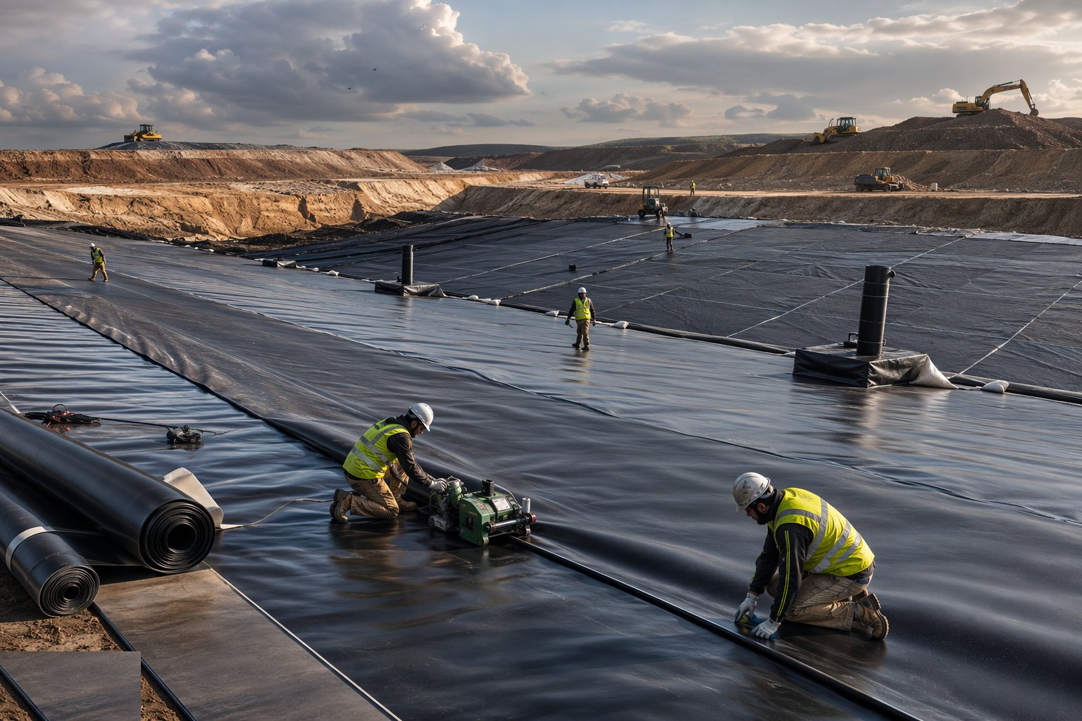
The HDPE membrane is deployed panel by panel on the accepted liner surface — no plant trafficking the membrane, panels shingled to shed water, and seams welded by twin hot-wedge machines with an air channel for testing, and extrusion welds for details and repairs. Every shift starts with test welds peeled and sheared to destruction; every production seam is logged by number, operator, machine and settings; and the entire installed surface is spark-tested or otherwise surveyed for pinholes before acceptance. The CQA engineer's signature closes each panel area, the protection fleece follows promptly, and the golden rule holds to the last square metre: nothing sharp, nothing heavy, nothing unrecorded touches this membrane ever again.
Step 4: Install the leachate collection system
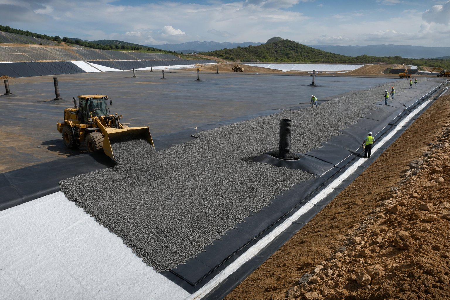
The drainage layer goes down over the protection fleece — graded stone placed carefully by machines working off the membrane, or geocomposite rolls — to the surveyed thickness, with perforated collection pipes bedded and laid to falls into the sumps. Sumps, risers and pumps are installed with their controls and level monitoring, and the whole system is proven: pipes jetted and surveyed, pumps wet-tested, flows traced. The first waste placement is then the most carefully managed operation on the site — a select protective layer of waste placed without plant ever bearing on the pipes — because a collection system crushed by the first compactor is a cell that drowns in its own leachate.
Step 5: Build the gas collection as the cell fills
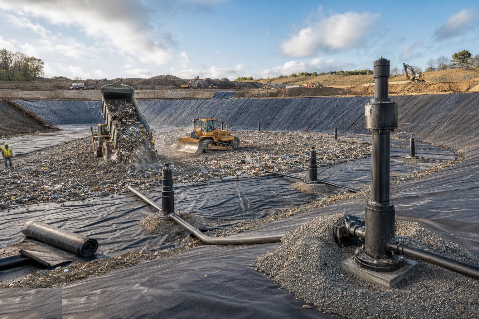
Gas infrastructure rises with the waste: vertical wells augered or built up in sections as filling progresses, horizontal collectors laid within the waste at design levels, and the header main run around the site with condensate knockouts at the low points. Everything is detailed for settlement — telescopic joints, slack in connections, anchors that allow movement — because the waste will compress by metres over the years and rigid pipework will shear. Wells connect to the header as zones come online, balancing valves tune the field, and the flare or engines at the compound take the gas: burned to carbon dioxide at minimum, generating power at best, but never vented raw.
Step 6: Cap the completed cells
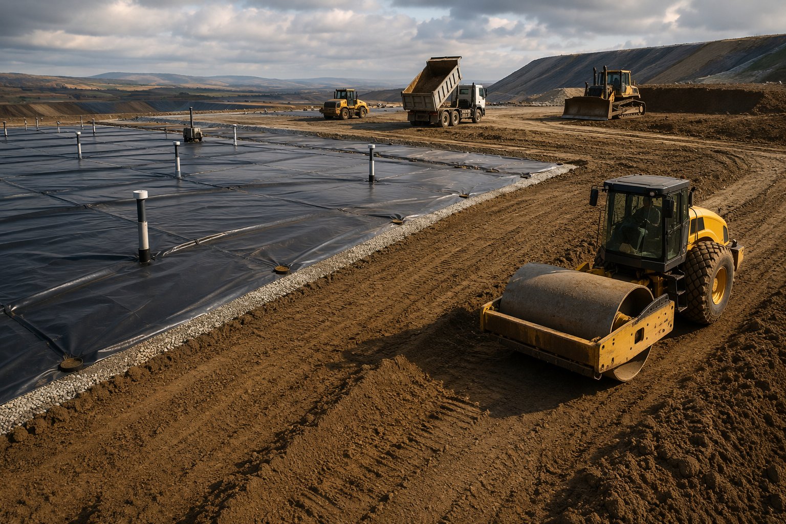
Capping starts with the regulation layer — fill graded over the waste to the restoration profile with the settlement allowance built in — then the barrier: a low-permeability layer of compacted clay or a capping geomembrane welded and tested with the same CQA discipline as the basal liner, tied into the gas collection layer beneath it so gas goes to the wells, not through the cap. Above the barrier, the drainage layer sheds infiltrating water to the perimeter, and restoration soils — subsoil then topsoil, placed without trafficking the drainage layer — build the growing medium. Every layer is surveyed as-built; the cap's gradients are the site's final defence against leachate generation, and ponding on a cap is a defect that rewrites leachate volumes.
Step 7: Restore and enter aftercare
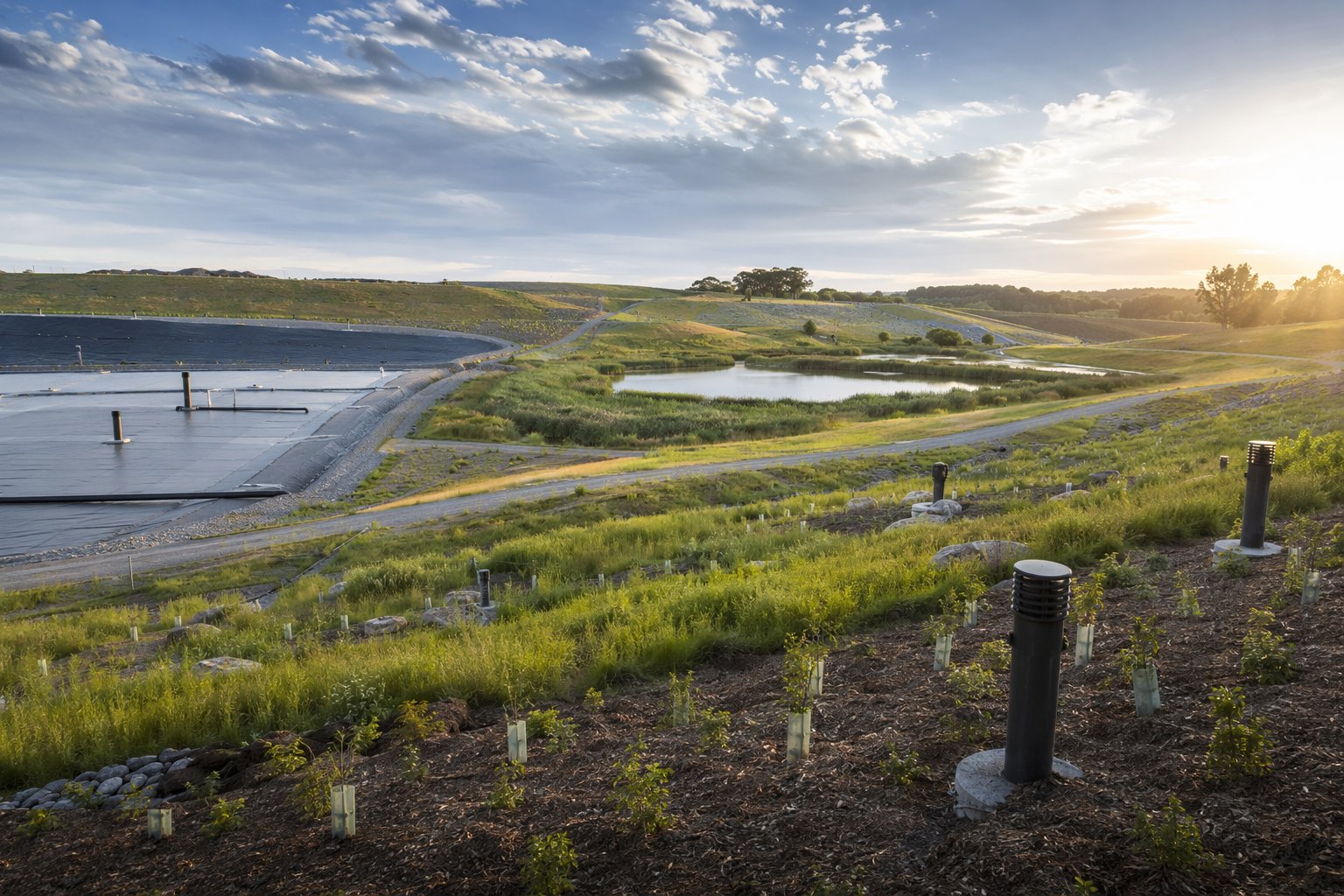
Restoration returns the landform to use: profiles blended to the surrounding landscape, soils spread and cultivated, seeding, planting and habitat features installed per the restoration plan, and fencing and access for the grazing or amenity after-use. Then the long tail begins — aftercare under the permit: leachate levels and quality monitored and managed, gas wells balanced and emissions checked, cap settlement surveyed and made good, drains jetted. The verification and monitoring records accumulate until the Environment Agency accepts the site is stable and surrenders the permit. It is the only construction job where success is a signature you may not live to collect — and the paperwork was the point all along.
Plant and equipment
- Excavators, articulated dump trucks and dozers with GPS machine control
- Padfoot and smooth-drum rollers for clay liner and fill compaction
- Hot-wedge and extrusion welding rigs with test-weld peel and shear kit
- Spark-testing and leak-survey equipment for geomembrane integrity
- Water bowsers for moisture control on clay placement
- Pipe lasers and jetting equipment for leachate pipework
- Gas well drilling rigs and fusion-welding kit for HDPE header mains
Quality control checks
- CQA plan governing every layer, with verification reports gating each acceptance stage
- Clay liner moisture, density and permeability testing per lift, plus desiccation protection checks
- Geomembrane test welds per shift, seam logs, destructive tests and full-surface spark testing
- Drainage layer thickness and stone grading surveys; leachate pipe falls verified by laser
- Gas well and header as-builts with settlement detailing recorded
- Cap as-built surveys per layer and restoration soil analysis before seeding
Safety considerations
- Plant and pedestrian segregation across wide earthworks: one-way systems, exclusion zones and positive communications
- Slope work and plant overturn risk on cell sides and caps: machine assessment and geofenced exclusion
- Landfill gas: methane monitoring, no hot work near wells, ATEX-rated equipment in gas zones, and confined-space rules in sumps and chambers
- Leachate contact as a biohazard: hygiene welfare, cover-cuts rules and vaccination advice for the workforce
- Dust, bioaerosols and odour on live sites: suppression, monitoring and welfare to match the exposure
- Lone working over large remote areas: check-in regimes and vehicle tracking
Common defects
- Clay liner desiccation cracking before covering — a failed barrier hidden under a perfect membrane
- Geomembrane punctures from stone, plant or trapped objects — found by the spark test, or found by the regulator years later
- Weld failures from contamination, weather or skipped test welds: seams that part under the first waste load
- Leachate pipes crushed at first waste placement — sumps dry, head rising, and no way back in
- Caps ponding after settlement: infiltration up, leachate volumes up, and the aftercare cost with them
- Gas wells sheared or drowned by settlement they were never detailed to survive
Best suited for
- Residual waste disposal where permitted void space is the asset
- Quarry and mineral-void restoration by landfilling
- Contaminated soil and stable hazardous waste containment cells
- Progressive capping programmes on operating and closing sites
How long does Landfill Engineering & Capping take?
Typical duration: A single cell takes 3–9 months to engineer, line and commission; capping campaigns run 2–6 months per phase; and aftercare under the permit extends for decades until surrender is accepted..