Waste Transfer Stations & MRFs
The sheds that sort society's rubbish — tipping halls with push walls, picking lines and trommels, and heavy-duty floors that take a daily beating — wrapped in odour, dust and fire controls under an environmental permit.
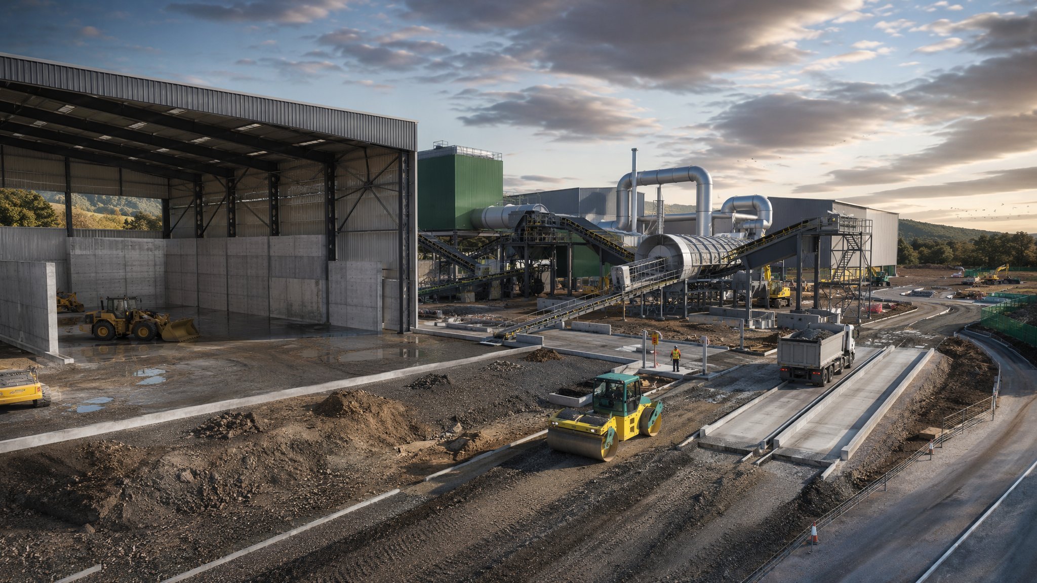
Last updated 2026-07-28 by the BuildPedia Editorial Team.
What is Waste Transfer Stations & MRFs?
A waste transfer station bulks waste for onward haulage; a materials recovery facility — an MRF — sorts mixed recyclables into saleable streams. Both are, at heart, big portal-frame sheds with a very hard-working interior: a tipping hall where collection vehicles discharge, push walls that loading shovels push waste against all day, storage bays, and a sorting line of trommels, screens, ballistic separators, magnets, eddy-current separators, optical sorters and picking stations that turns a mixed input into baled commodities. The whole operation runs under an environmental permit from the Environment Agency, and the permit — not the drawing — sets many of the rules: what waste can be stored, in what quantities, for how long, and with what fire, odour, dust and drainage controls.
The construction is defined by abuse. Floors are heavy-duty ground-bearing slabs designed along Concrete Society TR34 principles — thick reinforced concrete, dry-shake surface hardeners, armoured joints at every arris the telehandlers cross — because a waste floor is scraped, impacted and washed every working day of its life, and a floor that dusts and breaks up within a year is the classic under-specification story of the sector. Push walls are precast or in-situ reinforced concrete panels anchored to take repeated shovel impact, often steel-faced in the impact zone. Drainage is sealed and contained: everything that washes off a waste floor is contaminated and goes to foul sewer under consent or to tankered storage — never to surface water.
The environmental envelope is what separates a permitted facility from a bonfire in waiting. Odour control keeps the building under negative pressure with extracted air treated through biofilters or scrubbers, fast-acting doors that close behind every vehicle, and covered processing of the smelly streams. Dust is managed with misting cannons, extraction at transfer points and good housekeeping designed into the layout. And fire strategy is the sector's defining discipline: the Environment Agency's Fire Prevention Plan guidance governs maximum pile sizes, separation distances between stacks, quarantine areas for hot loads, detection — increasingly thermal imaging watching the waste surface around the clock — water supplies and access for the fire service. Build the shed beautifully and get the FPP wrong, and you do not have a waste facility; you have an incident waiting for a battery in the waste stream to start it.
When and why is Waste Transfer Stations & MRFs used?
Transfer stations and MRFs are built where waste logistics need them — at the edge of towns, on industrial land, beside the road network — and they are rising in number as recycling targets push more material through sorting infrastructure. They matter because they are the hinge between collection and treatment: close one and a city's waste goes nowhere. For the contractor, the critical conversations are durability and compliance: floors and push walls must survive the operating regime the operator actually runs, not the one in the brochure, and the permit conditions — fire plan, drainage containment, odour management — must be buildable and commissioned, because the Environment Agency inspects against them from day one of operation.
Types of Waste Transfer Stations & MRFs
Waste transfer stations
Bulking facilities where collection vehicles tip and waste is pushed, loaded and hauled onward in bulkers. The logistics hub of the system: hard floors, push walls, high doors and fast turnaround, with fire and odour controls proportionate to what sits in the bays.
Materials recovery facilities (MRFs)
Sorting plants for dry mixed recyclables: trommels, ballistic separators, screens, magnets, eddy-current units and near-infrared optical sorters feeding picking stations and balers. Process engineering in a shed — the civils exist to serve the line.
Household waste recycling centres
Civic amenity sites where the public tips into segregated containers, typically split-level with retaining walls the public side and container handling below. Public-facing civil engineering: traffic flow, fall protection, drainage containment and container-change logistics.
C&D and skip waste stations
Facilities taking construction, demolition and skip waste through picking, crushing and screening into recovered aggregates and residuals. The roughest duty in the sector — heavy inerts, crushers and screens shaking the ground they stand on.
Organics and food waste transfer
Enclosed reception and bulking for food and green waste heading to AD or composting. Odour-critical buildings: fully sealed, negative pressure, fast doors and biofiltration, because putrescible waste announces itself to the neighbourhood within hours.
Waste Transfer Stations & MRFs: step by step
Step 1: Earthworks and sealed drainage for a dirty site
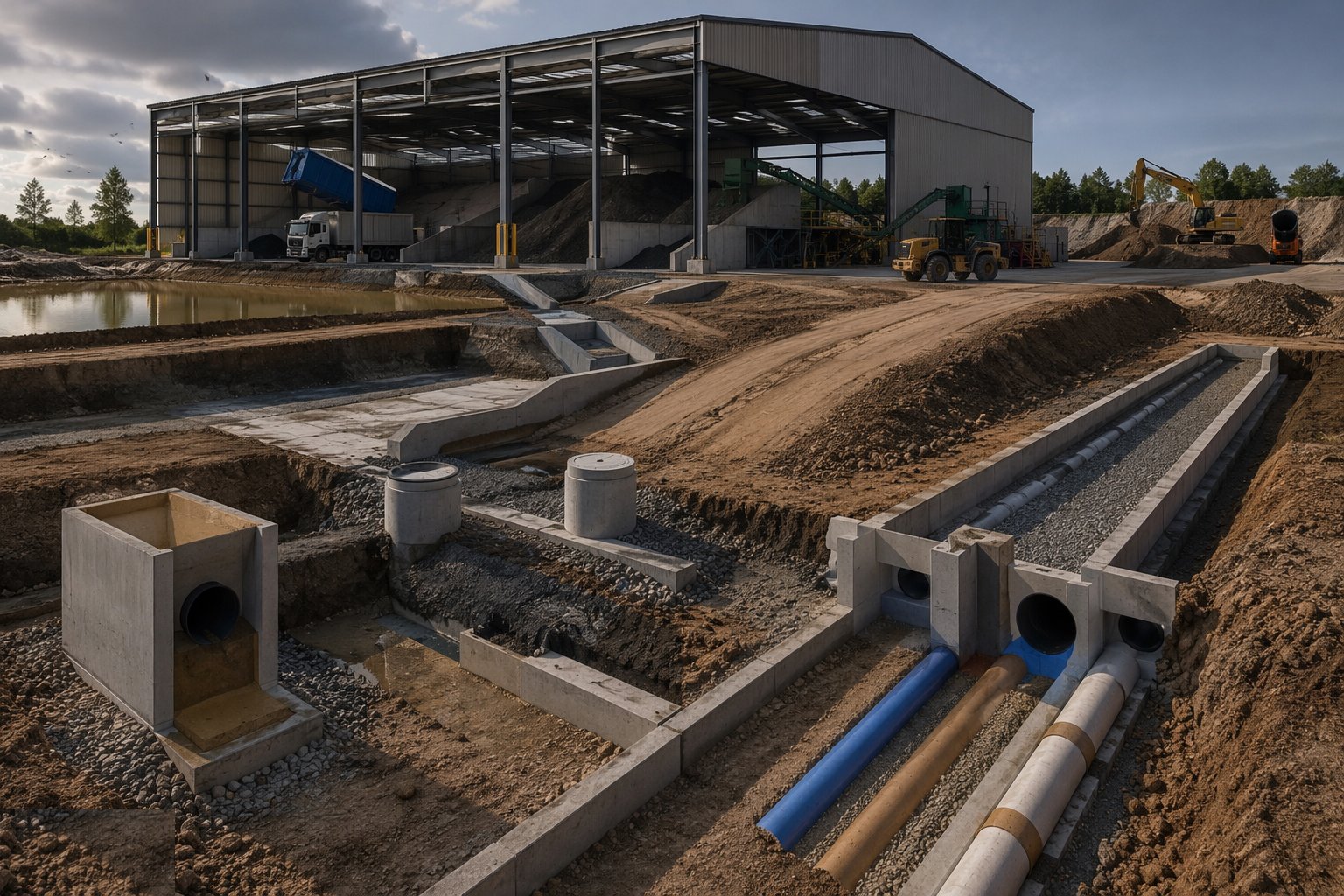
The site is set up as a contained system from day one: formation prepared and proof-rolled for the heavy slab, and a drainage design that splits clean and dirty water absolutely — clean roof water to surface drainage, everything that touches the waste area to a sealed system discharging to foul sewer under consent or to tankered storage with level alarms. The perimeter is graded so no contaminated runoff can escape the site boundary, and a wheel wash goes on the exit route. These are permit conditions cast in concrete: the Environment Agency will trace the drainage on its first visit, and a contaminated-water path to the surface system is an enforcement conversation, not a snag.
Step 2: Cast the heavy-duty floor slab
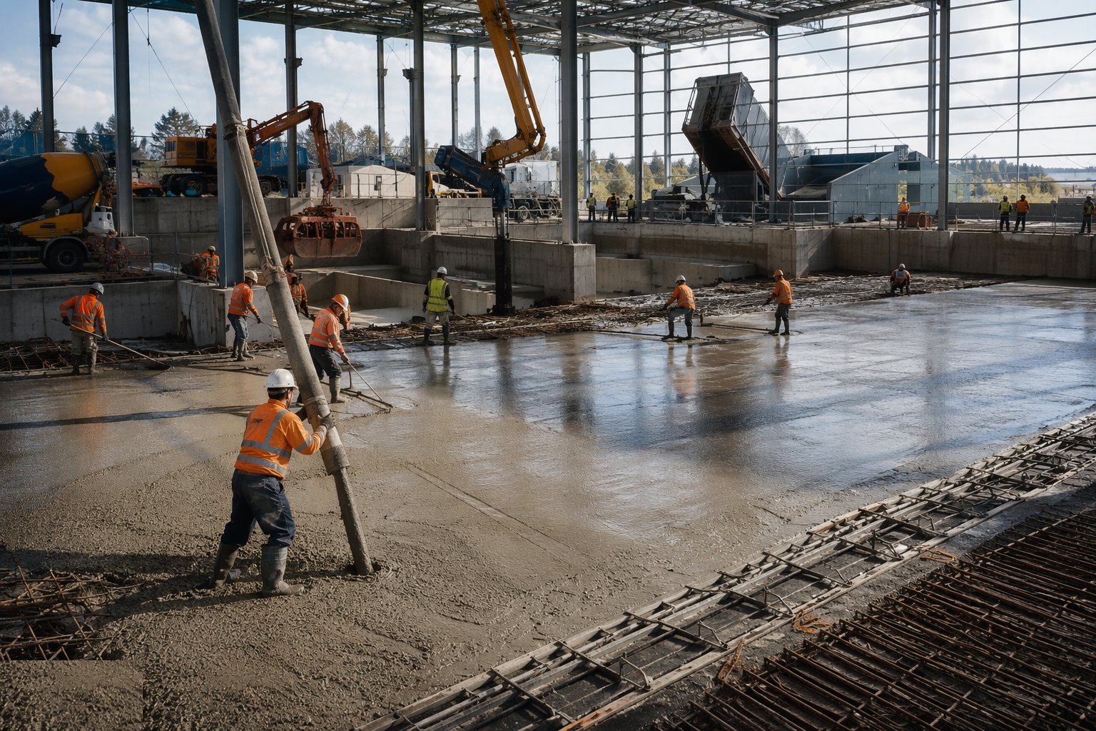
The floor is the facility's most-abused asset: reinforced ground-bearing slabs of 200 mm and up, laid in bays to a TR34-informed design with the surface regularity and levelness the operations need, dry-shake hardeners power-trowelled in for abrasion resistance, and armoured joints — steel angle or plate protection — at every free edge and joint the loading shovels cross. Impact and tipping zones get local thickening and, where the duty demands, steel plate facing. Curing is taken seriously because a surface that dusts from poor curing is a surface that will be potholed by year two, and saw-cut joints are made early and cleaned before the armouring seals them.
Step 3: Erect the portal frame and envelope
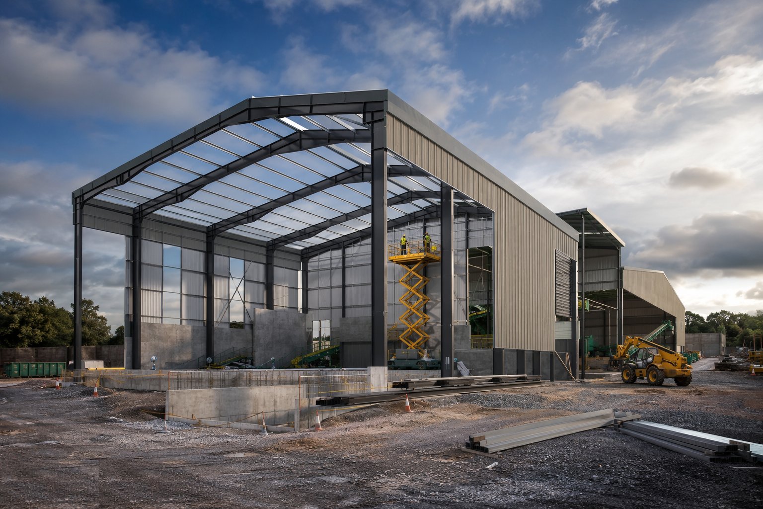
The frame goes up as conventional steel portal construction — high eaves for tipping and loading height, braced bays, crane beams where the process needs them — with cladding and doors detailed for the sector: large fast-acting doors on the vehicle routes, personnel doors with self-closers, bird-proofing at eaves and rooflights because flocks in the rafters are a hygiene and permit problem, and translucent panels kept clear of impact zones. Fire compartmentation and the structural fire protection follow the fire strategy, and the envelope is made closeable: odour control only works on a building that can be sealed and held under negative pressure.
Step 4: Build push walls, bays and heavy civils
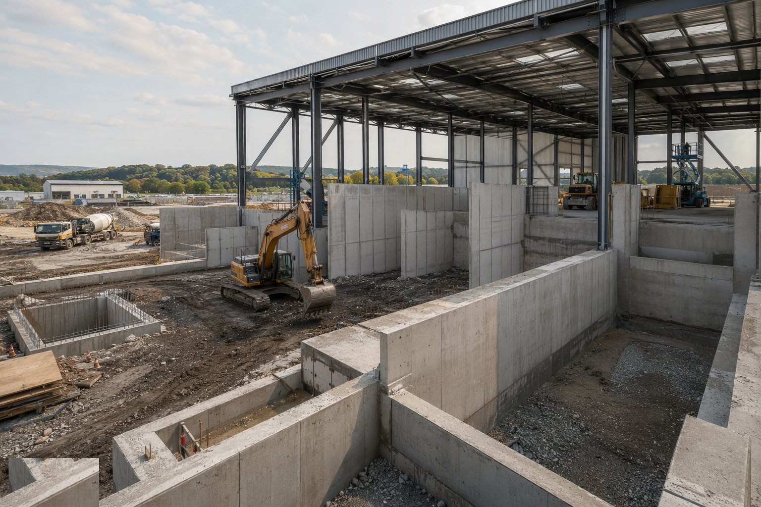
Push walls are precast concrete panels or in-situ walls anchored to the slab and their own foundations, set plumb and true because the shovel driver will find every weakness with the bucket edge — impact faces are steel-plated where the duty is heavy, and fixings are designed for reversal and replacement. Storage bays are laid out to the fire plan's pile-size and separation rules and marked permanently, the quarantine bay for hot loads is formed where the FPP puts it, and the sorting-line civils — conveyor pits, trommel foundations, picking-station mezzanine bases, baler plinths — are cast to the process vendor's loads and anchor drawings, surveyed, and signed over as interfaces.
Step 5: Install the sorting line and process equipment
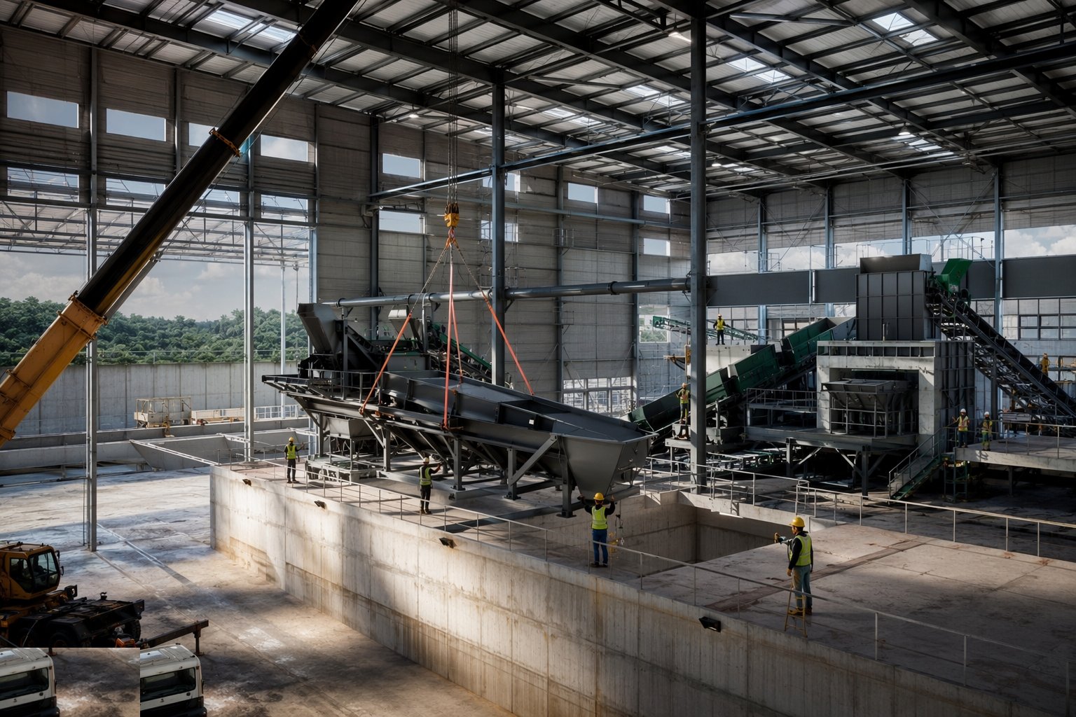
The process installation is mechanical erection inside a live civils project: conveyors aligned and levelled so belts track true, trommels and screens set on their plinths with vibration isolation as designed, ballistic separators, magnets and eddy-current units positioned to the line layout, optical sorters installed with their compressed air and lighting, and picking stations fitted with their drops, platforms and extraction. Guarding, emergency stops and pull-cords run the length of every conveyor because the line will be cleaned, cleared and maintained by people working next to moving machinery. Alignment records and the vendor's cold-commissioning checks close out each machine before the next depends on it.
Step 6: Fit odour, dust and fire systems
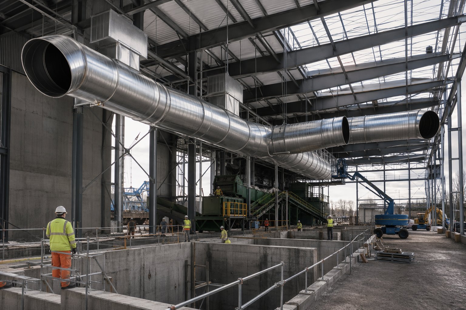
The environmental systems go in as engineered plant, not accessories: extraction ductwork sized to hold the hall under negative pressure, discharging through a biofilter bed or scrubber; misting lines and cannons over tipping and transfer points; and the fire strategy made physical — detection including thermal imaging cameras watching the waste surface, alarm and cause-and-effect panels, hydrants, monitors or sprinkler coverage as the FPP specifies, water storage sized to the required duration, fire service access routes kept and signed. Fast doors are commissioned to their open-close cycle times, because a door that stays up is an odour complaint and a negative-pressure failure in one.
Step 7: Commission against the permit
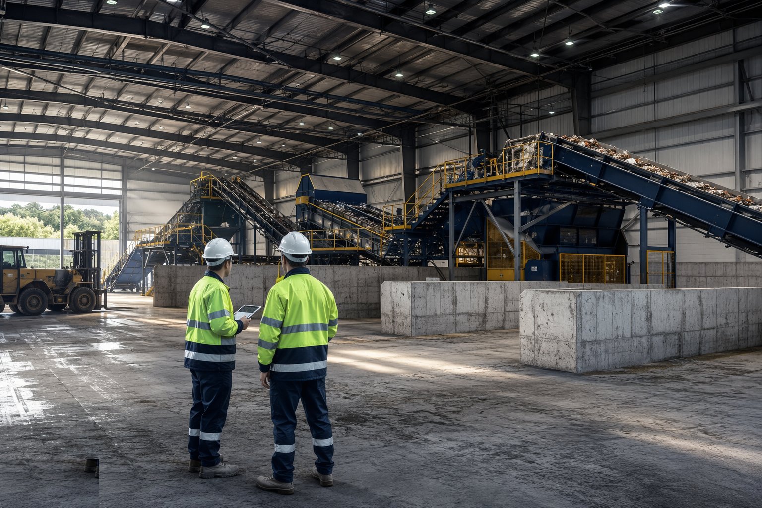
Commissioning runs cold then hot: conveyors and sorters proven empty, then on controlled material, then on the real waste stream with throughput, purity and availability measured against the vendor's guarantees. Odour systems are pressure-tested and smoke-checked; drainage containment is proven by test; and the Fire Prevention Plan is walked through with the operator — pile limits marked, quarantine procedures rehearsed, alarms witnessed. Handover includes the O&M manuals, the fire strategy documentation and the test records the permit will be inspected against, because from the first licensed tonne, compliance is the operator's daily business and the builder's lasting evidence.
Plant and equipment
- Concrete pumps, power trowels and dry-shake spreaders for heavy-duty floors
- Saws and armoured-joint installation gear for slab joints
- Crawler and mobile cranes for portal frame and process equipment erection
- MEWPs and telehandlers for cladding, ductwork and line installation
- Welding and fabrication kit for conveyor galleries and mezzanines
- Laser alignment equipment for conveyor and machine setting
- Commissioning instrumentation: pressure, flow and thermal imaging verification kit
Quality control checks
- Slab strength, thickness and surface regularity records per bay, with hardener coverage verified
- Push wall alignment, anchorage and impact-facing inspection before waste operations
- Drainage containment proven by test: sealed system integrity and alarm function
- Conveyor alignment and belt-tracking records; vendor cold-commissioning sign-offs per machine
- Odour system negative-pressure test across the hall with doors cycling
- Fire detection, alarm cause-and-effect and water-supply tests witnessed against the FPP
Safety considerations
- Heavy plant interface: telehandlers and loading shovels working near erectors during fit-out — segregation and exclusion zones enforced
- Silica and concrete dust on floor works: suppression, extraction and RPE through cutting and trowelling
- Work at height on frame, cladding and conveyor galleries: edge protection and MEWP discipline
- Stored energy on conveyors and process kit: isolation and lock-out procedures from the moment drives are connected
- Fire risk during construction: hot-work permits, and combustible waste kept out of the building until systems are live
- Biohazard hygiene on any brownfield waste site: welfare, washing and cover-cuts rules from day one
Common defects
- Floor surfaces dusting and breaking up within a year — under-specified hardener, poor curing, or joints left unarmoured
- Push walls cracked or displaced at their anchors by shovel impact the fixings were never rated for
- Fast doors damaged or defeated — left open, odour escapes and negative pressure is lost
- Conveyor pits flooding because the dirty-water drainage detail was value-engineered to a gully and a prayer
- Dust and odour extraction underpowered against the real throughput — designed to the brochure, operated to the tonnage
- Fire water storage or access short of the Fire Prevention Plan, found at the EA's first inspection
Best suited for
- Local authority and contractor waste logistics infrastructure
- Dry recyclables sorting for kerbside and commercial streams
- C&D recycling hubs feeding recovered aggregate markets
- Any operation where floor durability and permit compliance decide the business case
How long does Waste Transfer Stations & MRFs take?
Typical duration: A mid-size transfer station or MRF typically builds in 6–14 months including process installation and hot commissioning; heavy civils and floor programmes drive the critical path before the line arrives..