Sewage Pumping Stations & CSOs
The deep wet wells, pumps and overflow structures that keep flat networks moving — built watertight, commissioned against live flows, and expected to run unmanned for decades.
Last updated 2026-07-28 by the BuildPedia Editorial Team.
What is Sewage Pumping Stations & CSOs?
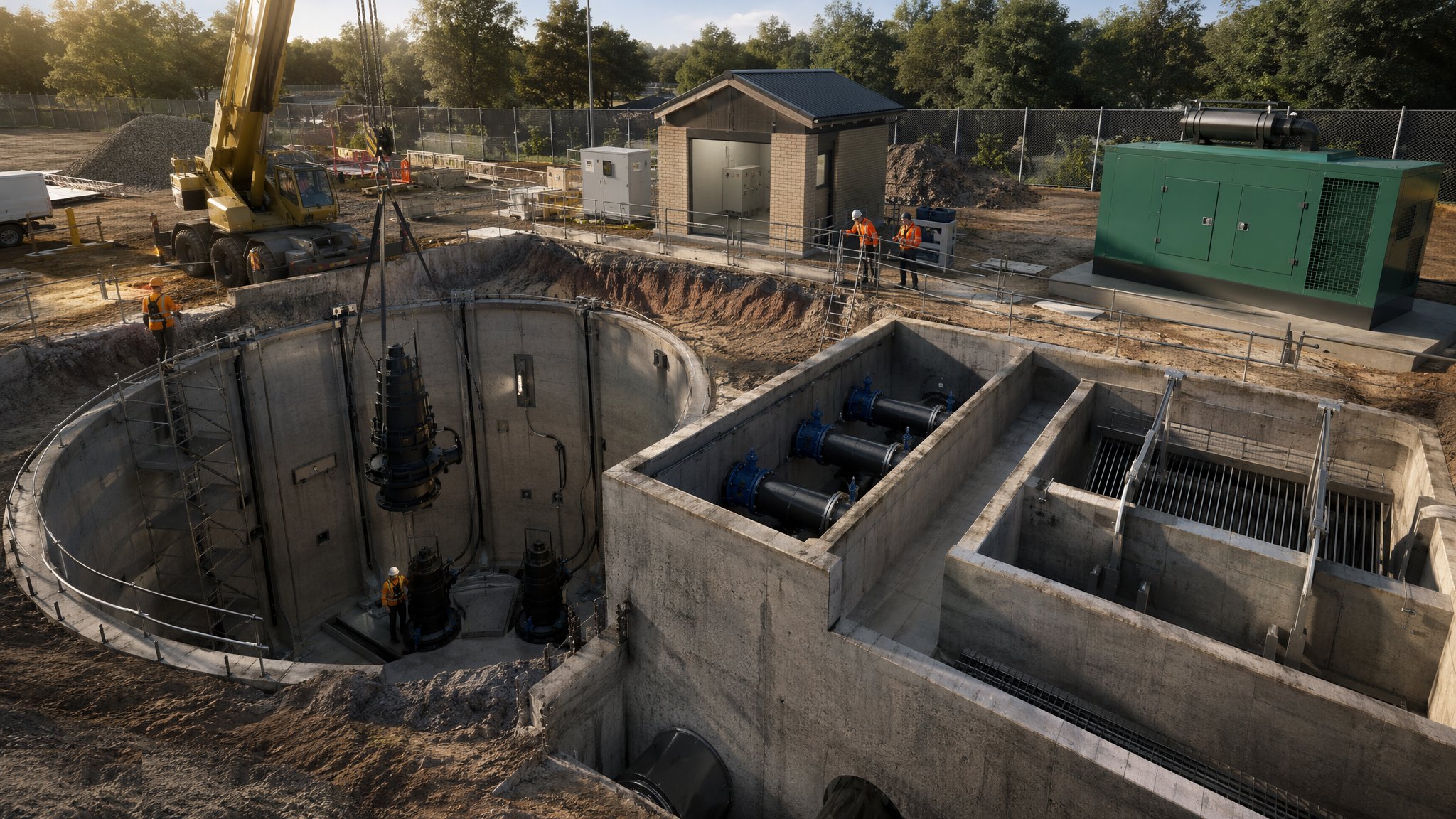
Where a catchment is too flat for gravity, the sewage is collected at low point and lifted. The pumping station is a deep wet well — typically 4 to 12 metres down, sized for storage and pump starts — with submersible sewage pumps on guide rails in the well, or dry-well pumps in a separate chamber alongside, discharging into a rising main that climbs back to gravity. Around the well go the inlet screens or grinder, the valve chamber with its non-return and isolation valves, the MCC kiosk with starters, level control and telemetry, and standby power — a generator or a dual supply — because the one thing a pumping station must never do is stop. In the UK these are built to the water company's adoptable standards where they will be adopted; in the UAE the municipal drainage authorities approve the design and inspect the construction as part of the network NOCs.
The construction game is a deep, watertight box in bad ground, usually in a live street or a corner of a live works. Wet wells are built as cast in situ water-retaining concrete to BS EN 1992-3, as segmental caisson shafts sunk to level, or as factory-made GRP package stations lowered into an excavated chamber and surrounded with concrete. The water table is usually part of the story — the well is the deepest structure on the development, often below groundwater, so dewatering, flotation checks on the empty shell, and watertightness testing all follow the deep-tank disciplines. Inside, the fit-out is precise: guide rails plumb so pumps drop and seat on their discharge elbows by their own weight, pipework supported and valved, level sensors set to the operating band, and the benching and falls in the well floor shaped to sweep solids to the pump suctions rather than let them settle and rag.
The cousins of the pumping station are the combined sewer overflow structures on older combined systems: chambers that pass dry-weather flow to treatment but spill storm flows to the watercourse through screens when the sewer surcharge demands it, increasingly with storm storage tanks that catch the first foul flush, and with Event Duration Monitors logging every spill because the regulators and the public now watch them. Building a CSO or storm tank means the same water-retaining concrete disciplines, plus penstocks, actuated gates, screens and the instrumentation that proves compliance. And the commissioning of any of these assets is done against live sewage — flows diverted, overpumped or tankered, pumps run on real duty points, level control proven through its full band, and the standby changeover tested by killing the mains and watching the generator pick up the load.
When and why is Sewage Pumping Stations & CSOs used?
Pumping stations are built where the topography says so: low-lying developments, coastal and flat catchments — half the Gulf's drainage is pumped for exactly this reason — and at the head of every rising main between gravity systems. CSOs and storm tanks are built or upgraded where combined systems spill too often, a regulatory driver that is reshaping the UK storm overflow estate. They matter because they are the highest-risk assets in a sewerage network: an unmanned station that fails in a storm floods properties within hours, and a CSO that spills wrong is a pollution incident with the operator's name on it. For the builder, the consequences sit in the details — a wet well that rags up because its benching is flat, a non-return valve that slams because the surge analysis was ignored, a level sensor set wrong so the pumps short-cycle themselves to death — and all of them surface at commissioning or in the first winter, in front of the adopting authority that has to live with your work.
Types of Sewage Pumping Stations & CSOs
Submersible wet-well stations
Pumps submerged in the well on guide rails, lifting out on chains for maintenance, with the valve chamber and MCC alongside. The modern default for foul pumping — compact, flood-tolerant and safe to maintain from the surface — with duty and standby pumps as a minimum and duty-assist on larger flows.
Dry-well stations
The pumps in a dry chamber beside or below the wet well, drawing from it through suction pipework. More structure to build and a confined space to maintain, but the pumps can be worked on in the dry — still favoured on larger terminal stations and where the operator's maintenance regime demands it.
Package GRP stations
Factory-built GRP wet wells with the pumps, pipework and valves pre-fitted, delivered to site and lowered into an excavation onto a concrete base, then surrounded with concrete. A week's civils instead of a month's — the quality battle is the flotation check, the concrete surround, and not twisting the shell as it is backfilled.
Combined sewer overflows and storm storage tanks
Overflow chambers with screens and penstocks that pass dry-weather flow onward and spill screened storm flow when capacity is exceeded, often backed by offline storm tanks that fill during the storm and pump back to treatment afterwards. Increasingly built with Event Duration Monitors and actuated control as spill performance becomes a regulated, published number.
Sewage Pumping Stations & CSOs: step by step
Step 1: Excavate and support the well formation
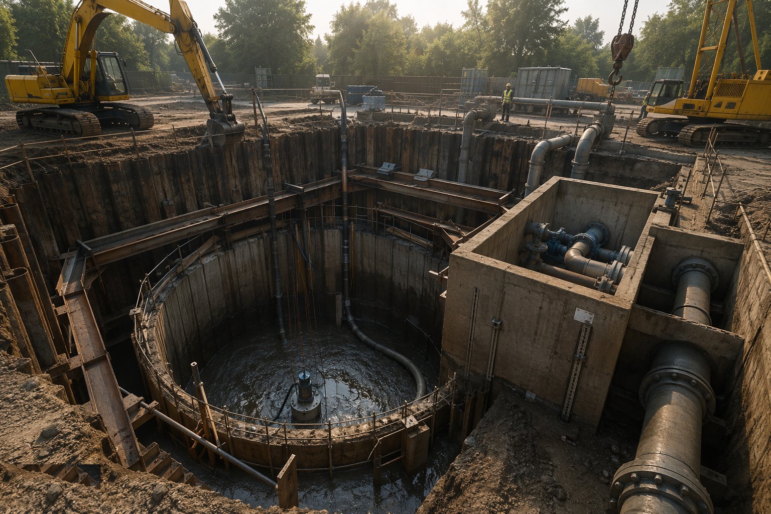
The wet well excavation is the deepest hole on most developments, in ground that is often wet — sheet-piled cofferdams, caisson sinking, or battered digs where there is room, with dewatering designed for the full construction period. Formation is proven, blinding cast, and the base goes down with its flotation detail — thickened base, extended raft, or holding-down piles where the water table demands it — because an empty wet well in wet ground is a boat hull, and more than one has floated, tilted and been dug out again at ruinous cost.
Step 2: Construct the wet well and chambers
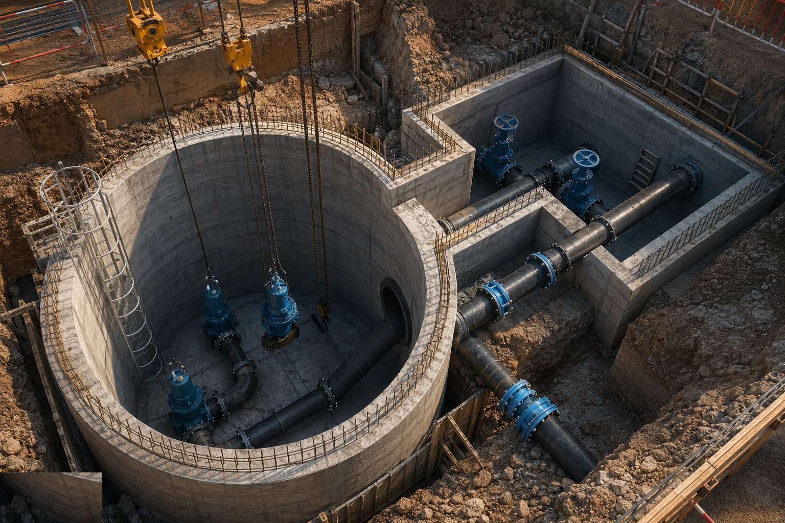
The well walls are cast in lifts as water-retaining concrete with waterstopped joints, or the precast/GRP shell is set plumb on the base and the surround concrete placed evenly all round — GRP shells filled with water as the surround rises so the buoyancy and pressure stay balanced. Benching and floor falls are formed to the pump suctions, pipework penetrations cast in with puddle flanges, and the whole structure water-tested before backfill. Every penetration and joint in a below-ground sewage structure is a future leak or a future gas path; the drawings show puddle flanges and stops for a reason, and substitutions get made exactly once.
Step 3: Install pumps, rails and internal pipework
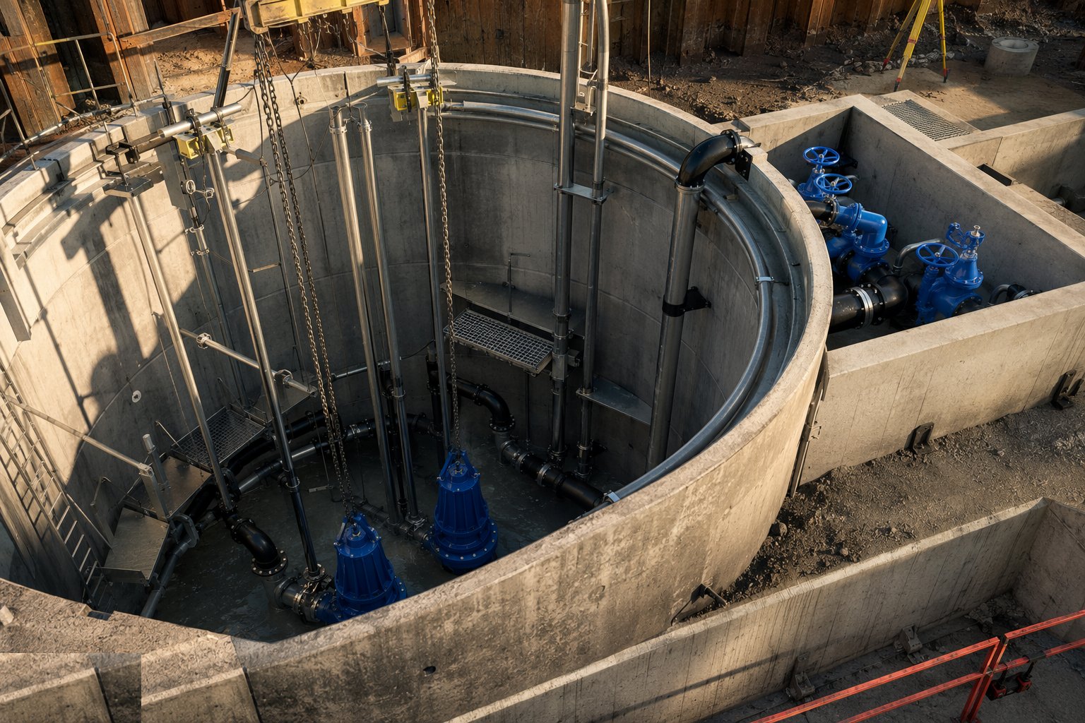
Guide rails are set plumb off the discharge elbows — a rail out of line is a pump that will not seat, leaking discharge pressure back into the well and tearing itself to pieces against the elbow. Pumps are lowered and seated, discharge pipework installed with its non-return and isolation valves in the valve chamber, and lifting chains, access covers and davits fitted. The non-return valves are selected against the surge analysis for the rising main — a slamming valve on a long main hammers the pipework at every stop, and the fix after commissioning is a new valve regime, not an apology.
Step 4: Install screens, grit handling and the rising main interface
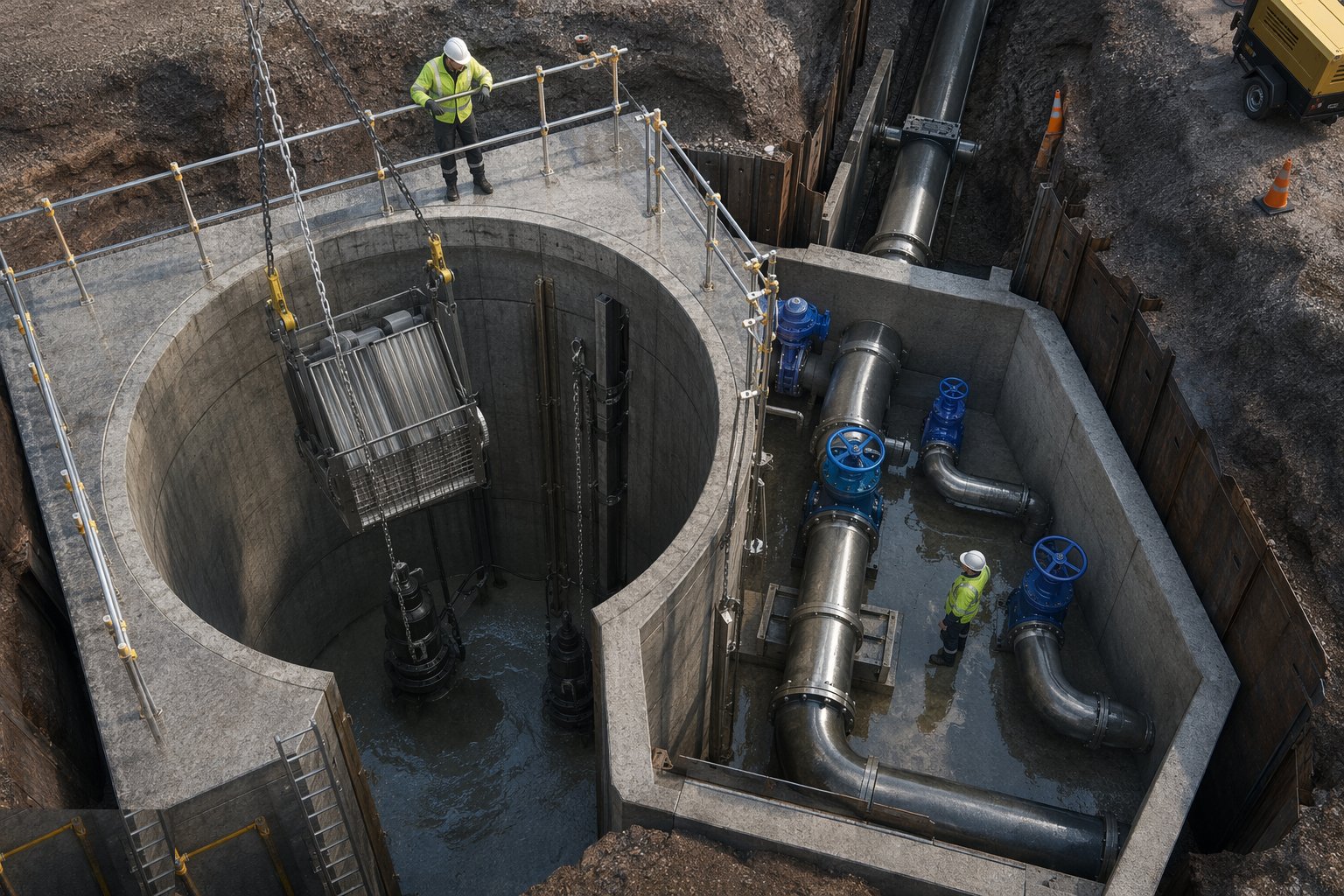
Where the design includes inlet screening, the screen and its screenings handling go in ahead of the well, with the bypass arrangements that let flows pass when the screen blinds in a storm. The rising main connection is made with its air valves at the high points and washout at the low, the surge vessels or soft-start regime matched to the analysis, and the discharge manhole built where the main returns to gravity. Air in a rising main is the silent flow-killer: an air valve omitted or wrongly sited shows up as pumps running against trapped air, delivering half their design flow at full power.
Step 5: Build the MCC, controls and standby power
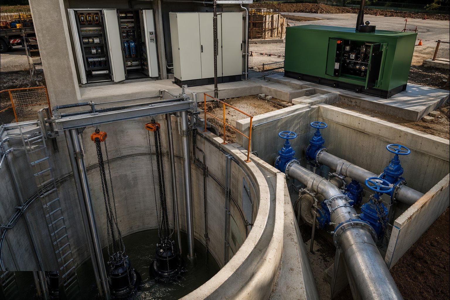
The motor control centre kiosk or building goes up with starters or variable speed drives, the level control system — ultrasonic or pressure transducers with float backups — set to the operating band, and the telemetry outstation wired to the operator's control room, because an unmanned station with no telemetry is an incident waiting for a quiet night. Standby generation is installed with its fuel system and automatic changeover, or the dual supply terminated, and the changeover is proven by test, not assumed. High-level alarm, pump fault, power fail — every signal that will one day wake an operator is tested end to end and witnessed.
Step 6: Commission against live flows
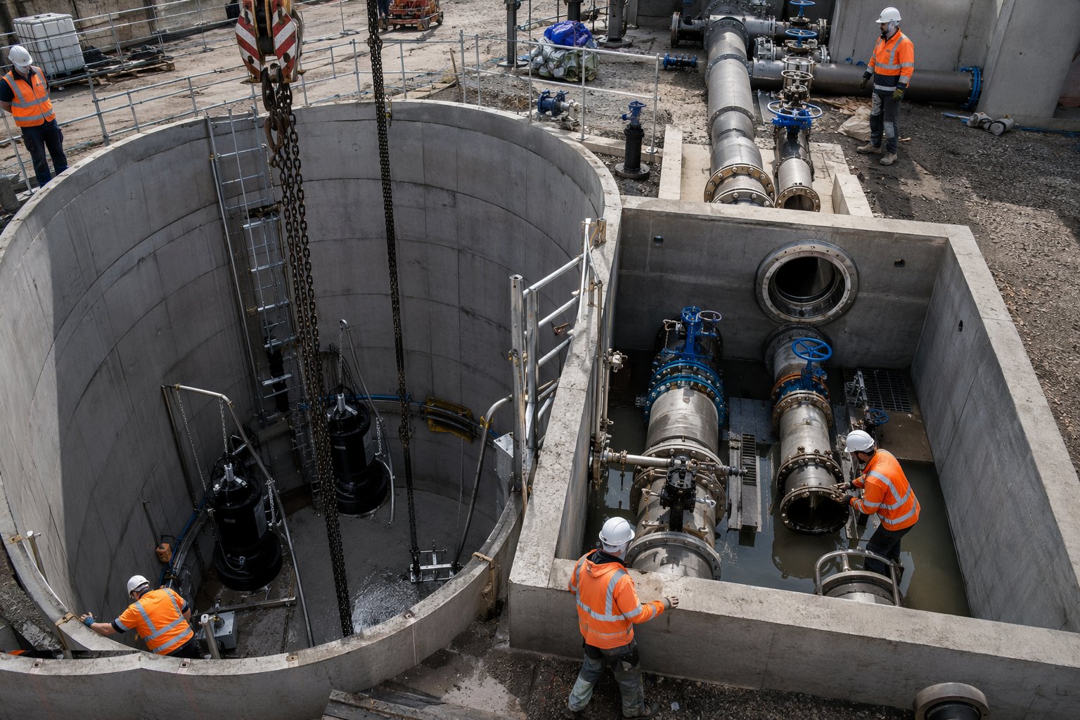
Commissioning a pumping station means running it on sewage: flows diverted or overpumped while the well is proved, pumps run across their duty points with flows and pressures logged, level control exercised through its full band, pump changeover and duty rotation checked, and the standby changeover proven by killing the mains supply under load. The rising main is filled, air purged through the valves, and discharge measured at the gravity manhole. Then the station is run as the operator will run it — unmanned, on telemetry, through storm and dry weather — until the adopting authority is satisfied, the O&M file is complete, and the asset is handed over to the people who will curse or bless it for the next forty years.
Plant and equipment
- Sheet piling rigs, caisson sinking equipment and cranes for the deep well excavation
- Dewatering plant: deep wells, wellpoints, settlement and discharge monitoring
- Concrete pumps and formwork for water-retaining construction; waterstops and puddle flanges
- Cranage and davits for pump and package station installation
- Overpumping sets — duty and standby — for diversions and commissioning
- Torque and alignment kit for guide rails, valves and rotating plant
- Electrical test and calibration equipment for MCC, instruments and telemetry loops
- Standby generator and automatic changeover panel, with load bank for witness testing
Quality control checks
- Water-retaining concrete records: cover, waterstop inspections, cube results, and the well water test certificate before backfill
- Flotation check signed off against the design water table before the empty well is left standing
- Guide rail and discharge elbow alignment survey; pump seating checks with witnessed drop tests
- Surge analysis compliance: non-return valve selection, air valve siting and soft-start settings recorded
- Level control set points, alarm and telemetry signals witness-tested end to end to the control room
- Standby changeover and full commissioning log — duty points, flows, pressures, run hours — in the handover file
Safety considerations
- Deep excavation beside live sewage: supported or piled sides, edge protection, controlled access down
- Confined space in wells and valve chambers — hydrogen sulphide is the killer here: permits, monitors, ventilation, top man and rescue
- Flotation and flooding of open excavations in wet ground, with overpumping diversions that must never fail unattended
- Lifting heavy pumps and covers over open wells — cranes, davits and chains inspected, exclusion below
- Sewage contact and biological hazard: hygiene regime, welfare with hot and cold water, Weil's disease briefing
- Electrical work beside water and wet steel: supplies isolated and tested dead, generators earthed, permits for live testing
Common defects
- Flat or wrongly benched well floors — solids settle, rags build, and the station needs vacuuming out every quarter
- Guide rails out of plumb or elbows out of level — pumps that will not seat and recirculate their own discharge
- Puddle flanges omitted or joints unwaterstopped — infiltration pumping the well round in circles
- Surge ignored: slamming non-return valves and air locks in the rising main cutting delivered flow
- Level sensors set wrong — pumps short-cycling, wells surcharging to the overflow, alarms crying wolf
- Standby changeover untested or telemetry unproven — the failure discovered in the first storm, at 2 a.m.
Best suited for
- Low-lying and flat developments where gravity drainage cannot reach the network
- Heads of rising mains transferring sewage between catchments
- Coastal and high-water-table sites where deep gravity sewers are uneconomic
- Storm overflow and CSO upgrades on combined systems facing spill performance regulation
How long does Sewage Pumping Stations & CSOs take?
Typical duration: A two-pump adoptable station with valve chamber and kiosk typically takes 12 to 20 weeks from excavation to commissioned handover; a package GRP station halves the civils programme, and a large terminal station or storm tank scheme runs to a year or more..