Wastewater Treatment Works Construction
The process civils that turn sewage into clean water — water-retaining concrete tanks, aeration lanes, settlement scrapers, digesters and odour plant — built to hold water before they ever treat it.
Last updated 2026-07-28 by the BuildPedia Editorial Team.
What is Wastewater Treatment Works Construction?
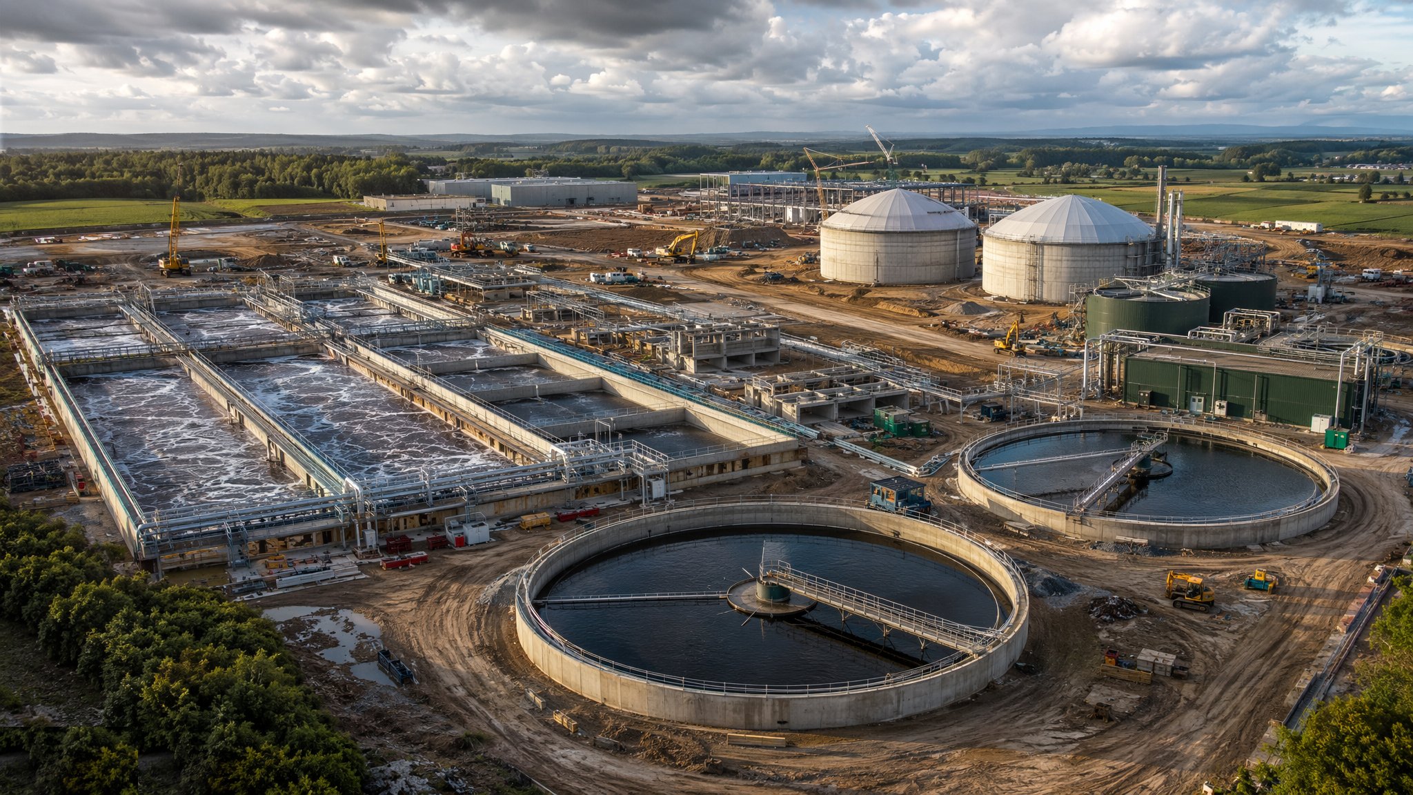
A treatment works is a concrete factory for biology. The process is a chain of tanks: incoming sewage is screened and de-gritted, settled in primary tanks to drop out the solids, driven through the activated sludge lanes where aeration feeds the bacteria that digest the dissolved load, settled again in final settlement tanks to separate the treated water from the biomass, and discharged to the watercourse within its consent. The sludge drawn off at each stage is thickened, digested — anaerobic digesters turning it to biogas that often runs the works' own combined heat and power engines — and dewatered for disposal. The contractor's job is to build the concrete, steel and mechanical plant that biology will live in, and to build it watertight, because a tank that leaks sewage into the ground or groundwater into the process fails before commissioning begins.
The structural heart of the job is water-retaining concrete, designed to BS EN 1992-3 — the Eurocode successor to BS 8007 — with crack widths controlled to 0.2 mm, concrete placed in carefully sequenced wall and slab pours, PVC or hydrophilic waterstops at every joint, and kickers cast true or formed with the walls. The mix matters as much as the workmanship: low permeability, controlled cement content for thermal control on thick sections, and in the Gulf, sulphate-resisting binders and high durability against saline ground and aggressive sewage gases above the waterline — hydrogen sulphide attack on unprotected concrete is the classic works failure, eating the soffits of channels and chambers over a decade. Every tank is water-tested before backfill or equipment goes in: filled to top water level, left to absorb, then measured for level drop over the specified test period.
Around the tanks goes the mechanical and electrical installation: inlet screens and grit removal, half-bridge or full-bridge scrapers on the circular tanks, fine-bubble diffuser grids or mechanical aerators in the lanes, penstocks and actuated valves, the digester roofs and gas systems, and the odour control plant — covers over the smelly processes ducted to chemical scrubbers, biofilters or activated carbon — because a works that can be smelled from the nearest housing is a works that will spend its life under enforcement. Commissioning is biological as much as mechanical: the lanes are seeded with sludge from a working site, the bacteria are grown up over weeks against gradually increasing flow, and the works proves itself by hitting its discharge consent with real sewage, not by passing a pump test.
When and why is Wastewater Treatment Works Construction used?
Treatment works are built when an existing works hits its consent or capacity limit, when new development loads the network beyond it, or when tightening discharge standards — nutrient removal is the current driver in the UK — force a process upgrade. They matter because they are the licensed point where a town's sewage meets the environment: the Environment Agency consent, or the municipal authority's discharge conditions in the UAE, is a legal limit the works must hit every day of its life, and the concrete and plant the contractor builds is what makes that possible. For the civils contractor the stakes are durability and watertightness — the works will run continuously for forty years, much of its structure inaccessible beneath water and sludge, and a cracked tank wall or a leaking joint in a live works is a repair done in sewage, at ten times the price of doing it right during construction.
Types of Wastewater Treatment Works Construction
Primary and final settlement tanks
Circular concrete tanks with sloped floors, central feedwells and rotating half-bridge or full-bridge scrapers sweeping sludge to the hopper and scum to the scum box. Precision civils: the weir level around the whole rim must be dead level, because a few millimetres of tilt shows immediately as a one-sided overflow.
Activated sludge aeration lanes
Long concrete lanes, often passivated (operated in series), with fine-bubble diffuser grids fed from a blower house, or surface aerators on older works. The biggest concrete pours on the site — deep walls, multiple cells, waterstops by the kilometre — and the diffusers and pipework are set to tight level tolerances so every membrane gets equal air.
Anaerobic digesters and sludge treatment
Sealed, insulated tanks — egg-shaped or cylindrical — heating and mixing primary and surplus sludge to generate methane, with gas holders, gas safety systems and CHP engines alongside. Gas-tightness replaces watertightness as the test that matters, and the welding, coatings and pressure testing are to pressure-plant standards, not drainage standards.
Odour control and venting plant
Covers over screens, channels and sludge processes, extracting foul air to chemical scrubbers, biofilters or activated carbon vessels before discharge through a stack. A process plant in its own right — ductwork, fans, dosing systems — built because the planning consent and the neighbours demand it.
Package and small works
Factory-built steel or GRP treatment units for small communities and remote sites — rotating biological contactors, submerged aerated filters, package activated sludge plants — craned onto a concrete slab and connected. A week of civils and a commissioning problem rather than a year of concrete, and the quality battle moves from the tank construction to the drainage and the desludging access.
Wastewater Treatment Works Construction: step by step
Step 1: Earthworks, drainage and foundations for the tanks
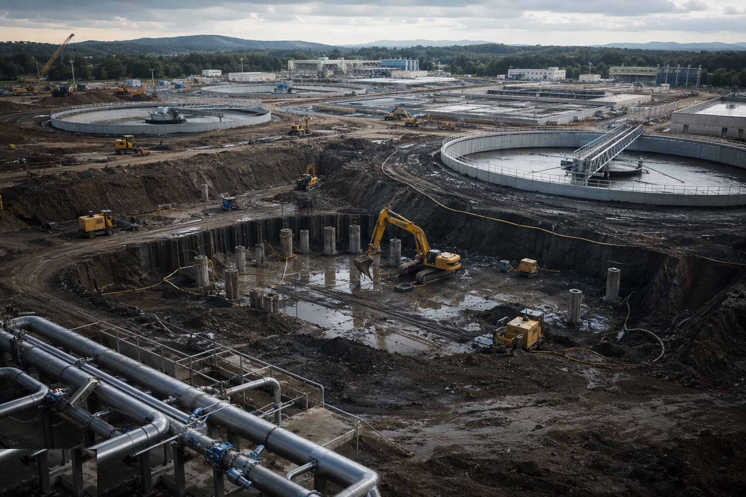
The tank formations are excavated to level — often below the water table on a riverside works, which means dewatering designed before digging and a flotation check on every empty tank for the rest of the job. Blinding is cast, the base reinforcement fixed to schedule with the specified cover, and the kicker either cast with the base or left as a formed starter with its waterstop. Base pours are large and thermal — on thick raft sections the mix is controlled for heat, cubes are taken per pour, and the joint positions follow the pour sequence drawing because in water-retaining work you do not get to choose where a construction joint lands on the day.
Step 2: Build the water-retaining structures
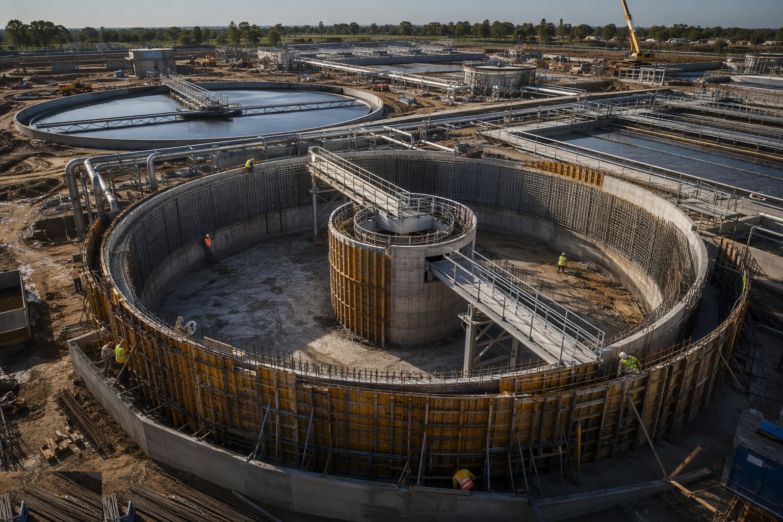
Walls go up in sequenced lifts to BS EN 1992-3 execution requirements: reinforcement fixed with the crack-control bar spacing the design assumes, formwork tight and clean, waterstops centred in the joints and protected until the next pour buries them — a kinked, displaced or burnt waterstop is a leak cast permanently into the wall. Concrete is placed in controlled layers, compacted without dragging the waterstop, and cured for the full specified period, because water-retaining concrete that dries out early cracks early. Channels, weirs and scum boards are formed to level — the final tank weir is checked with a water level or laser around the whole rim, and ground true before the tank is called complete.
Step 3: Water-test every tank
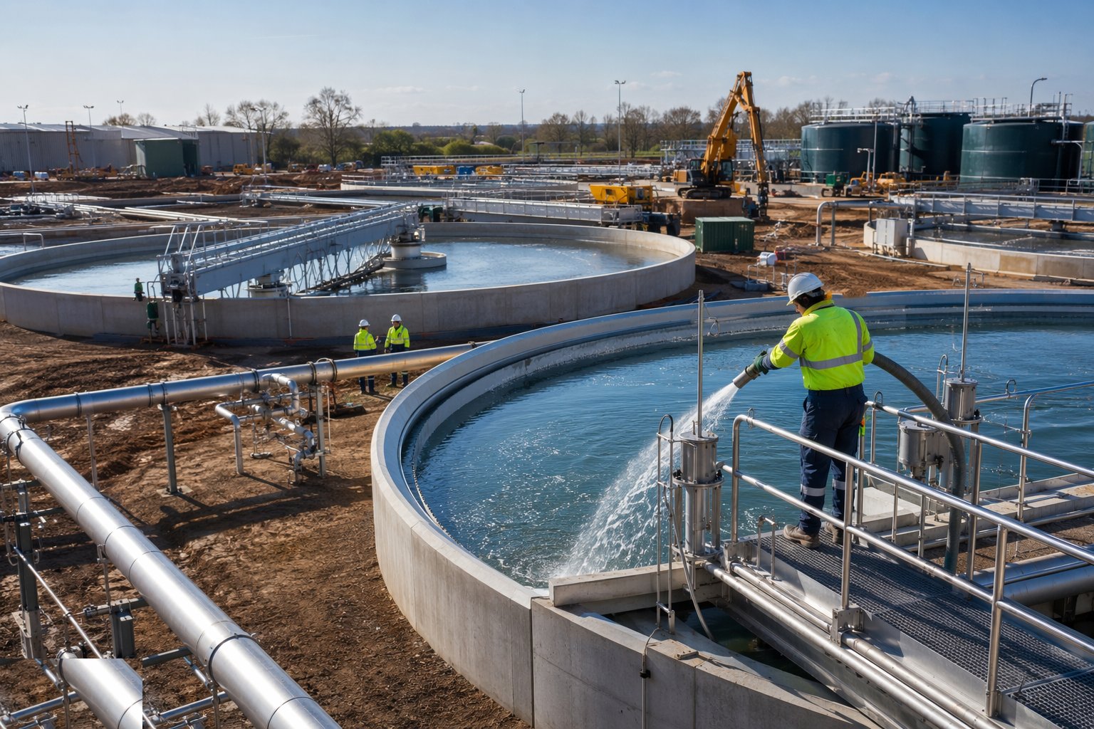
Before backfill, coatings or equipment, each tank is filled to top water level and left for the absorption period, then the level drop is measured over the specified test days against the acceptance criteria. Leaks show as damp patches, weeps at joints, or a measured drop beyond the limit — and they are repaired by injection or cut-out and recast, then retested, until the tank passes. This is the cheapest moment the leak will ever be found: the same defect found after the scraper is in and the tank is full of live sludge is a confined-space repair in sewage with the works running around it.
Step 4: Install the process mechanical plant
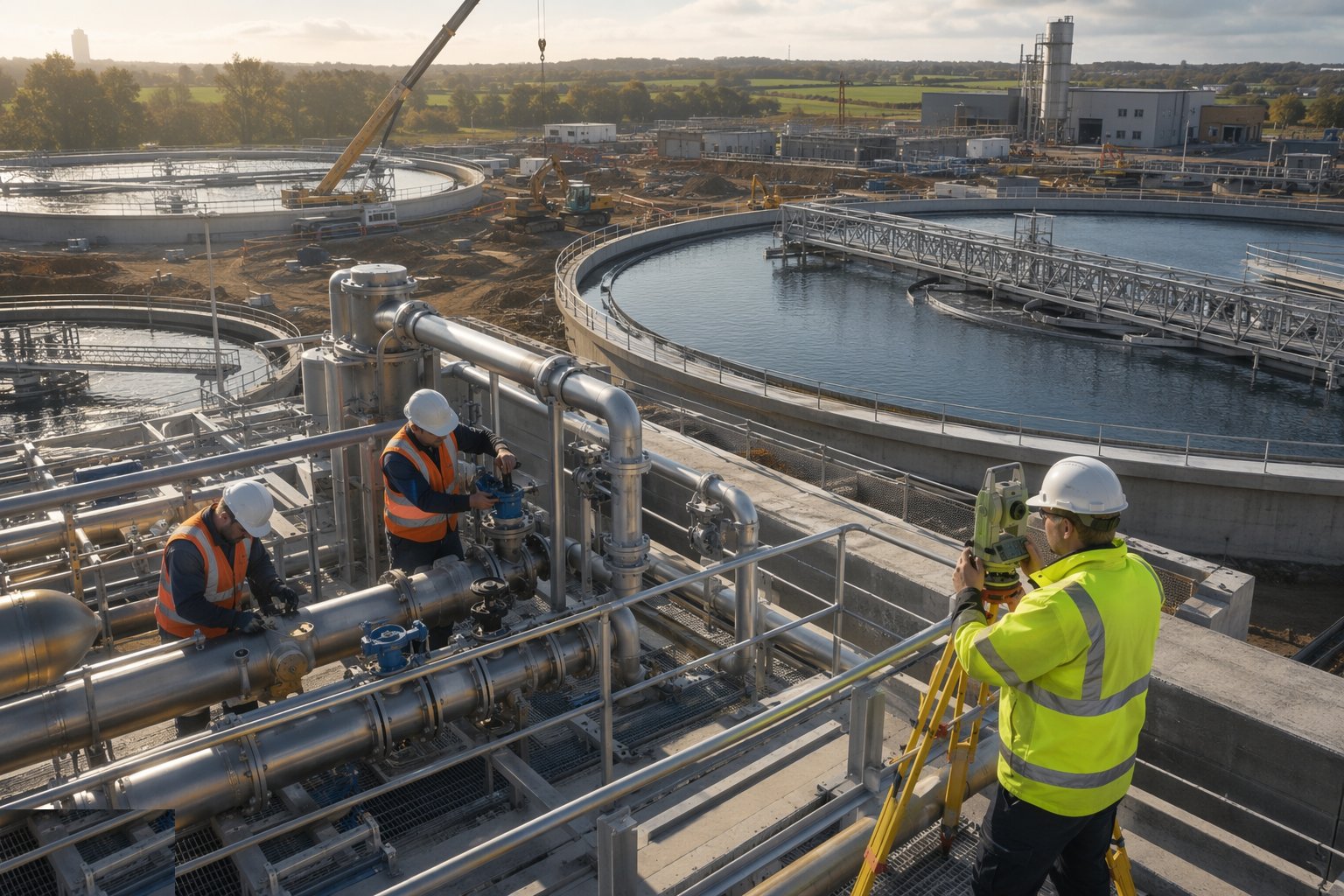
Scrapers are assembled on the tanks and set to the rim survey, diffuser grids levelled across the lane floors so air distributes evenly, penstocks and valves sealed into their frames, and the inter-process pipework — ductile iron, stainless, GRP and PE — installed, supported and pressure-tested. Alignment and level are everything: a scraper bridge out of level drags its blades, a diffuser grid out of level starves half the lane of air, and both defects masquerade as process problems at commissioning until someone puts a level on them. Every drive is run and rotated, every actuator stroked, before wet commissioning begins.
Step 5: Build the sludge stream and digesters
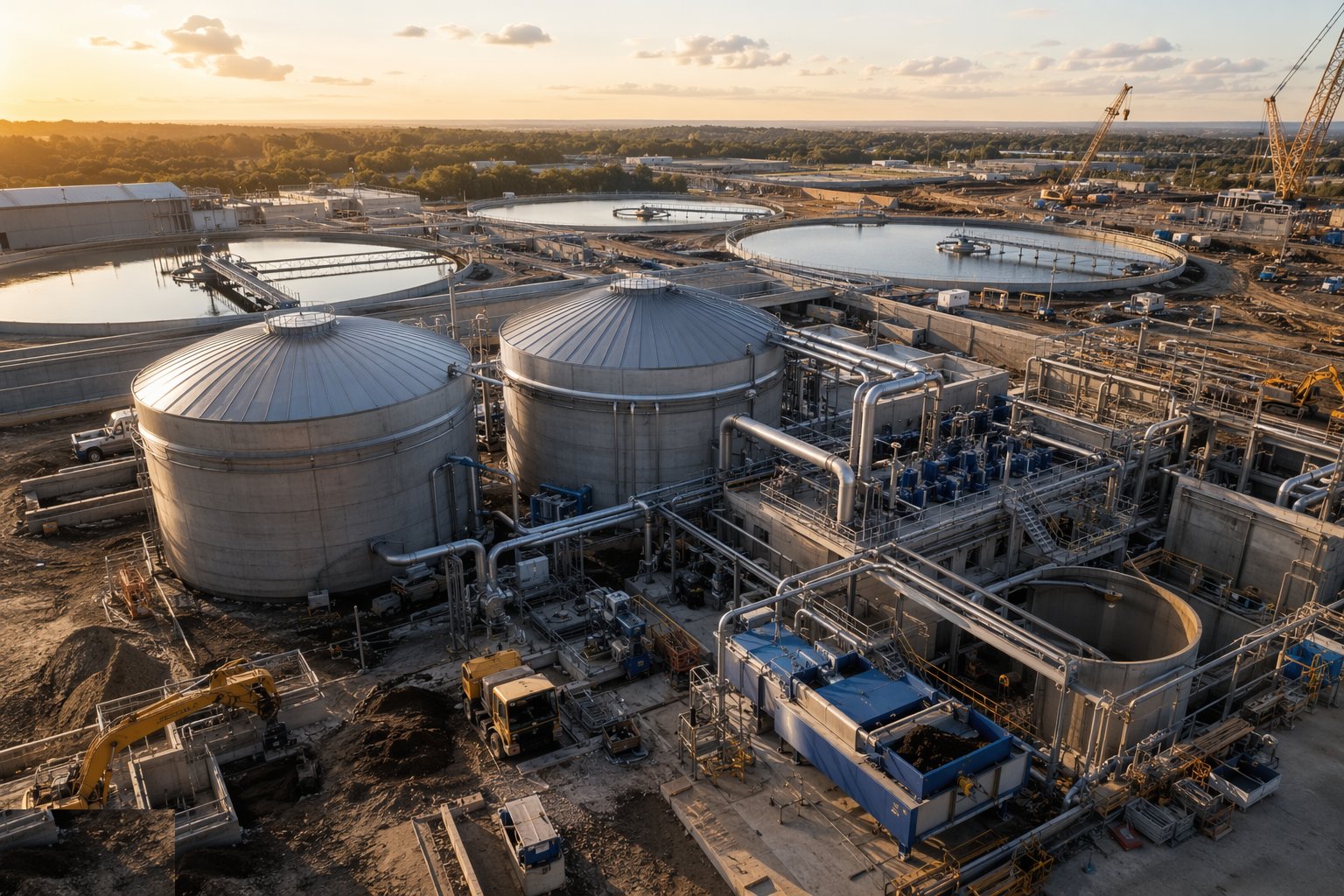
The sludge side runs in parallel: thickeners, digesters with their roofs, heating and mixing systems, gas pipework with its flame traps and safety devices, and the dewatering building. Digester construction is pressure work — steel or concrete vessels tested for gas tightness, gas systems installed and tested to the gas safety regime, and hot work around them controlled from day one because methane does not wait for commissioning to become a hazard. Coatings and linings go on to specification, holiday-tested where specified, because the inside of a digester is one of the most corrosive environments on any site.
Step 6: Install odour control and the M&E backbone
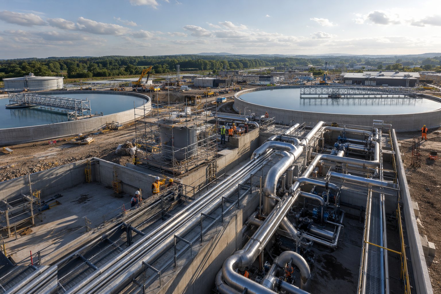
Covers and ducts are sealed over the odorous processes, the scrubber or biofilter erected with its fans, dosing and monitoring, and the stack set to its consent height. Around it goes the electrical backbone: the MCC building, standby generation or dual supplies, instrumentation — level, flow, dissolved oxygen, ammonia — and the telemetry that lets the water company watch the works from its control room. A treatment works is an unmanned site most of its life; the instruments are its eyes, and they are installed, calibrated and witnessed like it.
Step 7: Commission with water, then with sewage
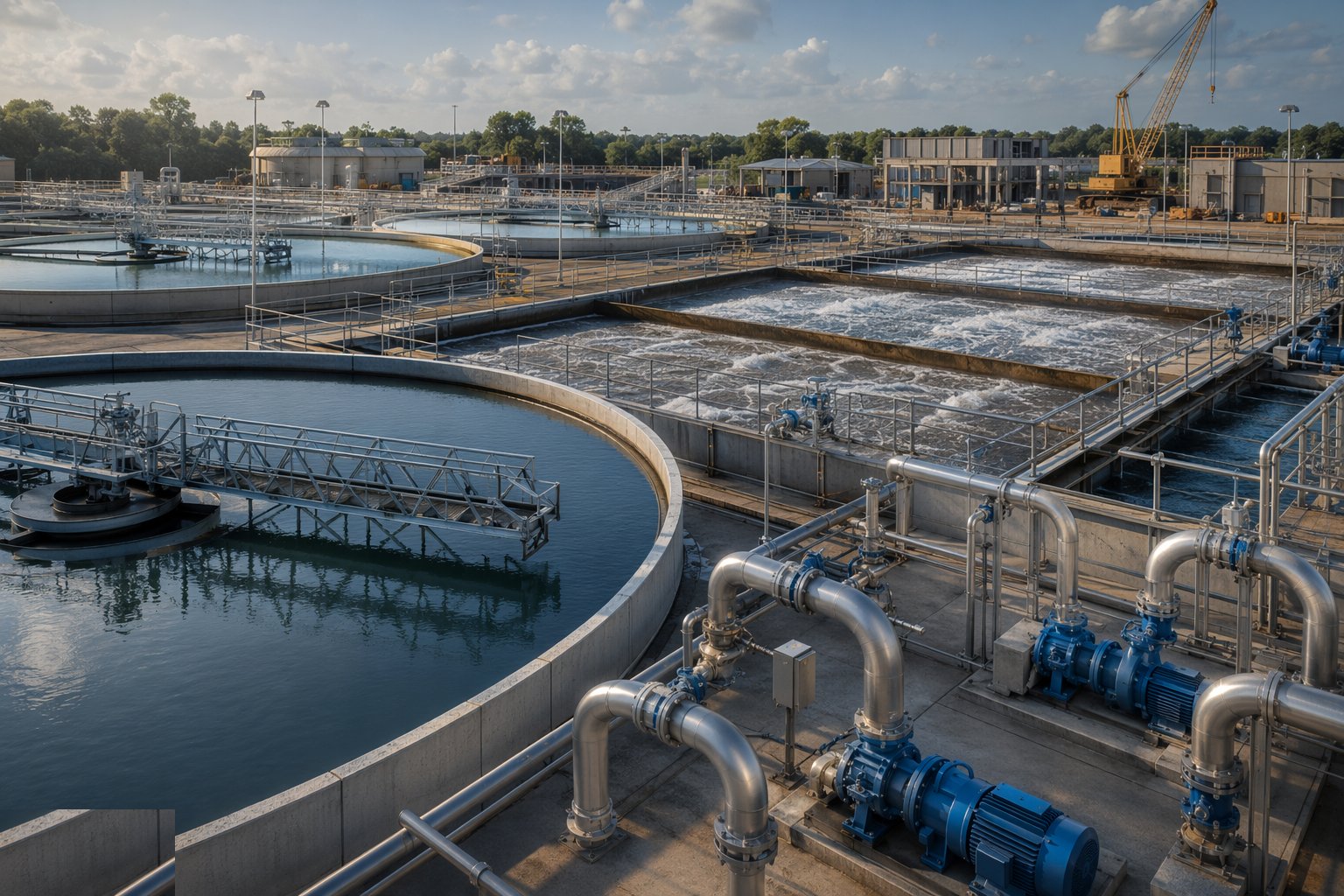
Commissioning runs in two gears. Clean water commissioning proves the hydraulics: tanks filled, pumps and scrapers run, flows balanced cell to cell, instruments checked against known levels. Then the works goes biological — the lanes are seeded with sludge imported from a healthy works, sewage is introduced at reduced flow, and the biomass is grown up over weeks while flows ramp to design. Performance is proven against the discharge consent over the specified demonstration period, with the process scientists driving and the contractor supporting — and only when the effluent quality holds does the works pass to operations with its O&M manuals, test certificates and as-builts.
Plant and equipment
- Crawler and mobile cranes for scraper bridges, digester roofs and MCC lifts
- Formwork systems for water-retaining walls — panel systems, soldiers and walers, kickerless systems where specified
- Concrete pumps and placing booms for sequenced tank pours
- Dewatering plant: deep wells or wellpoints, settlement tanks, discharge monitoring
- Water test kit: filling pumps, level gauges and dip tapes, temporary bulkheads for tank isolation
- Torque and alignment equipment for scraper and drive installation; laser levels for weir and diffuser surveys
- Welding and NDT equipment for steel digesters, gas pipework and pressure systems
- Cable pulling, instrumentation calibration and loop-checking kit for the M&E installation
Quality control checks
- Water-retaining concrete execution to BS EN 1992-3: cover, crack-control reinforcement, joint positions and waterstop installation inspected per pour
- Concrete cube and temperature records per pour; thermal control records on thick sections
- Water test certificates per tank — fill, absorption, measured drop, repairs and retest
- Weir, scraper and diffuser level surveys on completion of mechanical installation
- Gas tightness and pressure test records for digesters and gas systems; coating holiday-test records
- Instrument calibration certificates and loop checks witnessed before commissioning
Safety considerations
- Deep excavations beside live, operating processes — most works are built inside a working site with sewage flowing metres from the dig
- Confined spaces in tanks, channels and chambers: permits, ventilation, gas monitoring, rescue — hydrogen sulphide in a sludge tank is lethal at work height
- Flotation and flood risk: empty tanks below the water table, and riverside sites that flood
- Lifting over live plant: craneage near operational equipment under the operator's permit regime
- Biological hazards: sewage contact, Weil's disease, strict hygiene and welfare with hot and cold washing water
- Gas systems and hot work: methane zones, explosion-rated equipment, permits before a grinder comes out
Common defects
- Leaking joints and waterstop failures — displaced stops, honeycombed concrete against the stop, weeps found at water test
- Cracked walls from poor curing or thermal shock on thick sections — the 0.2 mm crack width exceeded before the tank sees water
- Out-of-level weirs and scraper tracks — one-sided flow and blades dragging at the first rotation
- Hydrogen sulphide attack on unprotected concrete above the waterline — soffits and chamber heads rotting within years
- Blocked or flooded diffuser grids from poor levelling and dirty air lines at commissioning
- Coating failures and pinholes in digesters and sludge pipework — corrosion starting at the holiday nobody found
Best suited for
- New municipal treatment works and capacity extensions on existing sites
- Consent-driven process upgrades — nutrient removal, tighter ammonia and solids limits
- Sludge treatment and digestion schemes with energy recovery
- Odour control retrofits where development has crept up to an old works
How long does Wastewater Treatment Works Construction take?
Typical duration: A medium municipal works extension — a pair of settlement tanks, an aeration lane and the associated M&E — runs 18 to 36 months from first dig to demonstrated performance, with water testing and biological commissioning alone taking the final quarter..