Utility Tunnels & Pipe Jacking
No-dig sewer and utility installation — microtunnels and pipe jacks driven between shafts to millimetre accuracy under roads, railways and rivers the city cannot afford to open.
Last updated 2026-07-28 by the BuildPedia Editorial Team.
What is Utility Tunnels & Pipe Jacking?
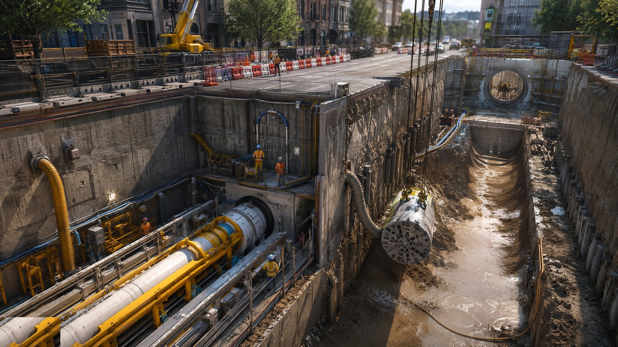
Open cut is a luxury. Under a live dual carriageway, a railway, a canal, or the congested streets of an old city, the sewer goes in without digging the surface: a tunnel boring machine or jacking rig drives from a launch shaft to a reception shaft, and the permanent pipe is jacked in behind it as the permanent lining — the pipe you install is the pipe the sewage flows through for the next hundred years. Small bores — roughly 300 mm to about 900 mm finished — go in by microtunnelling: a remote-controlled slurry machine, laser-guided, steering itself to the target while slurry carries the spoil back up the jacking pipes. Larger bores go by pipe jacking with an open shield or a full tunnelling machine big enough for a man to work in, the spoil mucked out and the pipes jacked in behind. Between the two sits guided auger boring: a pilot tube steered to line, then the auger and casing following it — the method of choice for short, accurate crossings under railways and roads.
The engineering lives in the shafts and the thrust. Launch and reception shafts are the biggest civils on the job — sheet-piled, segmental or caisson, sized to take the jacking frame, the thrust wall and the machine — because every tonne of jacking force pushes back against the launch shaft wall, and a thrust wall that deflects mid-drive is a drive that stalls. The machine is launched through a sealed entry in the shaft wall — a rubber seal holding back ground and groundwater — and driven to line and level by its steering rams against laser or gyro guidance, holding tolerances of tens of millimetres over drives that can run past 200 metres. Bentonite lubricant is pumped into the overcut around the pipe string to cut skin friction, interjack stations are built into the string on long drives to share the thrust, and when the machine breaks into the reception shaft the drive is surveyed, the annulus grouted, and the pipes become the sewer.
Pipe selection is a design decision with a site price tag. Reinforced concrete jacking pipes with steel collars are the UK default for bigger diameters; GRP jacking pipes — Hobas and Flowtite are the names everyone uses — dominate microtunnelling for their smooth skin, low jacking loads and corrosion resistance; vitrified clay jacking pipes go in where chemical resistance and longevity argue; and steel casings serve as sleeves for carrier pipes under railways and highways. The tolerances the whole game is judged by are line and level at breakthrough, joint integrity under test, and — the one nobody sees until it matters — settlement at the surface above the drive, monitored against trigger levels because an over-excavated drive under a live railway is an incident with a national audience. In the UAE, microtunnelling has become the standard for deep gravity corridors through the cities — the deep tunnel sewerage schemes in Dubai are exactly this game at scale.
When and why is Utility Tunnels & Pipe Jacking used?
Trenchless installation is chosen when open cut is impossible, unaffordable or politically dead: crossings under railways, motorways, watercourses and live services; deep gravity sewers where the trench would be a quarry; urban renewals where closing the street costs more than the tunnel. It matters because it is often the only technically credible route — and because it concentrates risk: in open cut, mistakes are visible and fixable, but in a 150-metre drive the pipe string is invisible, the machine is beyond reach, and a steering error, a collapsed face or a stalled drive is recovered at shaft-sinking prices, if it can be recovered at all. The method earns its cost where the surface cannot be touched; where the surface can be dug, honest open cut usually wins on price and always wins on forgiveness.
Types of Utility Tunnels & Pipe Jacking
Microtunnelling (slurry MTBM)
Remote-controlled slurry machines driving small bores with laser-guided steering, slurry separation at the surface, and GRP or clay jacking pipes installed as the permanent sewer. Untraceable accuracy — drives of 100–250 m between shafts holding line and level within tens of millimetres — and no man ever enters the bore.
Pipe jacking with manned shields
Larger diameters — from about 900 mm up — driven with an open shield, roadheader or full tunnel boring machine in front of a string of reinforced concrete jacking pipes, with interjack stations on long drives. Men work at the face, spoil travels out by skip or conveyor, and the machine is steered like a ship on rails.
Guided auger boring and pilot-tube methods
A steered pilot tube driven to line and level first, then augers and steel casing following it home — the standard short-crossing method under railways and highways, typically 30–80 m, where the bore is dry enough to auger and the casing carries the carrier pipe or ducts inside.
GRP and clay versus concrete jacking pipes
Not a drive method but a defining choice: GRP pipes for low friction, corrosion resistance and microtunnel compatibility; vitrified clay for chemical durability in aggressive sewers; reinforced concrete with steel collars for large-diameter economy. The pipe decides the jacking loads, the joint design and the life of the asset.
Utility Tunnels & Pipe Jacking: step by step
Step 1: Sink and equip the launch and reception shafts
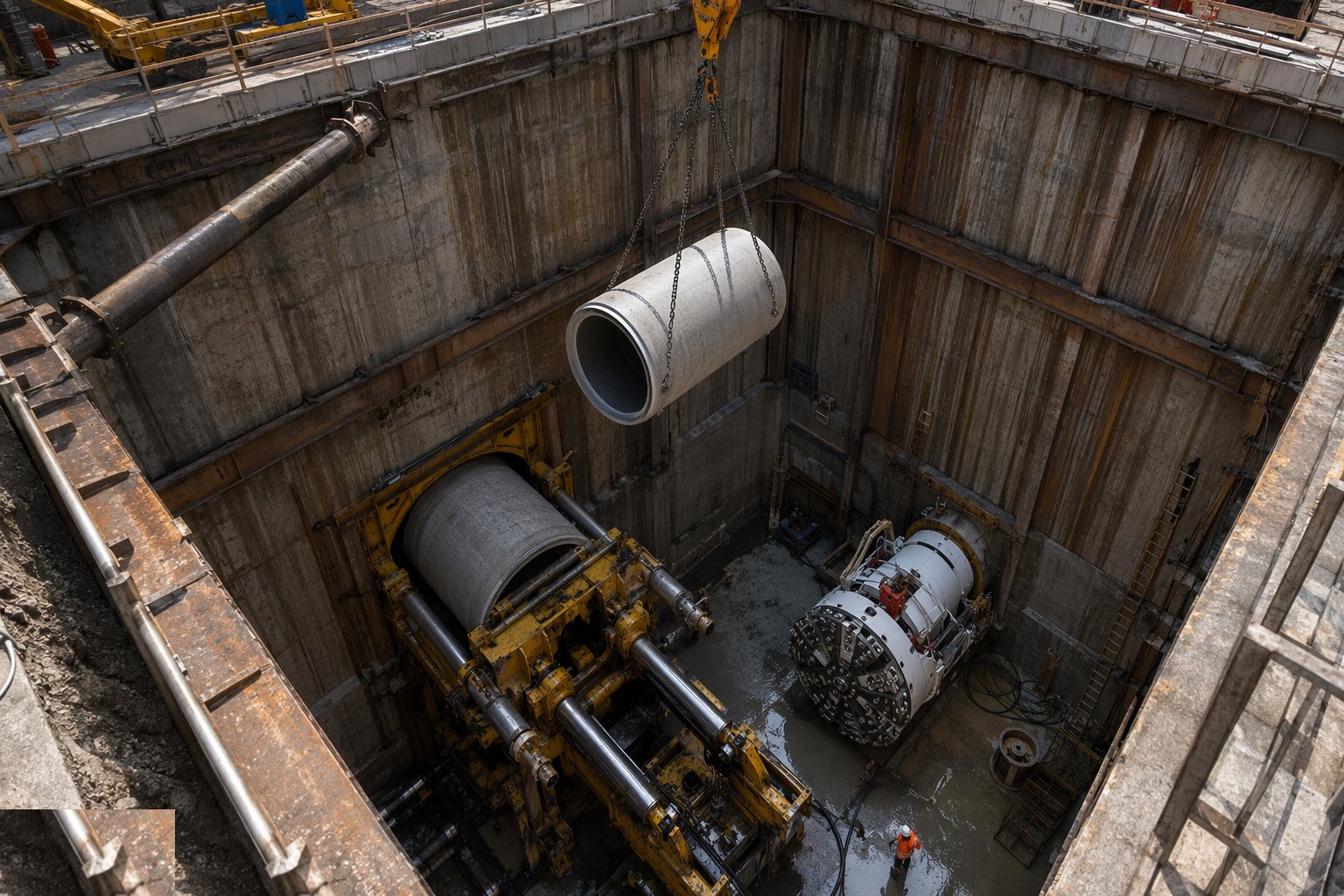
The shafts are the job's foundation: sheet-piled cofferdams, precast segmental rings, or caissons sunk to depth, sized for the machine, the jacking frame and the pipe lengths. In the launch shaft, the thrust wall is cast or packed to spread the full jacking load into the shaft wall — designed, not guessed, because the wall will feel hundreds of tonnes — and the jacking frame, guide rails and thrust ring are set exactly to the drive's line and gradient. The reception shaft gets its eye and its recovery arrangements. Every millimetre of error in the shaft set-up reappears at the face; you do not steer out of a launch that started wrong.
Step 2: Launch through the shaft eye
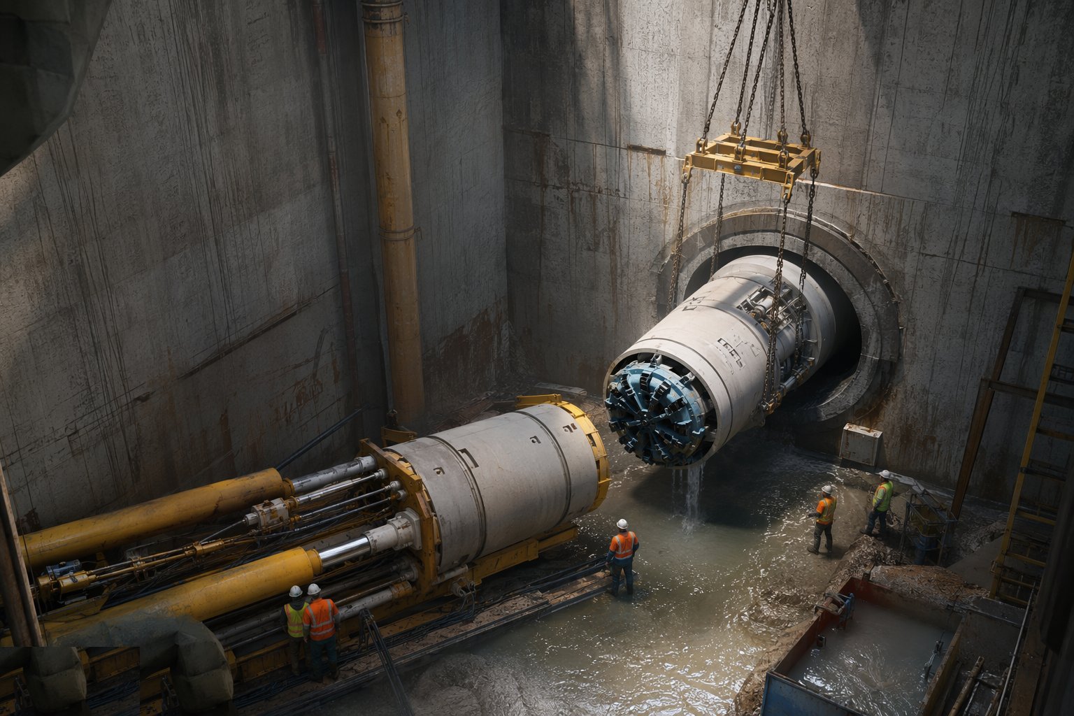
The machine is lowered in, connected to slurry, power, hydraulics and the guidance system, and pushed to the shaft eye — the sealed opening in the shaft wall with its rubber seal holding back the ground. Breaking through the eye is the first nervous moment: ground and groundwater test the seal, the face pressure is set against the ground, and the machine takes its first cut. If the ground needs treatment — grouting, dewatering, compressed air on big drives — it is in place and proven before the eye is opened, because an uncontrolled inflow at the eye is how shafts flood and drives end before they start.
Step 3: Drive, steer and monitor
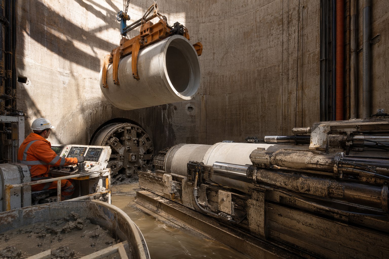
The drive settles into its rhythm: the machine cuts, slurry or skips carry spoil out, a pipe is lowered, jointed and home, the rams stroke, and the cycle repeats — with the guidance system tracking position continuously and the steering rams correcting millimetre by millimetre to hold line and level. Jacking loads are logged every stroke against the predicted curve: a load climbing beyond prediction is ground telling you something — a collapsed overcut, dry lubrication, an obstruction — and the good tunneller reads the load trace like a pulse. Settlement monitoring runs at the surface above the drive, checked against trigger levels, and face pressure and slurry returns are watched for over-excavation.
Step 4: Lubricate the string and share the thrust
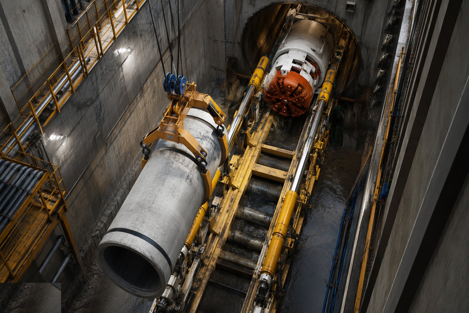
Bentonite lubricant is pumped through injection ports into the annulus around the pipe string as the drive advances, cutting skin friction — on a long drive, lubrication is the difference between jacking loads the wall can take and loads that stop the job. Where friction still climbs, interjack stations are built into the string: jacking cylinders between pipes that extend in sequence, sharing the thrust along the drive instead of transmitting it all from the shaft. The lubricant lines, injection points and interjacks are maintained as permanent plant during the drive — a blocked injection line on a hot day in dry ground is how a string sticks, and a stuck string is a rescue excavation.
Step 5: Break through and recover the machine
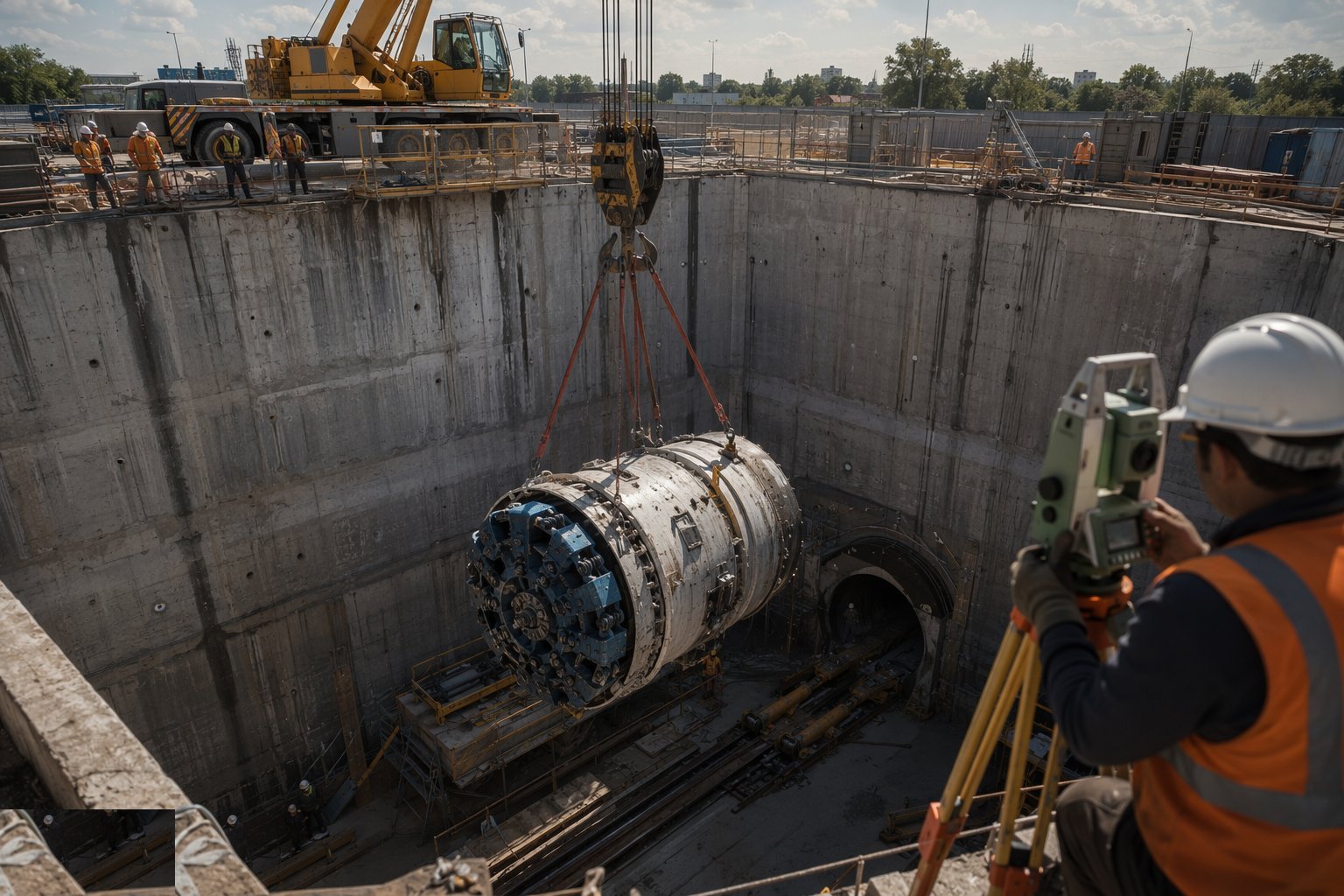
Reception is launch in reverse: the eye seal in the reception shaft, the last metres driven at reduced pressure, and the machine breaking through into the shaft on — if the guidance and the surveying did their work — the target circle. The machine is craned out, the survey closes the drive: actual line and level against design at every pipe, the as-built record the client and the adopting authority will hold you to. A drive that lands within tolerance is forgotten by breakfast; a drive that misses gets a redesign, a connecting heading, or a very long meeting.
Step 6: Grout the annulus and prove the pipe
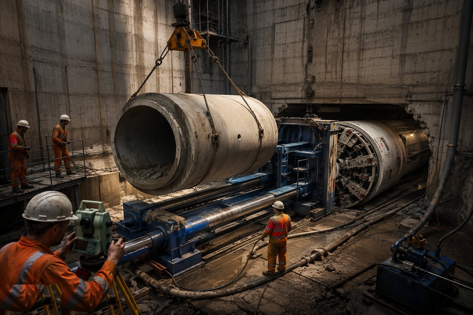
The overcut annulus around the pipe string is grouted — the lubricant displaced with a cement-bentonite grout injected through the pipe ports — locking the string into the ground and cutting off the groundwater path along the drive. Then the pipeline is proven like any other sewer: air or water test to BS EN 1610 between manholes, deflection check where the pipe is flexible, and the CCTV survey through the finished bore. Manholes are constructed in the shafts over the new pipe, channels and benching formed, and the shaft is backfilled or finished as a chamber. The drive was the drama; the testing is the evidence, and the asset is only real when the file says so.
Plant and equipment
- Microtunnel boring machines (slurry MTBM) or manned shields and roadheaders, sized to the ground and diameter
- Main jacking rig with thrust cylinders, thrust ring and guide rails; interjack stations for long drives
- Slurry pumps, separation plant and settlement tanks for slurry microtunnelling
- Shaft construction plant: piling rigs, caisson gear, cranes and grabs
- Bentonite mixing and injection plant for lubrication; grouting plant for the annulus
- Laser guidance systems — and gyro/gyroscopic systems on long or curved drives — with total station survey support
- Compressed air, dewatering or ground treatment plant where the face demands it
- Air/water test kit and CCTV crawlers for pipeline acceptance
Quality control checks
- Jacking pipes certified to the product standard with joint design approved; every pipe inspected for damage before it enters the shaft
- Thrust wall and jacking frame set-up surveyed and signed off before launch
- Jacking load and steering logs recorded per stroke and reviewed against prediction
- Drive as-built survey: line and level at every pipe against tolerance
- Annulus grouting records — volumes and pressures per pipe port
- Air or water test to BS EN 1610, deflection check where applicable, and full CCTV survey of the installed pipeline
Safety considerations
- Shaft work: deep excavation support, edge protection, ladder and rescue access, lifting over open shafts under exclusion
- Ground and groundwater at the shaft eye — uncontrolled inflow is the launch-day killer; seals, treatment and standby pumping proven first
- Confined spaces in shafts and manned bores: ventilation, gas monitoring, communications and rescue on standby
- High-pressure hydraulics and slurry systems — stored energy, burst hoses, injection injury discipline
- Heavy repetitive pipe lifts in a congested shaft — cranage, banksmen and hand injuries the daily battle
- Settlement risk to railways, highways and services above the drive — monitoring with trigger levels and a stop-work plan, not a hope
Common defects
- Steering drift beyond tolerance — a drive landing off line or off level and the manhole connections redesigned around it
- Stalled or stuck strings from lost lubrication or climbing skin friction — recovered by interjack, excavation, or not at all
- Over-excavation and surface settlement above the drive — voids grouted after the event, claims before it
- Damaged pipe joints and cracked pipes from off-axis jacking loads or pipes lowered against grit on the joint
- Shaft eye inflows at launch or reception — flooded shafts and contaminated slurry
- Ungrouted or partially grouted annulus — groundwater tracking along the drive and seepage at the manholes for years
Best suited for
- Crossings under railways, motorways, watercourses and congested service corridors
- Deep gravity sewers where open cut becomes uneconomic below five to six metres
- Urban renewals where surface disruption is politically or commercially unacceptable
- Long, level-critical gravity bores where microtunnel guidance beats open-cut accuracy
How long does Utility Tunnels & Pipe Jacking take?
Typical duration: Shafts dominate the programme — six to twelve weeks each depending on depth and ground — while the drives run at 5–15 m per shift on microtunnels and slower on manned jacking; a two-shaft 150 m drive scheme typically completes in four to eight months..