Sewer Network Construction
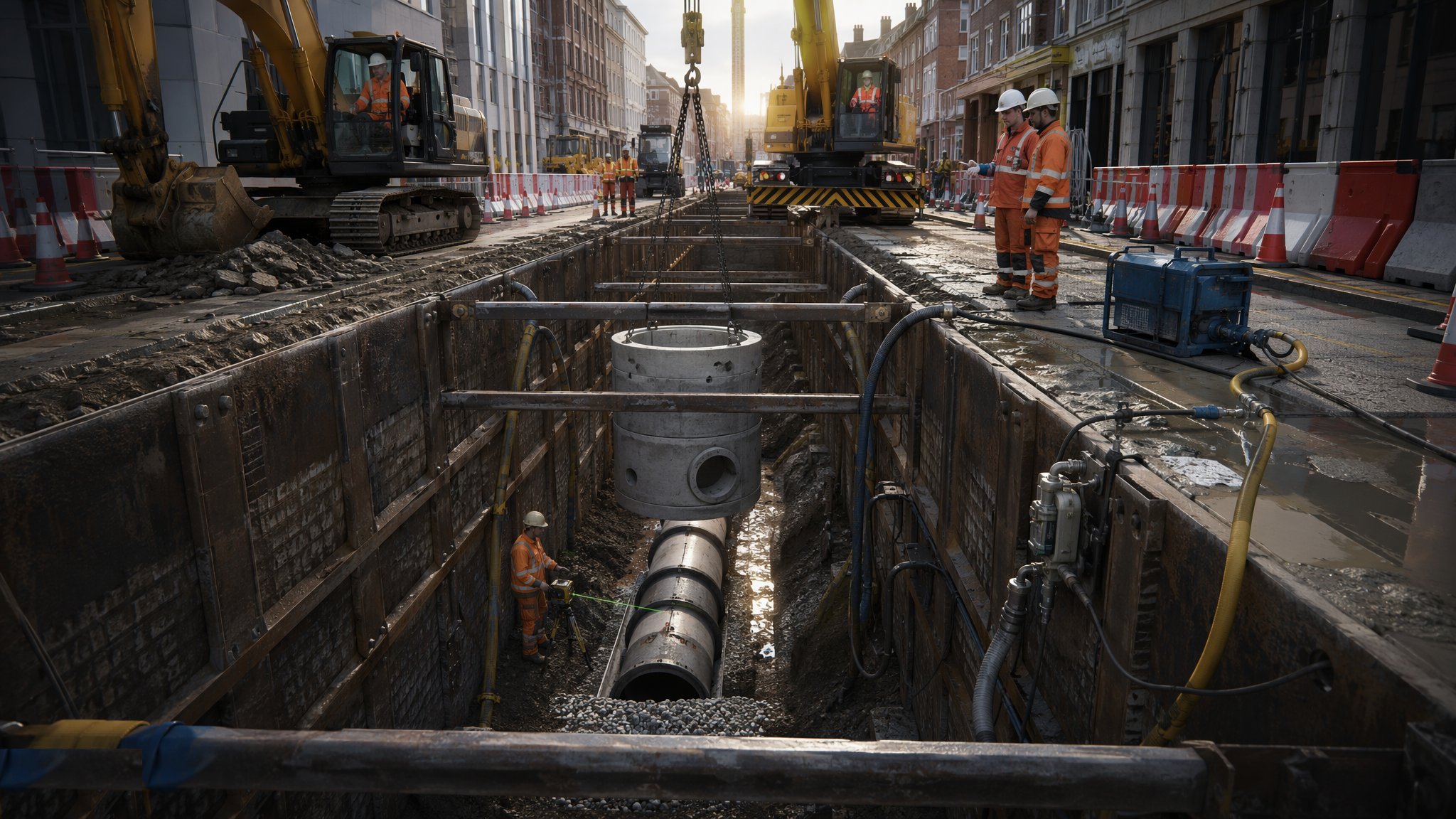
Gravity sewers laid in open cut to exact line and gradient, manholes at every change of direction, rising mains where the levels give up — tested, CCTV-surveyed and adopted before the first house connects.
Last updated 2026-07-28 by the BuildPedia Editorial Team.
What is Sewer Network Construction?
A sewer network is the least forgiving pipework on any development. Gravity does the work, so every metre of pipe is laid to a designed invert level and gradient — there is no pump downstream to rescue a backfall, and no tolerance for a pipe that ponds. UK foul and surface water sewers run from 150 mm connections up to trunk sewers of a metre or more, in vitrified clay, concrete, uPVC or GRP depending on size, ground and the adopting authority's approved list. Where the sewer will be adopted by the water company — and on most developments it will be — it is built to the adoption standards: Sewers for Adoption and its successor sewerage sector guidance in England, the Welsh equivalent, and the water company's own addenda. In the UAE the network belongs to the municipality's drainage authority — Dubai Municipality's sewerage network in Dubai, the sewerage services companies in the other emirates — and every connection and material is approved through their NOC and inspection regime.
The default construction is open cut: a trench excavated to formation, the pipe laid on a prepared bed, jointed, and backfilled in compacted layers. The bed is not an afterthought — it is a designed structural element. Bedding classes define how much of the pipe's circumference is supported: a Class B granular bed supports the lower 180 degrees with well-graded single-size aggregate; a Class S bed wraps the full surround in granular material for flexible pipes; where cover is shallow or ground is poor, the pipe may go on a Class A concrete bed or a full concrete surround. Manholes — precast concrete rings to BS EN 1917 on a cast in situ base, with benched and channelled inverts — sit at every junction, change of direction or gradient, and at prescribed maximum spacing, because every sewer must be roddable and surveyable end to end.
Where gravity runs out of fall, the network goes pumped: a rising main in welded polyethylene, pressure-rated and thrust-restrained at every bend, running from a pumping station back up to a gravity discharge point. And where the network runs deep under a live city — the big interceptor and trunk sewers — open cut gives way to deep shafts and tunnelling, and the connections to the live system are made under overpumping with the sewage still flowing past the workface. Either way, the proof of the job is the same: an air or water test to BS EN 1610 on every length, a CCTV survey coded to the Manual of Sewer Condition Classification, and an as-built invert survey that tells the adopting authority exactly what it is taking on.
When and why is Sewer Network Construction used?
Sewers go in early — they are usually the deepest services on site, and the drainage sequence on any development works uphill: deepest pipes first, shallowest last. On a new development the network is built ahead of the roads and plots it serves, because everything above it depends on the levels it fixes. The reason the standards are so rigid is adoption: the water company or municipal authority that will own and maintain the pipe for the next century inspects at hold points, witnesses the tests, and will simply refuse to adopt a sewer with a failed CCTV survey, leaving the developer maintaining private drainage forever. Gravity is always preferred over pumping because a gravity sewer costs almost nothing to run and a rising main costs energy, maintenance and a failure mode for its whole life — so the design fights for depth and gradient, and the site fights to build exactly what the design drew. Get an invert wrong by 50 mm at the downstream end of a flat gradient and you have not built a sewer; you have built a long, buried puddle.
Types of Sewer Network Construction
Open-cut gravity sewers on granular bedding
The workhorse: pipe laid on a Class B or Class S granular bed in a supported trench, jointed with push-fit ring seals, and backfilled in layers. Vitrified clay and concrete for rigidity and chemical resistance, uPVC and structured-wall plastic for the smaller diameters — all laid to laser-controlled line and level.
Concrete bed and surround construction
For shallow cover under roads, poor founding ground, or where the design needs the pipe and its bedding to act as one rigid unit: the pipe is haunched or fully wrapped in cast in situ concrete. Slower and more expensive than granular bedding, and the pipe joints need flexible treatment at the concrete joints — but nothing moves afterwards.
Rising mains
Pumped pressure pipework in PE100 polyethylene, butt-fusion or electrofusion welded into a continuous string, laid with thrust blocks or restraint at every bend and fitting, with air valves at high points and washouts at low points. Tested as pressure pipe, not gravity pipe — the hydrostatic pressure test is the pass/fail event.
Deep sewers and shaft works
Trunk and interceptor sewers too deep for open cut, built from segmental shafts with headings or by tunnelling, and connected to the live network under overpumping. A specialist game: deep excavation support, confined-space control, and flows that never stop for the programme.
Sewer Network Construction: step by step
Step 1: Clear services, set out and prove the levels
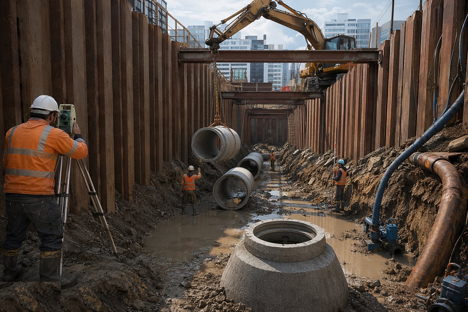
Before a bucket touches the ground, the route is scanned and trial-holed against the buried-services drawings — HSG47 practice in the UK, utility NOCs in the UAE — because a sewer trench is deep, and deep is where the 132 kV cable and the gas main live. The line is set out from survey control with the invert levels at every manhole checked against the design, and a level run closed back to datum before excavation starts. A sewer is set out by its invert, not its crown, and the traveller or laser that controls digging depth is referenced to that invert — the whole job is a levels job wearing an excavation costume.
Step 2: Excavate and support the trench
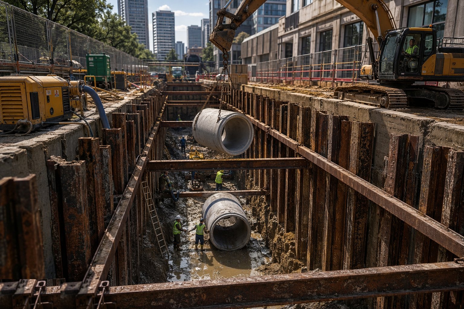
The trench is excavated to formation in the planned lengths, supported as it goes: trench boxes dragged along with the pipe in good ground, sheeted trenches or battered sides where space and soil allow. Nobody works in an unsupported trench, full stop — trench collapse kills more groundworkers than any other single cause, and a sewer trench at two to four metres deep with a man in it is exactly the profile that buries people. Groundwater is dealt with as found — sump pumping in coarse ground, wellpoints in sands — because bedding laid under water is bedding laid blind. Formation is trimmed, inspected, and any soft spots dug out and replaced before a single pipe arrives.
Step 3: Prepare the bedding
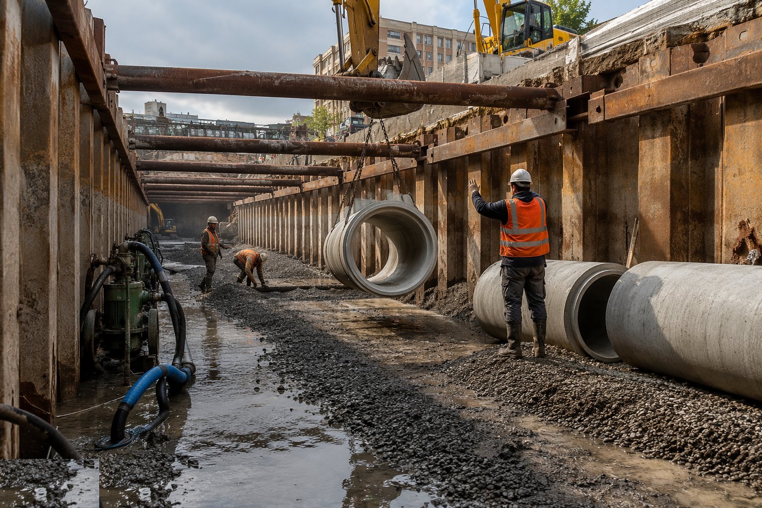
The specified bedding class is constructed to detail: graded granular material spread and compacted to the designed thickness, shaped to support the pipe barrel — not the sockets — over the full bedding angle. For Class B the bed is formed to support the lower half of the pipe with side support compacted up the haunch; for Class S the full surround goes on in layers beside and over the pipe. This is where most sewer failures are born: voids under the haunch from bedding thrown in carelessly, oversized stone against a plastic pipe, or bedding laid on a wet, pumping formation. The bed is inspected before pipes are laid on it, and the pipe layer who can see his bed can see his future.
Step 4: Lay and joint the pipes to line and level
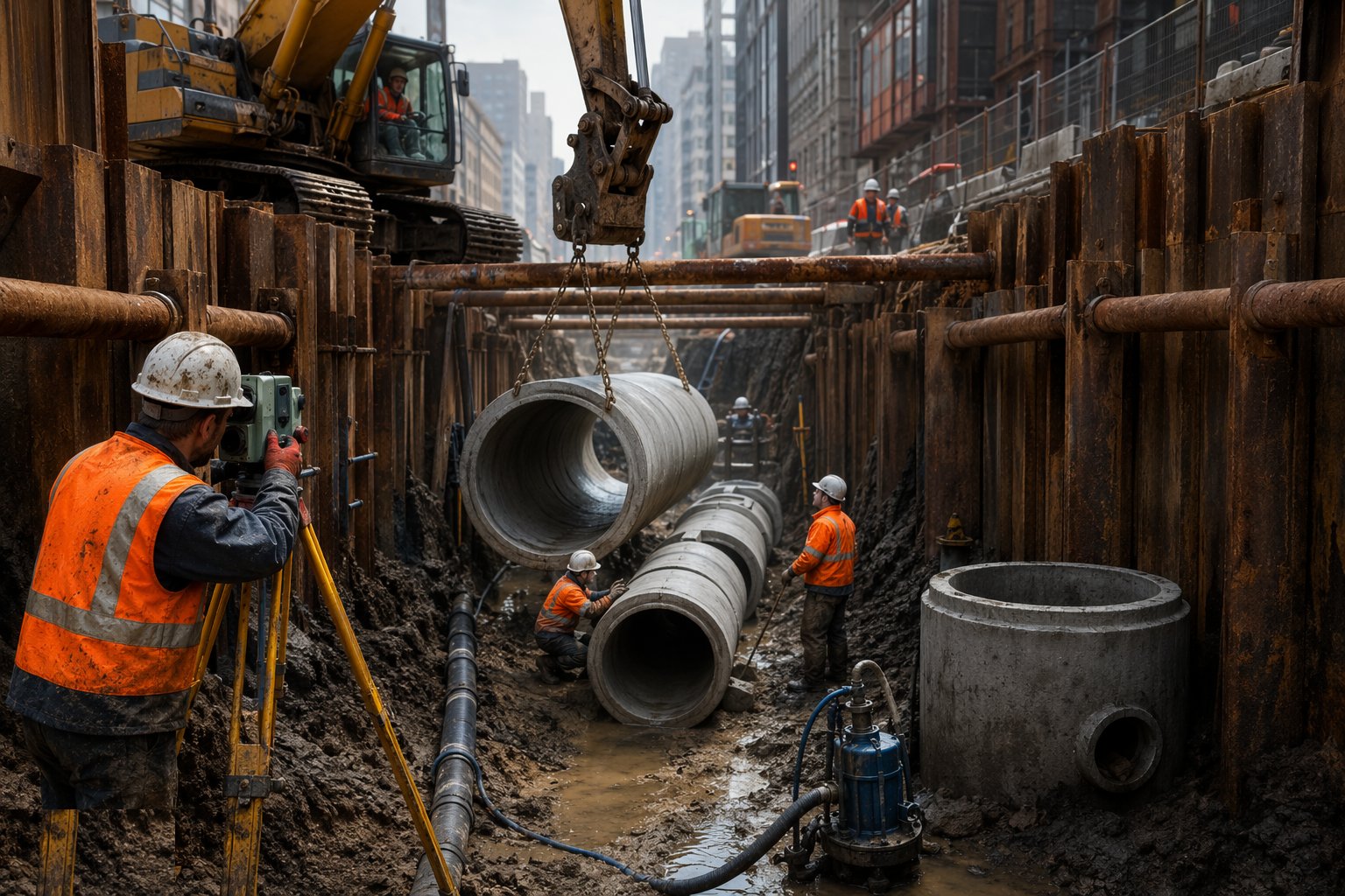
Pipes are laid uphill from the downstream manhole, socket facing upstream, each one set to line and level on a pipe laser set in the last manhole or a laser and target at the pipe. Every joint is made per the manufacturer's method — ring seals lubricated and pushed home, clay pipes jointed with their flexible couplings, concrete pipes with their specified joint — and each pipe is checked individually for line, level and joint engagement before the next goes on. Bedding side support is placed and compacted beside the laid pipe in layers as the run progresses. You do not push a pipe into line with the excavator bucket, and you do not lay on a bed you cannot see; both shortcuts come back at the CCTV survey with interest.
Step 5: Build the manholes
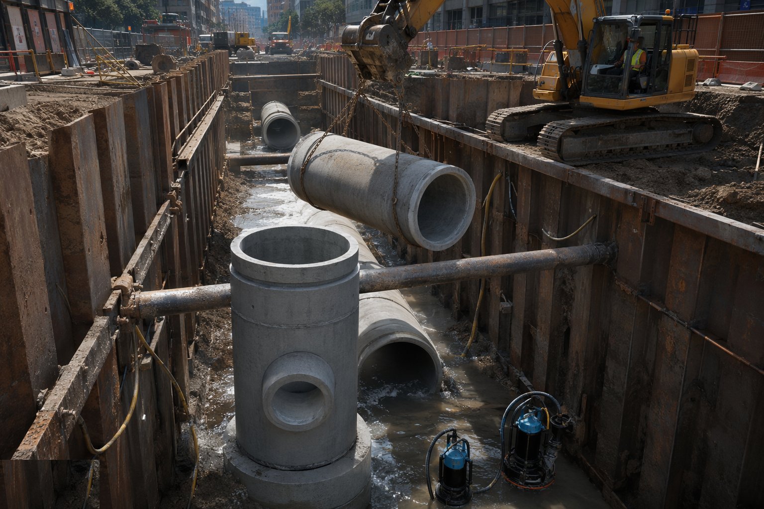
Manholes go in with the pipe, not after it. The base is cast in situ concrete or a precast base unit with the channel and benching formed to the design — channels true to the pipe inverts, benching sloped so nothing settles on it, and every branch connection channelled and benched, never left as a bare pipe stub in the wall. Precast chamber rings to BS EN 1917 are jointed and built plumb to cover level, with step irons or ladders as specified and the frame and cover set to final road or verge level at the end of the works. Benching is the fingerprint of a manhole: a water company inspector can tell the whole standard of the job from the benching in one chamber.
Step 6: Backfill and compact in layers
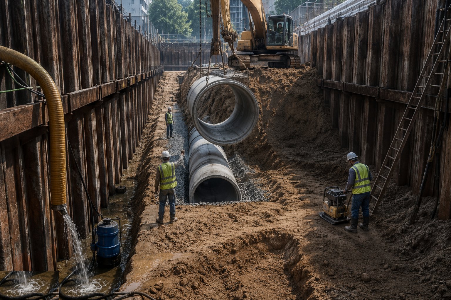
Backfill goes on in compacted layers — granular surround over the pipe to the specified cover, then selected fill or as-dug material in 150–300 mm layers compacted to specification, with mechanical compactors kept off the pipe until the cover depth allows. Under roads the backfill spec tightens to the highways standard and the reinstatement is to match. Settlement over a sewer trench is the defect that never sleeps: it shows up as a depression in the footway six months after adoption, and the cause is always the same — layers too thick, compaction too light, or wet fill dumped in a hurry at the end of a Friday.
Step 7: Test every length: air or water, then CCTV
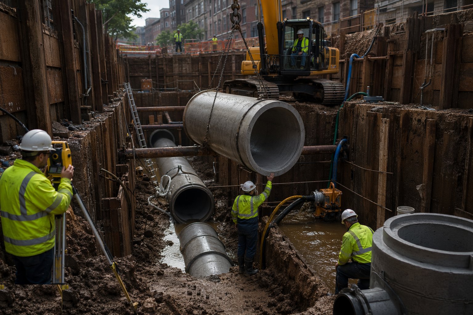
Each length between manholes is tested to BS EN 1610 — an air test on the sealed length with the pressure drop measured over the specified time, or a water test where specified — and flexible pipes are deflection-tested with a mandrel pulled through to prove the pipe has not ovaled under backfill. Then the CCTV crawler goes through every length, the survey coded to the Manual of Sewer Condition Classification, and every joint, connection and defect graded. A failed test means find it and fix it — there is no waiver route with an adopting authority, and a length that fails at the end of the job fails expensively, because by then the road is on top of it.
Step 8: Connect, commission and hand over for adoption
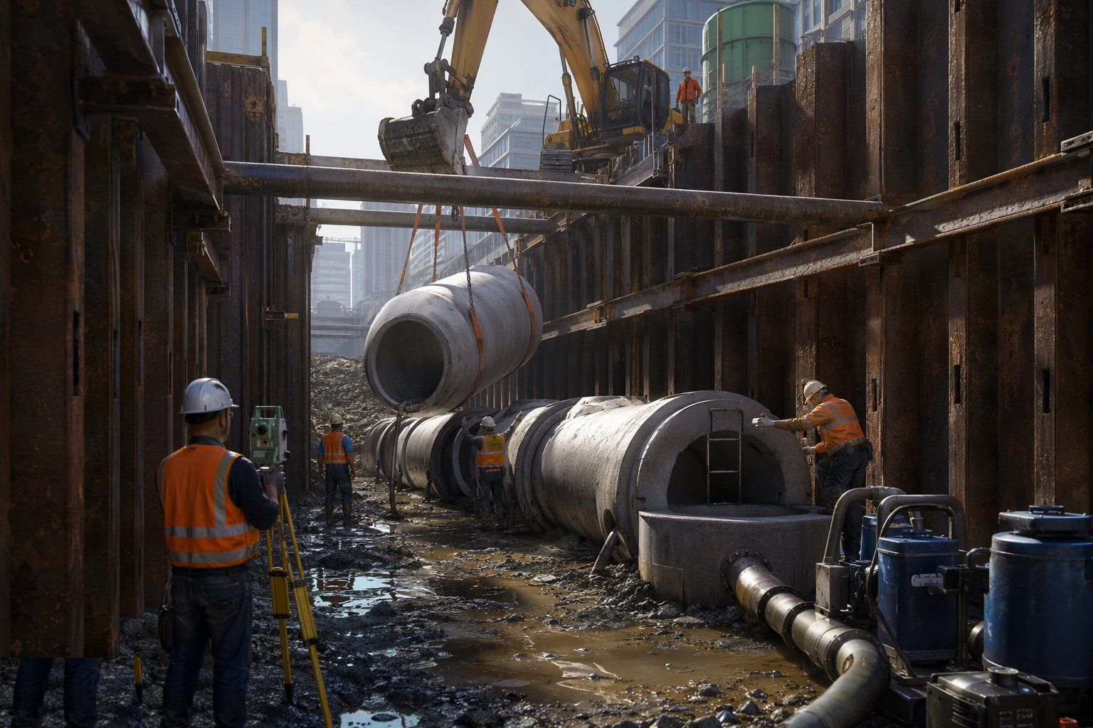
Connections to the live public sewer are made by approved methods — a junction onto an existing manhole, a new manhole over the live sewer, or a saddle connection where the authority permits — often under overpumping with the existing flow bypassed around the work. The finished network is then handed over with its file: test certificates, CCTV surveys and codings, as-built drawings with surveyed inverts, materials certificates, and the adoption inspection sign-offs. Only when the authority accepts the technical file does the sewer become theirs — and on a housing development, the adoption milestone gates the roads, the plots and the sales programme behind it.
Plant and equipment
- 360° excavators with trenching buckets, plus breakers for rock and existing manhole demolition
- Trench support: drag boxes, trench sheets with hydraulic frames, edge protection and access ladders
- Pipe lasers, laser levels and travellers for invert control
- Plate compactors, trench rammers and vibratory rollers for layered backfill
- Dewatering kit: submersible pumps, wellpoint systems and settlement tanks where groundwater runs
- Butt-fusion and electrofusion welding rigs for PE rising mains
- Air and water test kit, mandrels for deflection testing, and CCTV crawler camera systems
- Overpumping sets with duty and standby pumps for live connections
Quality control checks
- Bedding and surround materials certificated to the specified grading; pipe and joint certification checked against the adopting authority's approved list
- Line and level recorded pipe by pipe against the laser; as-laid invert survey before backfill covers the evidence
- Air or water test to BS EN 1610 on every length between manholes, witnessed at the adoption hold point
- Deflection (mandrel) test on flexible pipes after backfill
- CCTV survey of every length coded to MSCC, reviewed and accepted before adoption
- ITP hold points for bedding, pipe laying, testing and connection — no covering up without the inspection
Safety considerations
- Excavation collapse: support or batter every trench a man enters, ladder access within reach, spoil and plant back from the edge
- Buried services: scan, trial-hole and hand-dig the approaches — HSG47 in the UK, NOC service clearances in the UAE
- Sewage hazards: hydrogen sulphide and contaminated water — gas monitors, hygiene discipline, Weil's disease briefing, welfare with hot water from day one
- Confined spaces in deep manholes and shafts: entry permits, top man, rescue plan and forced ventilation
- Plant and pedestrian segregation around an open trench — the reversing excavator and the open edge are a permanent pairing to be managed
- Overpumping and live connections: flows that do not stop, flooding risk downstream, and night working under lights
Common defects
- Backfalls and ponding lengths — pipe laid off gradient, discovered at CCTV when the water stands in the invert
- Voids under the haunch from careless bedding — the pipe ovales or the barrel cracks under load
- Displaced or half-home joints — infiltration, exfiltration and a failed air test
- Manhole benching wrong or missing — debris catches, blockages start, and the inspector rejects the chamber
- Trench settlement from thick, wet, poorly compacted backfill — the depression that appears in the finished road
- Silt, offcuts and debris left in the pipe — a dirty line at CCTV and a rod-and-jet job before retest
Best suited for
- New adoptable foul and surface water networks on housing and commercial developments
- Urban sewer replacement and upsizing where open cut is available
- Gravity-first drainage design where levels allow fall to a discharge point
- Rising main links where pumping is unavoidable between gravity systems
How long does Sewer Network Construction take?
Typical duration: A two-excavator crew lays 150–300 mm sewer at roughly 20–40 m per day including bedding and backfill, plus about a day per manhole — a 500 m estate network with ten manholes typically takes six to ten weeks, with testing and CCTV adding two to three more..