Airfield Ground Lighting & Navigational Aids
The airfield's nervous system — series circuits at constant current, inset and elevated lights, transformer pits and ducted cable, the control system in the tower, and the ILS and PAPI that only count once a calibration aircraft has flown them.
Last updated 2026-07-28 by the BuildPedia Editorial Team.
What is Airfield Ground Lighting & Navigational Aids?
Airfield ground lighting — AGL — is a specialist electrical discipline most electricians never meet. Runway and taxiway lights do not run on mains voltage in parallel like street lighting; they run on series circuits fed by constant current regulators that hold the loop at a fixed current — classically 6.6 amps, with modern systems stepping down through selectable levels for brilliancy control. Every light sits on its own isolating transformer in a pit or base, tapped into the series loop by separable primary and secondary connectors, so one failed lamp does not darken the rest, and one excavator's near-miss does not take the runway dark — it trips the regulator's earth fault protection instead, which is exactly what that protection is for.
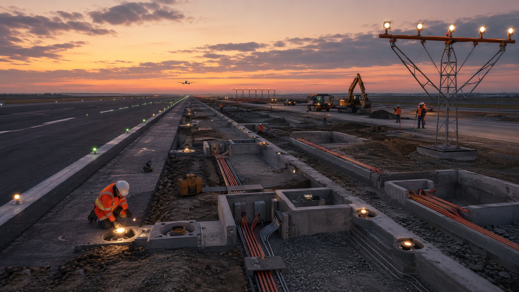
The hardware splits into two families. Elevated lights — runway edge, approach masts, taxiway edge — stand on frangible mountings beside the pavement, frangible so an aircraft that meets one breaks it away without losing a wing. Inset lights — runway centreline, touchdown zone, stop bars, taxiway centrelines — sit flush in the pavement, cored and set into the slab or asphalt, built to be run over by main landing gear at full weight. Around them runs the civils infrastructure: primary cable laid in ducts with draw pits at intervals, transformer pits, saw-cuts across pavements for secondary connections, and the earthing and equipotential bonding that ties the system together. Installation is half electrical, half civil — and, on a live airfield, almost entirely at night.
Above the lights sit the navigational aids the pilots actually fly: the instrument landing system with its localiser and glide path arrays, distance measuring equipment, and the visual approach slope indicators — PAPIs — set at precise angles beside the runway. These are systems with critical and sensitive areas around them where construction, parked cranes, even accumulated spoil can distort the signal in space, so their installation, and any work near them, is coordinated to the metre. And the final arbiter of all of it is not a meter but an aircraft: flight inspection and calibration, by a specialist aircraft flying the approaches and measuring the signals and light angles in the air, is what turns an installation into an operational aid. Ground test everything, then fly it — because the pilot's instrument does not read your test certificates.
When and why is Airfield Ground Lighting & Navigational Aids used?
AGL and nav aid work happens at new-build airfields as part of the runway package, but the bread and butter is renewal on live airports: cables age in wet ducts, inset fittings wear under tyres, LED conversions sweep the industry, and every pavement reconstruction drags the lighting with it. The work matters disproportionately to its cost because the lights are the airport's all-weather licence: lose runway lighting capability in fog and the airport drops to restricted operations or closes, with the diversions and the headlines to match. It is also unforgiving work to fake: series-circuit faults are subtle, water in a pit is a time bomb, and a PAPI set a fraction off its angle is a hazard promulgated as an aid — which is why the regime ends with witnessed ground tests and a calibration aircraft, and why the people who do it well are a small, specialist, much-prized trade.
Types of Airfield Ground Lighting & Navigational Aids
Series-circuit AGL with constant current regulators
Constant current series loops feeding lights through individual isolating transformers, with selectable brilliancy steps from the tower. The universal architecture: robust against single failures, straightforward to fault-find with the right training, and the standard the world's runways run on.
Inset pavement luminaires
Centreline, touchdown zone and stop bar lights set flush into concrete or asphalt, with shallow or deep bases and prism or LED optics. The fittings that take the tyres: installation tolerance in millimetres, and a coring and setting operation that lives inside night possessions.
Elevated and approach lighting
Edge lights, approach centreline and crossbar arrays, threshold and end lights on frangible poles, sequenced flashers on the big approach systems. The visual ramp the pilot flies down: tall, frangible, surveyed, and unforgiving of a misplaced mast.
Instrument landing systems
Localiser and glide path antenna arrays with their shelters, monitors and critical/sensitive areas, plus DME and marker beacons where fitted. Radio navigation engineering on a construction site: the arrays are aligned to fine angular tolerances and the ground they sit on is part of the antenna.
Visual approach slope indicators
PAPI and APAPI units set at calibrated angles beside the runway, with obstacle clearance geometry behind every setting. Four boxes and a light path measured in fractions of a degree — checked on the ground, proven from the air.
Airfield Ground Lighting & Navigational Aids: step by step
Step 1: Install the ducts, pits and civils
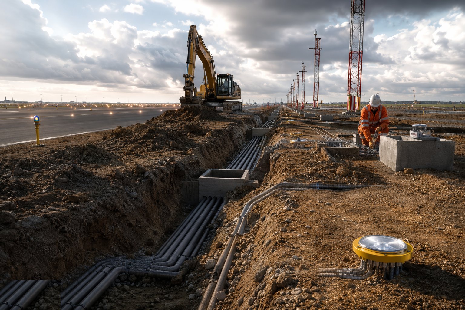
Primary cable ducts and draw pits go in with the pavement works or ahead of the electrical team: routes surveyed on the aerodrome grid, pits levelled to pavement falls, spare ducts roped and capped, and every crossing of a live or future pavement sleeved. The civils are the system's working life — a crushed duct or a pit that ponds is a fault schedule for the next twenty years — so falls, bedding and sealing are inspected as carefully as the cable that follows.
Step 2: Pull, joint and test the primary cable
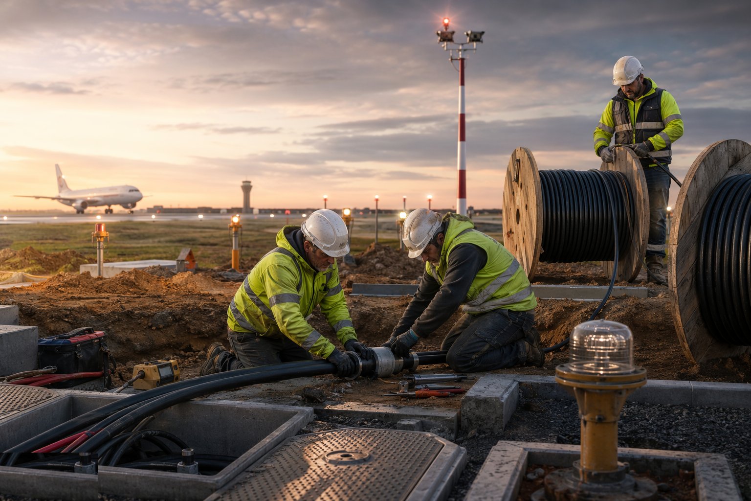
Series-loop primary cable is pulled through the ducts, jointed with the specified kits at pits, and tested section by section: insulation resistance, continuity and earth fault levels recorded against the regulator's protection settings. Joints are made dry, clean and by the book — a series circuit at kilovolts between joints forgives nothing — and every pit is labelled and logged on the circuit record before backfill.
Step 3: Set transformer pits and mount the fittings
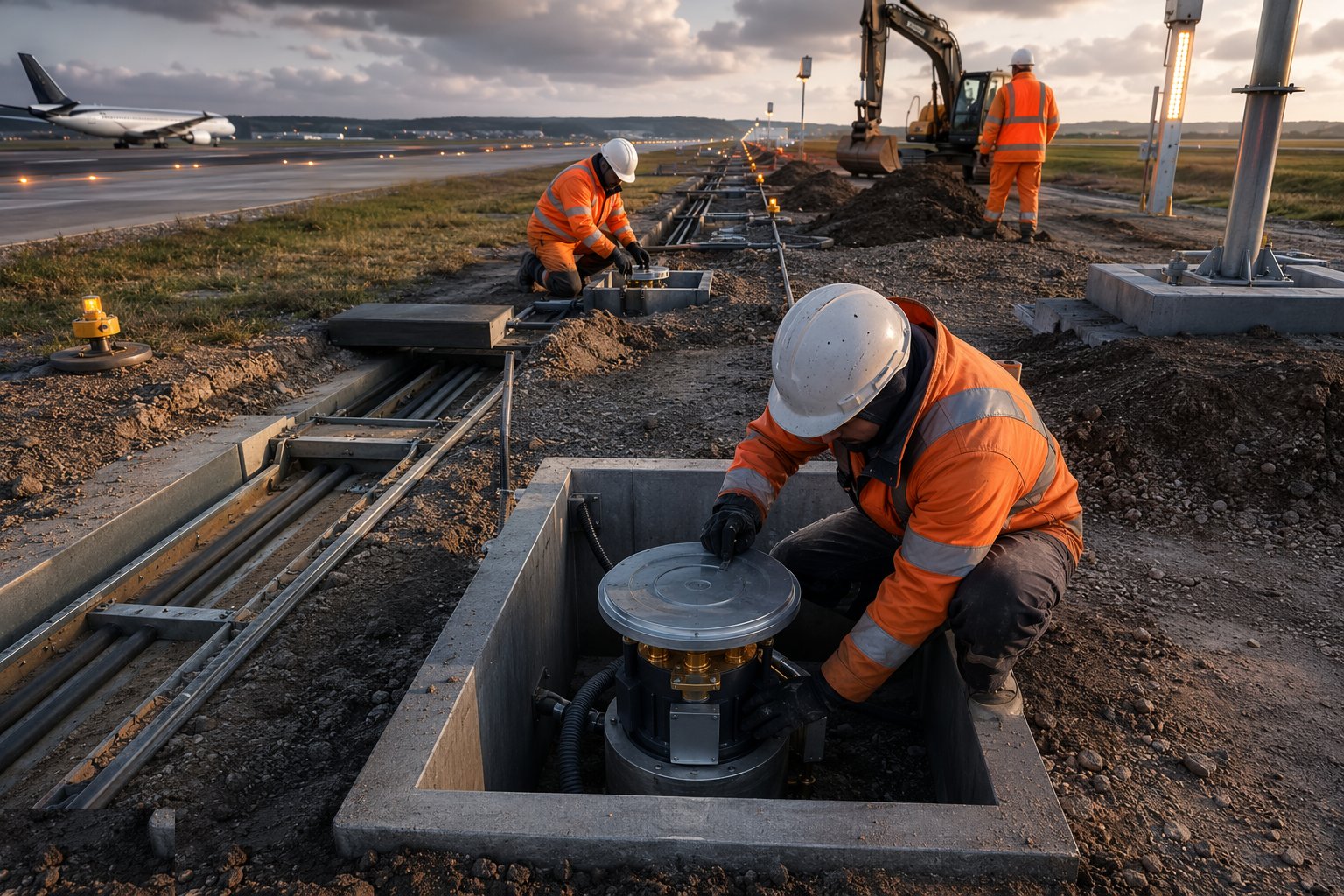
Each light position gets its base or pit set to line and level: elevated fittings on frangible couplings at the surveyed offsets, inset fittings cored into the pavement and bedded flush with the surface. Isolating transformers and connectors are installed to the manufacturer's torque and sealing requirements — the connector is the classic failure point, and the classic failure starts with water past a badly made seal. Inset work on live pavements runs in possessions, with the coring, setting and curing timed to the handback.
Step 4: Commission the regulators and the control system
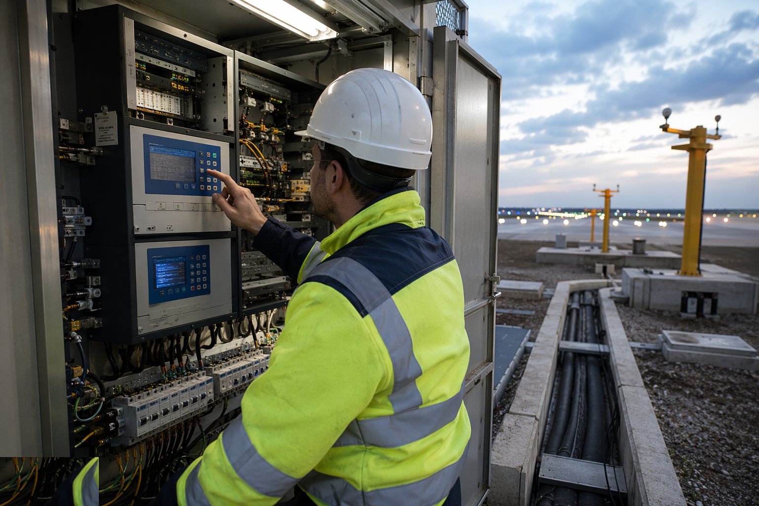
The constant current regulators are set up for their circuits — output steps matched to the brilliancy requirements, protection settings proven — and the AGL control and monitoring system is integrated with the tower: every circuit selectable, every failure annunciated, stop bars and guard lights interlocked with the tower's control logic. Cause and effect is tested from the tower desk, not assumed from the schematic: select, confirm, fail, annunciate, restore.
Step 5: Install and align the nav aids
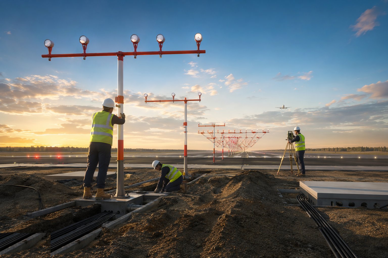
Localiser and glide path arrays are erected on their surveyed foundations and aligned to the manufacturer's procedures — antenna positions, monitor references and shelter equipment installed, with the critical and sensitive areas marked and protected from the day the array stands. PAPI units are set on their platforms and angled by ground calibration to the design eye height and glide slope, their obstacle clearance surveyed. Around every nav aid the construction discipline holds: no plant, spoil or structure in the protected areas without the authority's say-so.
Step 6: Ground test the whole system
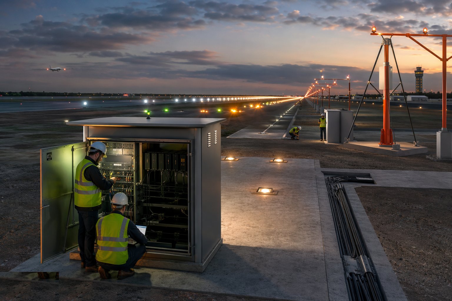
Before flight inspection, everything is proven on the ground: circuit insulation and load tests, brilliancy and photometric checks on sample fittings, inset fitting torque and projection heights, stop bar interlocks, nav aid ground checks with portable test equipment, and the maintenance regime established with spares on the shelf. The ground test file is the evidence the system is ready to be flown — and the baseline every future fault is measured against.
Step 7: Flight check and hand over to operations
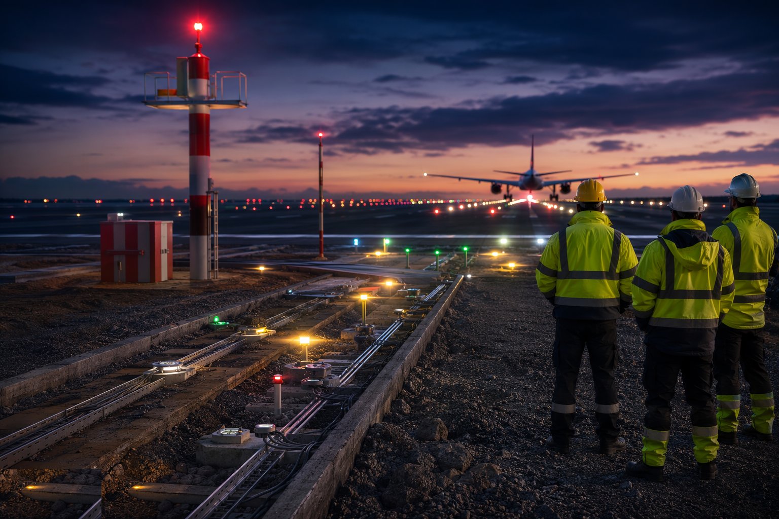
The calibration aircraft flies the procedures: ILS signals measured in space and adjusted to tolerance, PAPI angles verified from the air, approach and runway lighting photographed and assessed on final approach. Only after flight inspection passes does the aid enter service — the NOTAM declares it, the tower takes control and the maintenance handover begins. The last signature on an AGL job belongs to a pilot, and everyone on the site knows it.
Plant and equipment
- Cable pulling and jointing kit for series primary circuits; insulation and earth-fault testers
- Coring rigs and setting templates for inset luminaires in live pavement
- Torque and sealing tooling for isolating transformer connectors
- Photometric and brilliancy test equipment; portable ILS/PAPI ground test sets
- Survey instruments for mast alignment, offsets and PAPI angle setting
- Frangible masts, pits and bases; LED and tungsten fitting stocks and spares
Quality control checks
- Insulation resistance and continuity records per circuit section against regulator protection settings
- Joint and connector records: location, kit, maker and test result per pit
- Inset fitting installation records: core, bedding, flushness and torque verified per position
- Circuit selectivity and stop-bar interlocks cause-and-effect tested from the tower and witnessed
- Nav aid alignment records and critical/sensitive area protection logs
- Flight inspection reports filed as the acceptance evidence — ground tests alone do not commission an aid
Safety considerations
- Series circuits at lethal voltages: dead working, proven isolation and earthing before a joint is touched
- Airside night working: possessions, FOD discipline and the handback deadline, as for all airfield works
- Coring and saw-cutting in pavement: dust, slurry and silica controls, with captured arisings kept off the strip
- Work beside nav aid critical areas: no unauthorised plant or material within the protected zones
- Excavations and open pits on the airfield: barriered, lit, and closed or plated before every handback
- Radio-frequency awareness around live nav aid antennas — controlled access and lockout where required
Common defects
- Water in pits and connectors — the intermittent earth fault that appears with the rain and vanishes with the sun
- Joints made damp or dirty — series-circuit failures months later, one dark centreline at a time
- Inset fittings set proud or low — tyre strikes, snowplough strikes and a maintenance blame game
- Ducts crushed or unsealed at pavement crossings — the cable pull that should have been possible and is not
- Construction in the ILS critical area bending the course — found expensively by the calibration aircraft
- PAPI angles set on paper, not surveyed — flight check failures and a re-mobilisation to move four boxes
Best suited for
- New runway and taxiway lighting on greenfield airfields
- AGL renewal and LED conversion on live airports
- ILS, DME and PAPI installation and relocation works
- Stop bar, guard light and tower control system upgrades
How long does Airfield Ground Lighting & Navigational Aids take?
Typical duration: A full runway AGL installation runs 6–12 months within the pavement programme; night-possession renewal of a runway's centreline and edge lighting typically spans one full closure season, with flight inspection and entry into service adding weeks at the end..