Bridge Foundations & Substructure
Piled foundations, pile caps, abutments and piers — everything between the ground and the bearings.
Last updated 2026-07-28 by the BuildPedia Editorial Team.
What is Bridge Foundations & Substructure?
The substructure is everything from founding level up to the underside of the bearings: the piles or spread foundations, the pile caps, the abutments with their wing walls, and the piers and crossheads that the deck will eventually sit on. Unlike a building foundation, a bridge substructure is sized for aggressive horizontal actions as well as vertical load — braking and traction from the deck, thermal movement dragged through the bearings, and the full weight of retained earth pushing on the back of every abutment. Where the crossing is a watercourse, add scour: foundations are founded below the design scour depth, because a river that shifts its bed can expose a shallow foundation in a single flood season.
In the UK, bridge foundations are designed to Eurocode 7 (BS EN 1997) from the ground investigation, with piling executed to BS EN 1536 and specified to Series 1600 of the Specification for Highway Works. Piles are proved before they are trusted: integrity testing on every shaft as a minimum, with static or dynamic load tests on working or preliminary test piles. Structural concrete is to BS 8500 / BS EN 206 with durability classes matched to the exposure, and the design working life intent for highway structures is 100 to 120 years depending on the overseeing organisation — which is why cover, crack control and concrete quality here are not negotiable.
In the UAE the ground writes its own specification. Coastal zones mean sabkha, loose dune sands and saline groundwater often within a couple of metres of the surface, so bored cast in situ piles under support fluid are the default, and the concrete is engineered for chloride and sulphate attack — low water-cement ratios, GGBS or microsilica blends, and exposure classes in the XS/XA range of BS EN 206. RTA bridge practice in Dubai and the equivalent authority standards in Abu Dhabi both lean heavily on marine-grade durability detailing, because chloride-induced reinforcement corrosion is the single biggest killer of Gulf structures.
When and why is Bridge Foundations & Substructure used?
The substructure is built immediately after the structure site is accessed and the ground investigation interpreted, because every superstructure operation — beam delivery, deck casting, bearing installation — stands on it, and because buried work is the least forgiving: once the pile cap is backfilled, the piles can never be inspected again. Every stage is therefore a hold point with signed-off records, and a delay here is a delay to the entire structure, not just one workfront. There is no domestic version of a bridge substructure — the closest a small site comes is a pad footing for a garden bridge or a private culvert headwall, where the formation is still inspected against the ground information before concrete, because water and retained earth load a small wall by the same rules as a motorway abutment.
Types of Bridge Foundations & Substructure
Driven piles
Precast reinforced concrete, steel tube or H-section piles hammered or vibrated to a set. Fast and self-proving — every blow is a load test of sorts — and ideal where a dense stratum or rockhead is the target. Noise, vibration and headroom limit them near live infrastructure and sensitive neighbours, and obstructions can refuse a pile mid-drive.
Bored cast in situ piles
Large-diameter rotary bored or CFA piles, drilled to depth and concreted in place — by tremie under support fluid (bentonite or polymer) where the bore is unstable or below water, which in Gulf ground is most of the time. Quiet and capable of very high loads and great depths, but the concrete goes in blind, so integrity testing and strict control of the bore, the cage and the pour are everything.
Spread foundations
Pads or strip footings founded directly on rock or competent ground — the simple option where the ground allows it, common for small overbridges and where rockhead is high. Cheap and quick, but totally dependent on the founding stratum being what the GI said it was: the formation is inspected and approved by the geotechnical engineer before blinding goes down.
Caissons and deep foundations
For major crossings — wide rivers, deep water, very heavy spans — sunk caissons or large-diameter deep shafts take the loads to depth. Specialist work with compressed-air or slurry techniques, sinking controls and tremie seals, planned and monitored as a project within the project.
Bridge Foundations & Substructure: step by step
Step 1: Establish the structure site
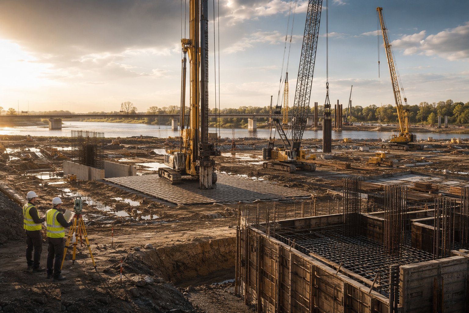
Set out the foundation positions from corridor control and establish the working platform: a designed, inspected piling mat for the rigs (the FPS Working Platform Certificate is signed over to the piling contractor in the UK), hard standing for cranes and concrete deliveries, and drainage that keeps the platform dry. Where the foundations sit in or beside a watercourse, install the cofferdam, flume or temporary diversion first, under its own environmental consents — working in water is a different job entirely.
Step 2: Install the piles
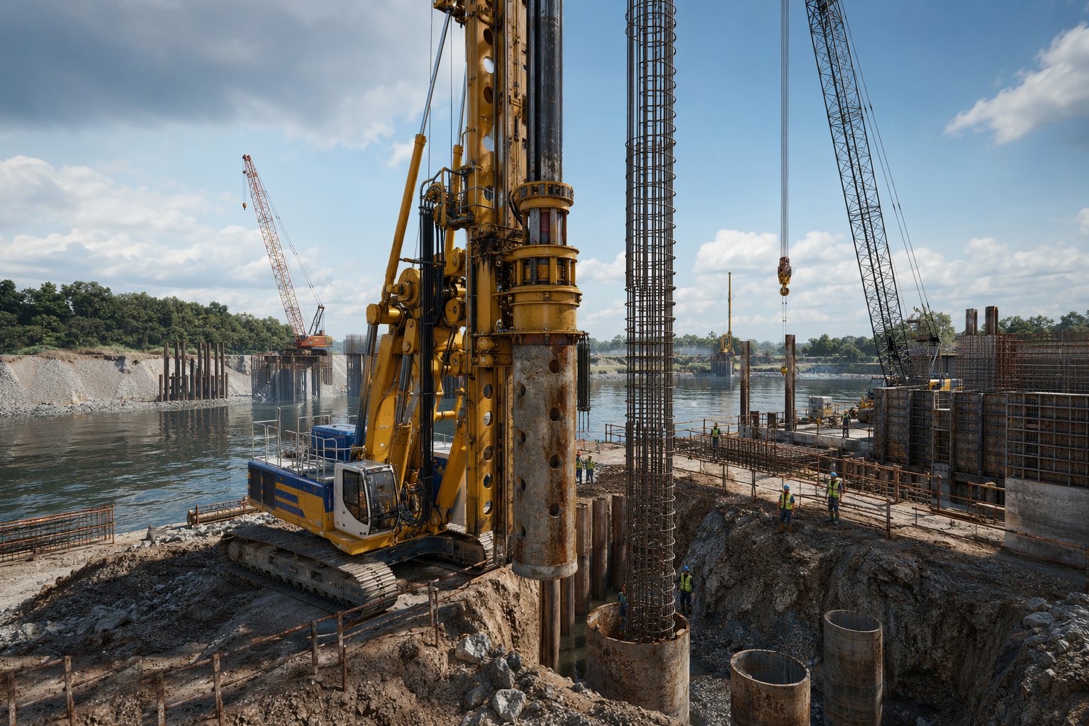
Drive or bore each pile to the specified depth or set, logging every one: penetration records and final set for driven piles, bore logs, support fluid properties and tremie volumes for bored piles. Positional and verticality tolerances are tight — piles out of position force redesign of the cap. In saline Gulf ground, cages are detailed for the durability class and concrete is placed promptly after boring; an open bore left overnight in running sand is a lost pile.
Step 3: Test and accept the piles
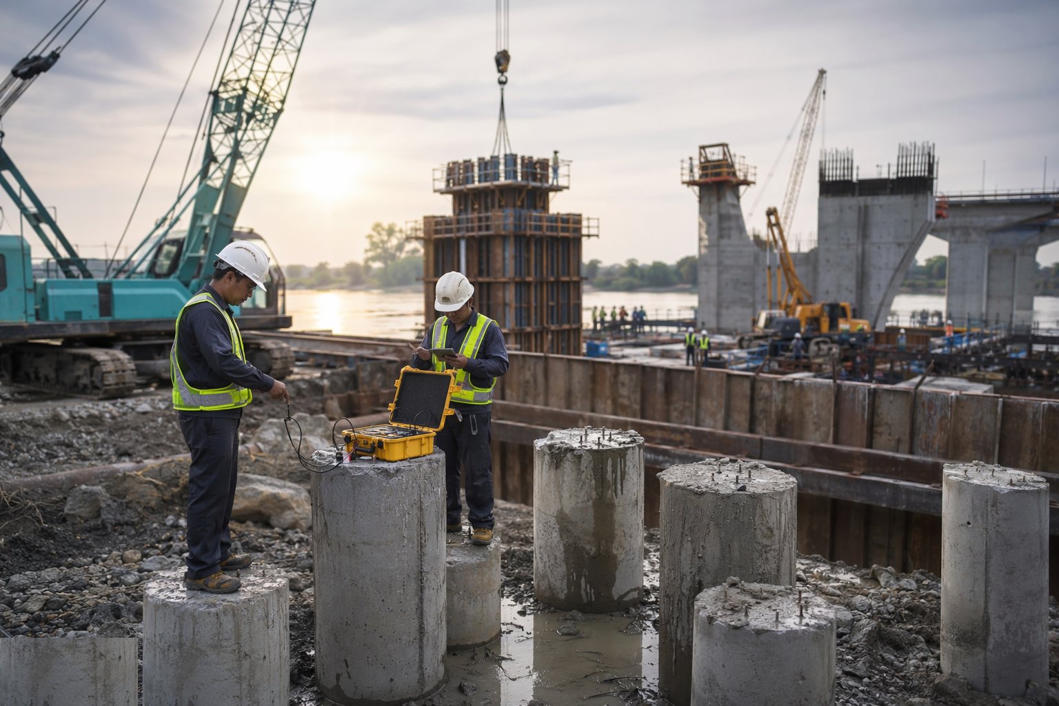
Integrity-test every pile (low-strain sonic echo as routine, crosshole sonic logging on critical large-diameter shafts) and load-test per the specification — static maintained-load tests on preliminary or selected working piles, dynamic testing as a production check. No cap is constructed over an unaccepted pile. Failures trigger an investigation: extra coring, replacement piles, or a redesigned cap, all agreed with the designer before proceeding.
Step 4: Break down pile heads and construct the pile caps
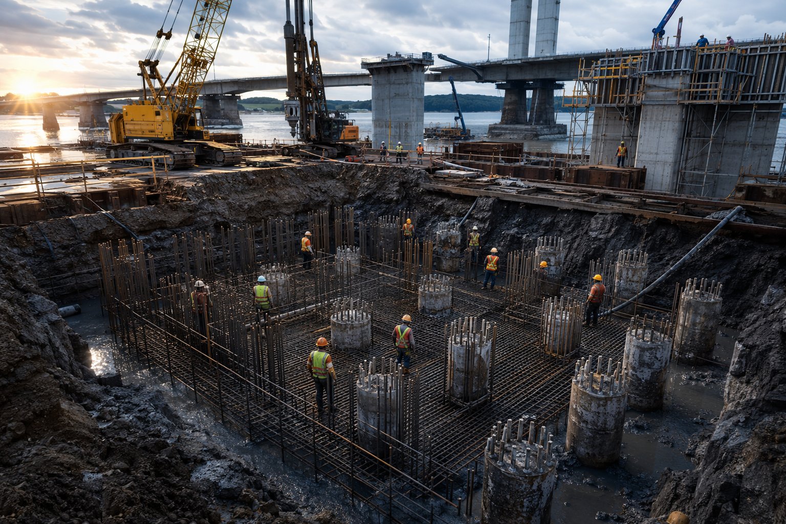
Crop the piles to cut-off level, exposing sound concrete and the projecting bars, and check the exposed head against the test records. Fix the pile cap reinforcement — these are heavily congested cages with starter bars for the columns or walls above — and cast on blinding, with the formation approved first. Keep the pour continuous, cure it properly, and strike the sides only when the concrete has the strength to carry itself and the next operation.
Step 5: Cast the abutments, wing walls and piers
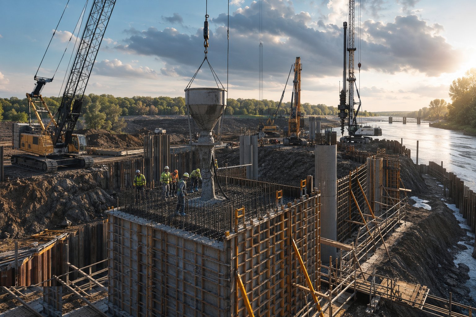
Erect the formwork — substantial panels on strongbacks, tied and braced, with a temporary works design and check under BS 5975 for anything of consequence — and fix the reinforcement with the specified cover on all faces. Cast in planned lifts with properly prepared construction joints, vibrate thoroughly, and cure: in a UK winter that means insulation; in a Gulf summer it means shading, cool concrete, and wet curing from the moment the surface can take it. Pier columns are checked for line and plumb before the formwork is released.
Step 6: Construct the crossheads and bearing plinths
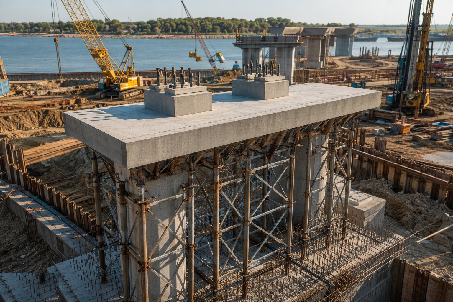
Crossheads (piers caps) sit at the top of the piers and take the bearing line — heavily reinforced, often prestressed, and cast on falsework designed to BS 5975 with the Temporary Works Coordinator controlling the pour and the strike. On top of every crosshead and abutment, cast the bearing plinths (plinth stones) to tight level tolerances with their holding-down bolts or dowels accurately set: the bearings to come can only be as good as the surface they land on.
Step 7: Backfill, drain and waterproof behind the abutments
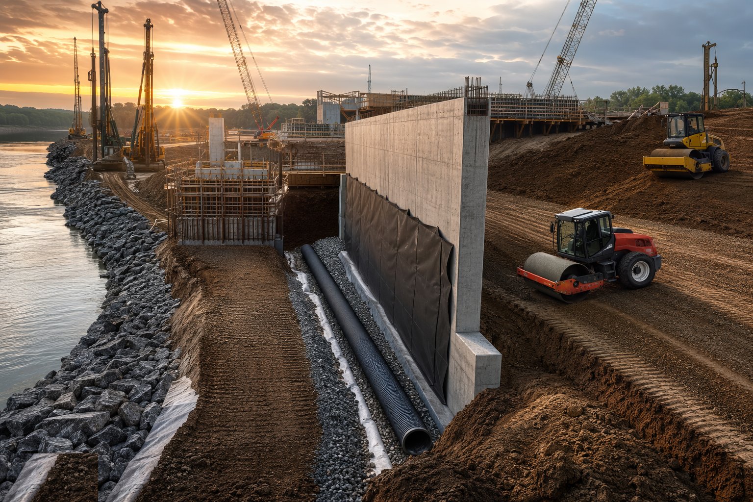
Apply the specified protective coating or waterproofing to the buried faces, install the drainage layer and weep holes or drainage pipe behind the abutment — trapped water behind a wall doubles the pressure on it — and backfill in thin compacted layers with the specified material, compacted evenly on both sides where the detail demands it. Heavy compaction plant is kept off the wall face; hand-held compactors work the last metre. Settlement of the approach fill here is what causes the notorious bump at the end of the bridge.
Plant and equipment
- Piling rigs: rotary bored, CFA, or driven rigs with hammers/vibrators
- Support fluid plant: bentonite/polymer mixing, tanks and desanding units
- Cranes for cages, formwork and concrete skips
- Pile cropping and breaking equipment; hydraulic breakers
- Formwork panels, strongbacks, soldiers and falsework for crossheads
- Concrete pumps and tremie pipes; poker vibrators
- Integrity testing (PIT) and crosshole sonic logging equipment
- Survey instruments: total stations and precise levels
Quality control checks
- Pile installation records per pile: depth, set or bore log, fluid properties, concrete volumes
- Integrity tests on all piles; load tests per specification, accepted before caps proceed
- Founding formation inspected and approved by the geotechnical engineer before blinding
- Concrete to BS 8500 durability class: cube/cylinder results, cover meter surveys, crack inspections
- Bearing plinth levels and holding-down positions surveyed against tolerance before sign-off
- Backfill behind abutments: material compliance and density tests per layer
- Sulphate and chloride exposure class verified for all buried concrete in saline ground
Safety considerations
- Piling rig stability on a designed and maintained platform — rig overturn is the killer risk
- Fall protection at excavation edges and open bores; covers or barriers on every bore
- Deep excavations for caps: battered, benched or supported, with ladder access
- Concrete operations: burns from cement, pump line blow-outs, vibrating poker injuries
- Working over or beside water: life jackets, rescue plan and edge protection
- Lifting operations for cages and formwork under planned, supervised lifts
- Heat stress management and midday-break compliance for Gulf summer pours
Common defects
- Soft toe or necking in bored piles from poor bore control — found by CSL after the cap is designed
- Piles outside positional tolerance forcing a redesigned, heavier pile cap
- Insufficient cover on buried faces — the corrosion clock starts ticking at year one
- Honeycombed construction joints in abutment walls leaking groundwater
- Bearing plinths cast out of level — bearings shimmed and packed as a permanent bodge
- Poorly compacted abutment backfill: the approach slab dips and the bump at the bridge end appears
- Support fluid contaminated or under-specified, collapsing bores in running sand
Best suited for
- Piled foundations carrying concentrated span loads
- Abutments and piers beside rivers, railways and live corridors
- Works over or in water with cofferdams and temporary access
- Substructures where settlement tolerance is measured in millimetres
How long does Bridge Foundations & Substructure take?
Typical duration: 3–6 months for a typical two-abutment overbridge with piled foundations; 12 months and more for multi-pier viaducts or crossings in water with cofferdams..