Bridge Deck Construction
Forming the span itself — in-situ decks on falsework, precast beams with an in-situ slab, and post-tensioned construction.
Last updated 2026-07-28 by the BuildPedia Editorial Team.
What is Bridge Deck Construction?
The deck is the part everyone thinks of as the bridge: the structure that spans the gap and carries the load. How it is built is decided by span, clearance, what is underneath, and programme. Short to medium spans over ground you can stand on favour an in-situ reinforced concrete deck cast on falsework. Where there are many repeats, precast prestressed beams placed by crane and stitched together with an in-situ slab win on speed and factory quality. Longer spans, or anything that must stay slim and continuous, go post-tensioned — in-situ box girders with tendons threaded through ducts and stressed after the concrete hardens.
In the UK, anything that temporarily holds up fresh concrete is temporary works and falls under BS 5975: a Temporary Works Coordinator controls it, the falsework is designed and independently checked, and nothing is loaded until the check certificate exists. Deck concrete is specified to BS 8500 / BS EN 206 and Series 1700 of the Specification for Highway Works, executed to BS EN 13670. Post-tensioning is specialist work done by certified operatives — CARES-certified post-tensioning companies are the norm — with every stressing operation recorded: force, elongation, and the jack calibration behind them.
In the UAE the same methods apply, filtered through heat and chloride. Deck pours are planned for the cool hours, concrete arrives chilled or with ice in the mix water, and curing starts the moment the surface allows because plastic shrinkage cracking in hot, dry wind is measured in minutes, not hours. Precast segmental and beam construction dominates long viaducts — the elevated sections of the Dubai Metro were built largely with precast segmental spans — and the concrete everywhere is blended for chloride resistance.
When and why is Bridge Deck Construction used?
Deck construction follows the substructure because the deck stands on it — but it often runs just behind, pier by pier, so the erection sequence is planned as one continuous operation. It is the most visible and most unforgiving part of the structure: a deck cast with the wrong camber, or stressed with a tendon short of load, cannot be quietly fixed later. Every dimension, pour and stressing record feeds directly into the durability and the eventual ride quality of the road or track on top. The house-scale descendant of the precast beam deck is the beam-and-block ground floor: factory beams lifted or barrowed in, blocks infilled, everything stitched by a topping — factory quality, fast erection and no falsework, for the same reasons.
Types of Bridge Deck Construction
In-situ deck on falsework
Reinforced concrete slab or box cast in place on falsework supported from the ground. Total freedom of geometry — curves, tapers, varying depth — but the falsework needs firm ground and clear access underneath, and the deck is out of action to everything else until it is struck. The traditional method for overbridges and odd shapes.
Precast beam deck with in-situ slab
Factory-made prestressed beams — T-beams, U-beams, box beams — lifted onto the bearings by crane, then stitched: deck slab cast across them on permanent formwork, diaphragms at the ends, continuity over the piers where the design is integral. Factory quality, fast erection, and minimal work over live traffic or water; the beams arrive when the programme says, not when the weather allows.
Post-tensioned in-situ construction
Continuous box girders and deep decks with high-strength tendons in ducts, stressed from jacks after the concrete reaches transfer strength. Prestress keeps the concrete in compression, so spans go further with less depth and fewer cracks. Grouting the ducts after stressing is what protects the steel — a badly grouted duct is a corrosion time bomb, which is why grouting is a witnessed, recorded operation.
Steel–concrete composite decks
Steel plate or box girders erected first, with a reinforced concrete slab cast on top, connected by shear studs so steel and concrete act as one. The steelwork arrives fabricated and protected, erection is fast, and the concrete deck pour is smaller and simpler than a full in-situ deck. Common for railway and longer highway spans.
Bridge Deck Construction: step by step
Step 1: Confirm the substructure is ready
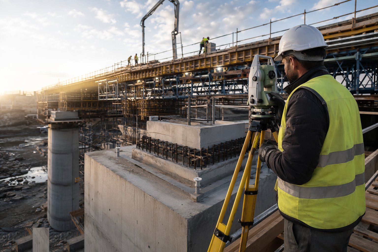
Before any deck work, verify the interface: bearing plinth levels surveyed and accepted, bearings installed or ready per the erection sequence, dowels and continuity reinforcement projecting as detailed, and the substructure concrete at required strength. Set the deck datum and camber targets from survey control — the finished profile of the road or track is already locked in here, because the deck soffit plus camber determines everything above.
Step 2: Design, erect and check the falsework and formwork
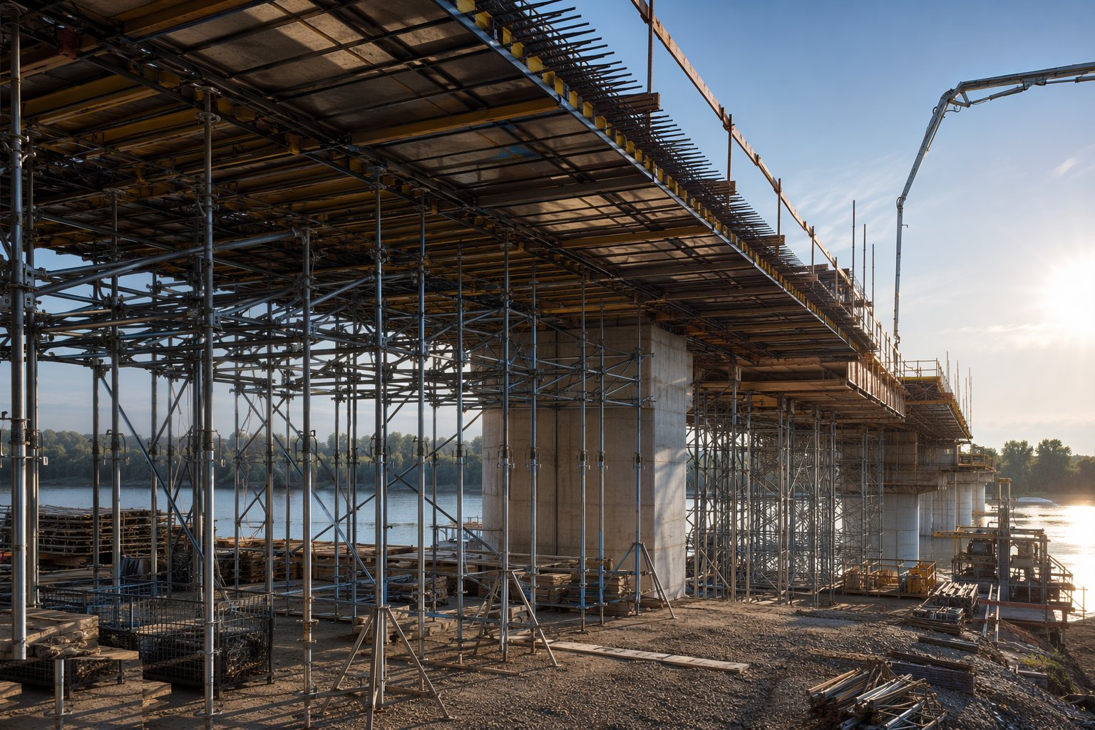
For in-situ decks, the falsework — props, frames, grillage beams on spreader foundations — is designed for the full weight of wet concrete plus construction loads, checked independently, and erected on ground that has been proven to carry it. Formwork follows: soffit panels set to camber, edge forms to profile, and access platforms for the pour crew. The Temporary Works Coordinator signs the permit to load before a bar of reinforcement goes on.
Step 3: Fix reinforcement, ducts and embedded items
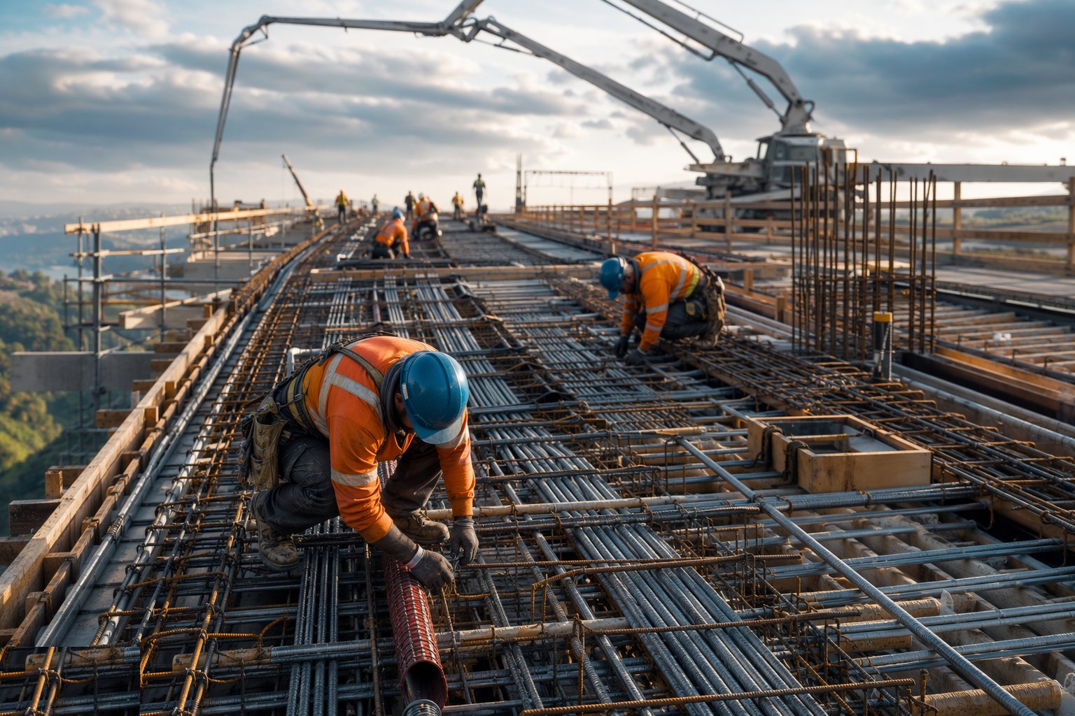
Fix the deck reinforcement to the drawings with specified cover — top mat supported on chairs that will not sink into the pour — and install post-tensioning ducts tied to their exact profile, with vents and grout inlets where the system requires. Embed everything that must be there before the pour: drainage outlets, joint reinforcement at the ends, parapet starter bars, earthing and any service ducts. A congested deck cage is inspected and signed off before the formwork closes.
Step 4: Cast and cure the deck concrete
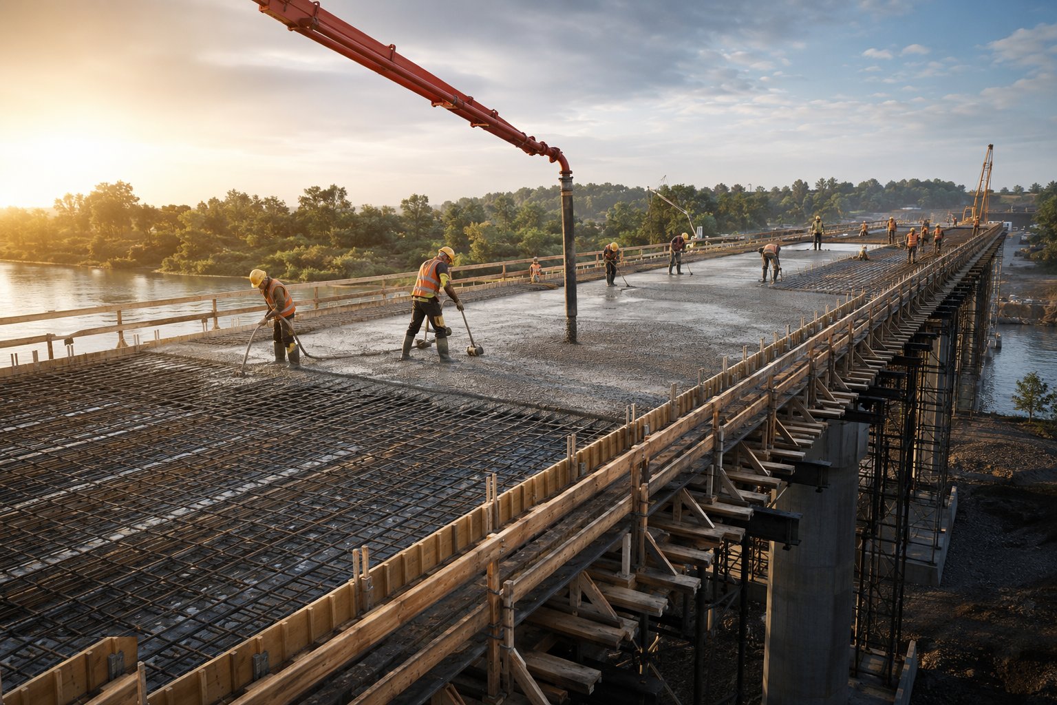
Pour in the planned sequence — for continuous decks this means spans before closure sections, with pour joints where the design puts them, not where the shift ended. Keep the pour continuous, vibrate systematically, and watch the falsework: settlement gauges or survey checks confirm it is behaving as designed. Curing starts immediately — hessian and water, curing membrane, or both — and in Gulf heat the pour is scheduled for night with chilled concrete and wind breaks against plastic shrinkage.
Step 5: Stress the tendons and grout the ducts
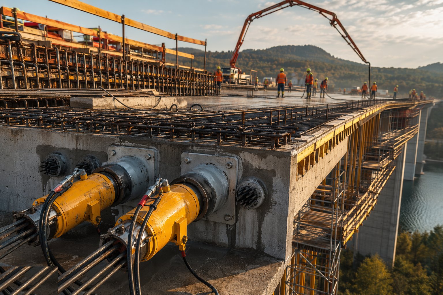
For post-tensioned decks, stress when the cubes or cylinders prove transfer strength: jacks calibrated, tendons stressed in the specified order, and every elongation recorded against the calculated value — out-of-tolerance extensions mean an investigation, not a shrug. Grout the ducts promptly after stressing with a bleed-tested grout mix, injected from the low end until clean grout flows from every vent. The stressing and grouting records go into the health and safety file; they are part of the asset.
Step 6: Strike and destress the temporary works
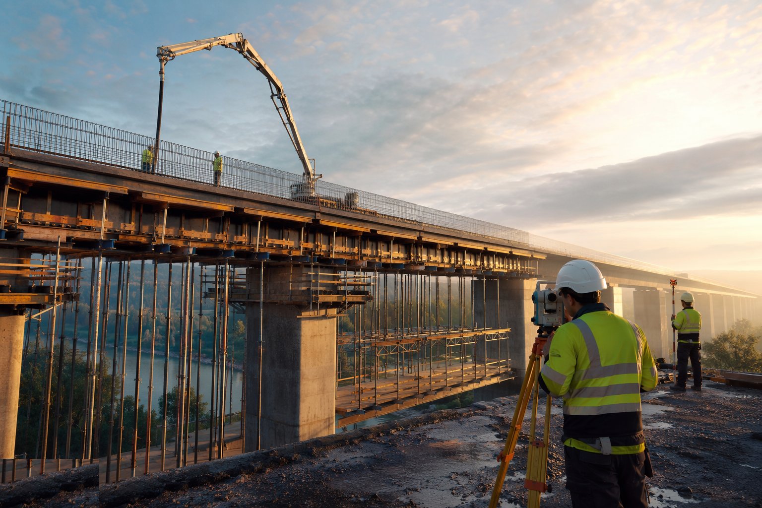
Remove formwork and falsework only when the concrete has the strength to carry itself plus the next loads — proven by cubes, not by the calendar — and in a sequence that transfers load gently: props eased and lowered progressively across a continuous deck so no span is shocked. Survey the deck profile immediately after destress: the actual camber is compared with the design, and any deviation is dealt with before the deck is built on.
Step 7: For beam decks: place, stitch and make continuous
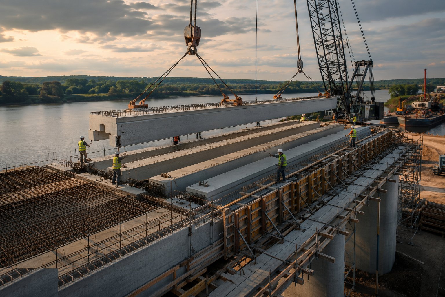
Precast beams are lifted from delivery or a laydown onto the bearings, braced immediately — a bare beam is unstable until restrained — and surveyed for line and level. Permanent formwork spans between beam flanges, the deck slab reinforcement is fixed, and the in-situ slab, end diaphragms and pier continuity concrete are cast in the designed sequence. Continuity pours over piers come last, turning simply-supported beams into a continuous deck that cracks less and rides better.
Plant and equipment
- Falsework systems: props, frames, grillage and formwork panels
- Crawler and mobile cranes for beams and materials
- Concrete pumps and placing booms; poker vibrators
- Post-tensioning jacks, pumps and calibration rigs; grout mixers and pumps
- Strand pushers and duct preparation equipment
- Curing equipment: bowsers, hessian, membrane sprayers
- Rebar cutters, benders and fixing tools
- Survey instruments for camber and profile control
Quality control checks
- Temporary works design check certificates and permit-to-load before loading falsework
- Concrete compliance: BS 8500 class, cubes/cylinders per pour, temperature records in hot weather
- Cover meter survey of the hardened deck; crack inspection and mapping
- Stressing records: force and elongation per tendon against calculated values, jack calibration current
- Grout fluidity and bleed tests; duct pressure or flow records per duct
- Deck profile and camber surveyed after destress against design
- Beam placement survey and bracing check before deck slab pours
Safety considerations
- Falsework collapse prevention: designed, checked, founded on proven ground, loaded by permit
- Work at height on deck edges: edge protection from the first operation, not after the pour
- Post-tensioning: exclusion zones behind live anchorages during stressing — a failed tendon is a projectile
- Concrete burns and dermatitis: gloves, wash stations, no kneeling in wet concrete
- Lifting plans for beams and plant; tag lines and banksmen on every lift
- Night pours: task lighting, fatigue management, pedestrian segregation
- Heat stress on Gulf summer pours: scheduling, hydration, shaded rest
Common defects
- Falsework settlement during the pour — camber lost, soffit profile wrong
- Plastic shrinkage cracking from wind and sun on an uncured deck surface
- Ducts displaced during concreting: tendons stressed to the wrong profile
- Voids in grouted ducts found years later by corrosion of the strand
- Honeycombing at congested anchorages and diaphragms
- Beams placed out of line, forcing a thick, heavy correction pour
- Deck struck early on optimistic cube results — permanent deflection locked in
Best suited for
- In-situ, precast-beam and post-tensioned decks
- Falsework and formwork spanning live obstacles
- Deck pours and stressing sequenced against creep, shrinkage and design load
- The span itself — where the design finally meets gravity
How long does Bridge Deck Construction take?
Typical duration: 8–16 weeks for a single-span deck; 6–12 months for a multi-span viaduct deck cast span by span, with stressing and grouting trailing each pour by about a week..