Bridge Erection Methods
How long spans actually get built when you cannot stand on the ground below — balanced cantilever, incremental launching, launching gantries and the heavy lifts.
Last updated 2026-07-28 by the BuildPedia Editorial Team.
What is Bridge Erection Methods?
When the gap below the deck is a river, a live motorway, a railway or a deep valley, conventional falsework is off the table and the erection method becomes a design decision, not a site decision. The structure is designed around how it will be built: segment lengths, tendon layouts and temporary stability are all fixed by the chosen method before a drawing is issued. Get the method wrong and the job is unbuildable; get it right and the deck grows out over the obstacle without ever touching it.
The two great self-supporting methods are balanced cantilever — building out symmetrically from each pier, either casting segments in place with travelling formwork or lifting precast segments and gluing them with epoxy — and incremental launching, where the deck is assembled behind an abutment and pushed out over the piers on temporary sliding bearings with a light steel launching nose at the front. Between them sit span-by-span erection on an overhead or underslung launching gantry, the method that built most of the world's metro viaducts, and the brute-force option: heavy crane lifts, sometimes tandem lifts of hundreds of tonnes, usually at night over a possession of whatever runs below.
In the UK, every significant lift is planned under BS 7121 with an appointed person, a written lift plan and LOLER thorough examinations on the crane; lifts over live railways or motorways go in under possessions or full closures agreed months ahead. In the UAE the same disciplines apply, and the scale is familiar: Dubai's metro viaducts were erected span by span with gantries and precast segments, with balanced cantilever reserved for the big road crossings, all executed beside some of the busiest roads in the region under RTA traffic management approvals.
When and why is Bridge Erection Methods used?
The erection method is chosen at design stage and executed once the substructure can receive it, because it dictates the segment design, the temporary works, the plant procurement and the programme of the whole structure. It matters because it is the highest-risk phase of bridge building: the structure passes through temporary configurations it will never see again, and a stability or lifting failure here is catastrophic, not repairable. There is no domestic version of a launching gantry or a balanced cantilever — the closest a small site gets is craning a precast garage or a steel kit over a garden wall, which borrows the BS 7121 lift-plan discipline (appointed person, ground checks, exclusion zone) if none of the glamour.
Types of Bridge Erection Methods
Balanced cantilever
Segments built out equally on both sides of a pier — cast in situ with travelling formwork, or precast units lifted and epoxy-jointed — each stressed back to the previous as it goes. The cantilevers meet at mid-span for a closure pour. It needs nothing below the deck, which is why it spans rivers, gorges and live roads, but stability is checked at every single stage, and a dropped segment is unthinkable.
Incremental launching
The deck is cast or assembled in sections behind one abutment and pushed forward with hydraulic jacks, sliding over temporary bearings on every pier, guided by a light launching nose that takes the front cantilever's bending. Straight or constant-radius decks only, and the friction and deflection are monitored on every push — but the whole deck is built at ground level, at one station, with factory discipline.
Span-by-span gantry erection
An overhead or underslung launching gantry spans between piers, holds all the precast segments of one span at once, and lets them be epoxy-jointed and stressed into a complete span before the gantry walks itself to the next. The production-line method for long viaducts — metros especially — where repetition makes the gantry's cost back many times over.
Heavy crane lifts
Whole spans, girders or pre-assembled units placed by very large cranes, sometimes two cranes in tandem. Simple in concept, ferocious in planning: ground bearing for the crane, rigging design, centre of gravity, exclusion zones, weather limits and — over live infrastructure — a possession booked to the minute. When the window is hours, the lift is rehearsed.
Bridge Erection Methods: step by step
Step 1: Fix the method and engineer every stage
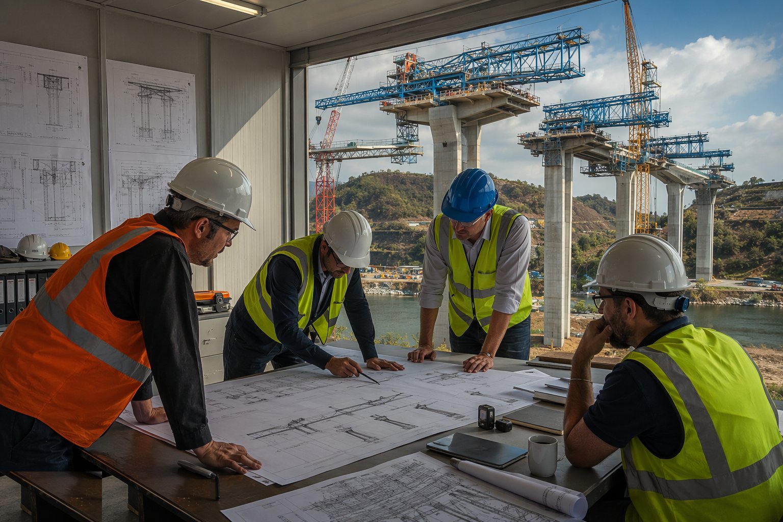
Confirm the erection method with the designer and run the stage-by-stage analysis: the structure at every intermediate configuration, with its temporary loads — wind on a half-built cantilever, the nose dipping at the next pier, a gantry carrying a full span. Temporary works to BS 5975 apply in full: travelling formwork, launching noses, temporary prestress and temporary bearings are all designed, checked and certificated. The method statement that comes out of this is the rulebook for the next year.
Step 2: Prepare the yard, casting cell or assembly bed
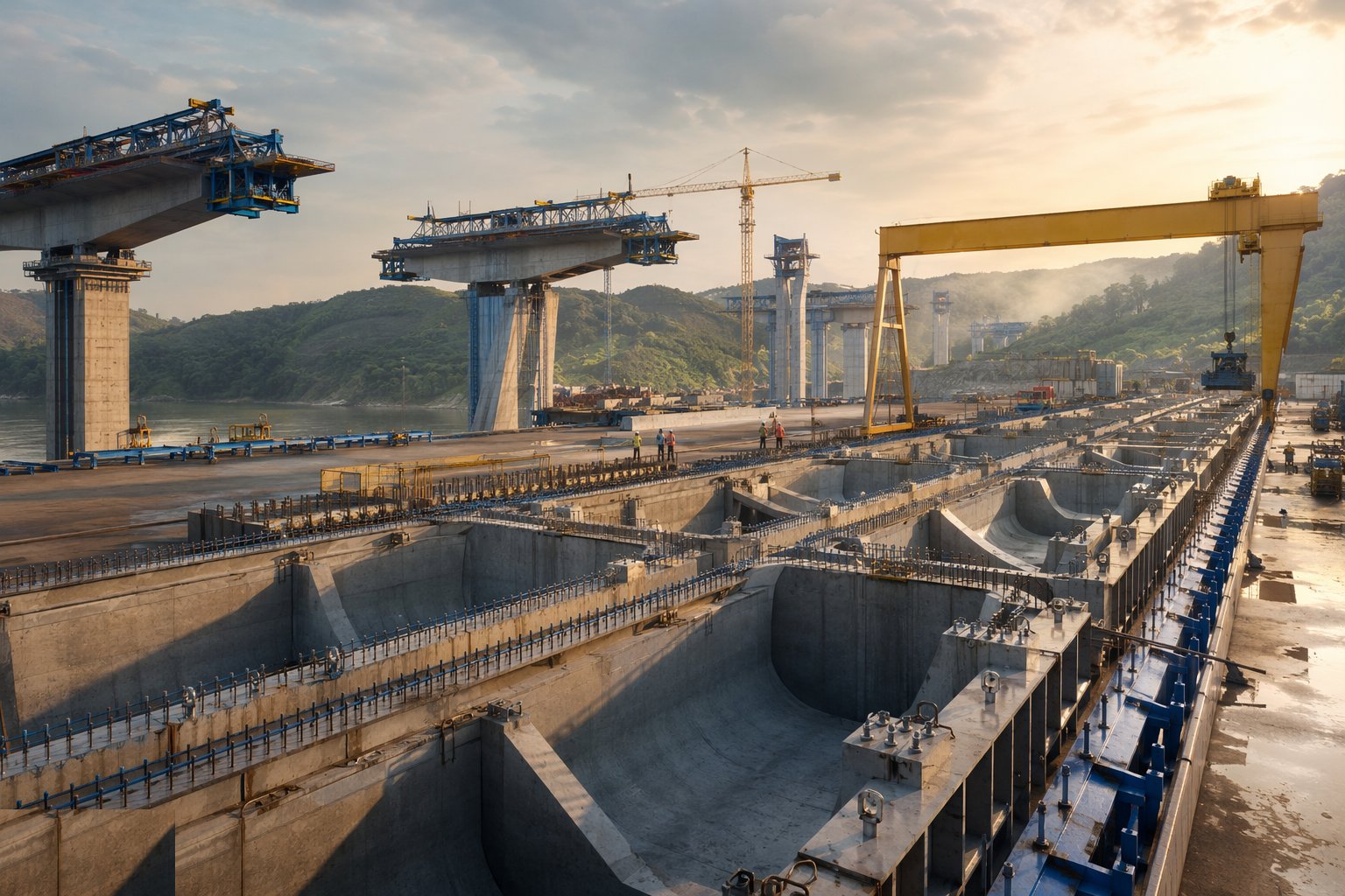
Set up where the structure will actually be made: the precast segment casting yard with its match-cast beds and curing arrangements, the in-situ casting cell behind the abutment for launching, or the crane platforms and laydown for heavy lifts. Survey control here is obsessive — match-cast segments only fit if every one is cast against the last, and a launched deck only lands on its bearings if every millimetre of the assembly bed is true.
Step 3: Build the cantilevers or launch the deck
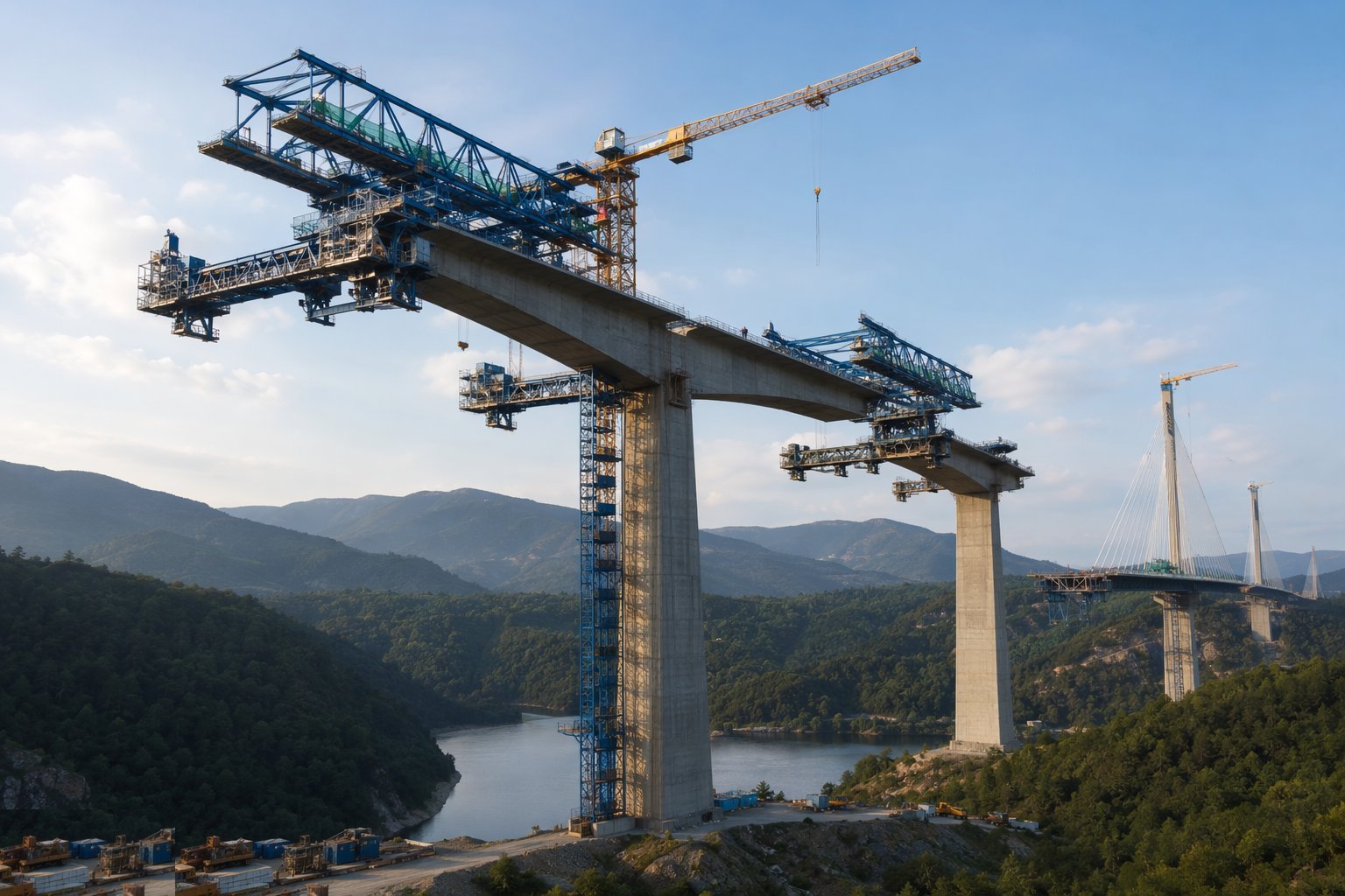
Balanced cantilever: erect the pier table (the first segment over the pier), then add segments in pairs, stressing each to the last and checking geometry after every pair — the cantilevers creep, and the survey tells you how much. Launching: assemble a section, push with the jacks at controlled pressure, monitor friction, deflection and the nose, then bolt on the next section and push again. Either way, progress is logged stage by stage against the predicted geometry; divergence is investigated, not averaged away.
Step 4: Run the gantry cycle, where used
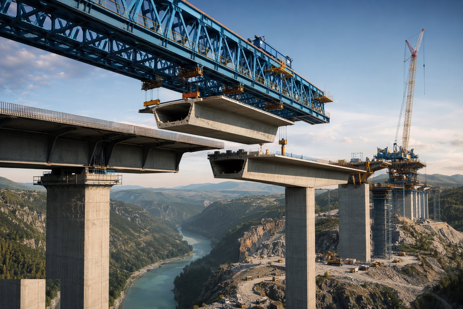
Feed segments to the gantry from below or along the completed deck, hang them in order, apply the epoxy to the match-cast faces and squeeze the joints with temporary prestress before it gels. Stress the span's tendons, transfer the load from gantry to bearings, and launch the gantry forward to the next span. The cycle repeats with a rhythm that sets the whole project's programme — a well-run gantry turns spans out like products.
Step 5: Plan and execute the heavy lifts
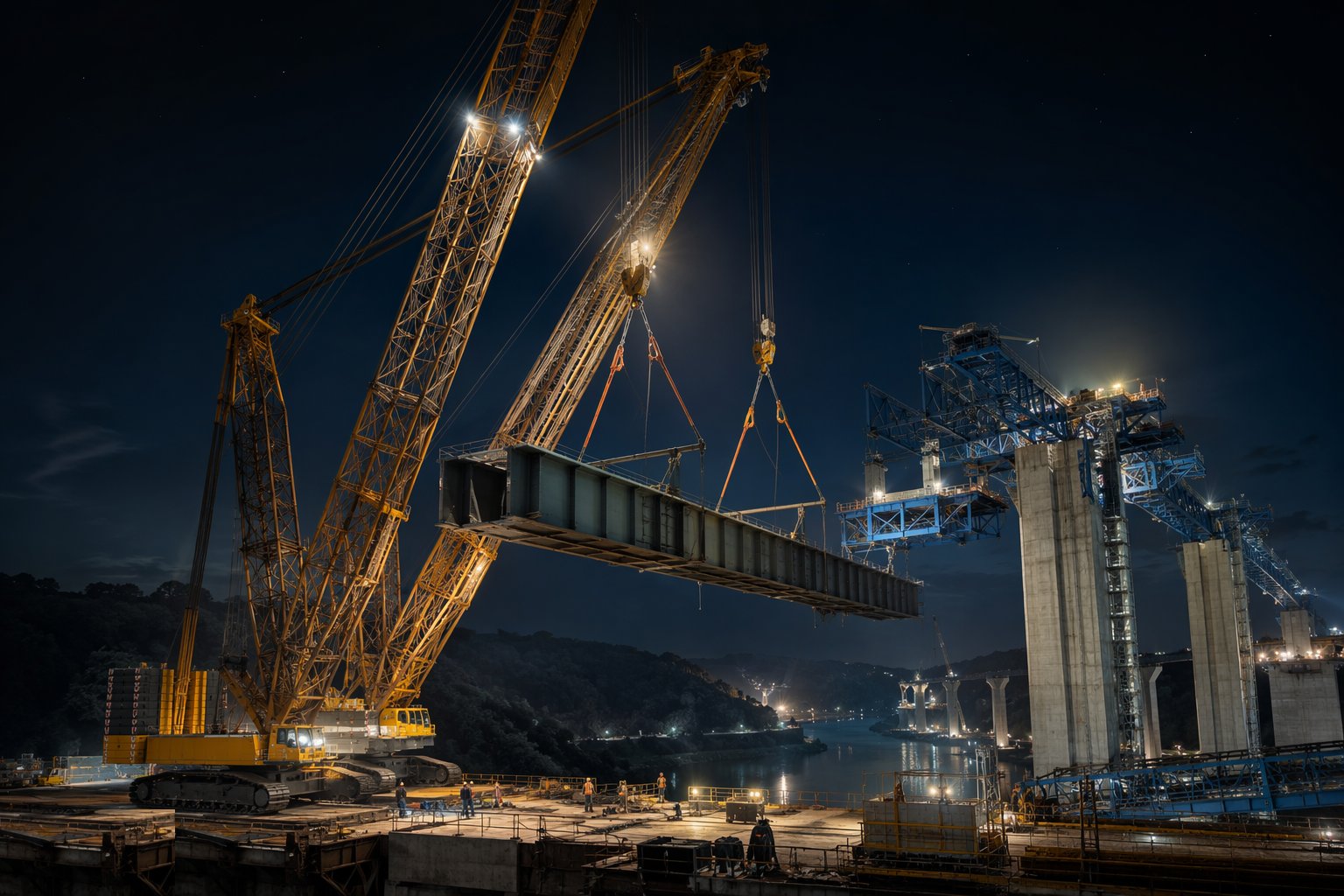
For crane erection: the appointed person produces the lift plan — crane selection and configuration, ground bearing proof and mats, rigging and centre of gravity, wind limits, exclusion zones, and the communication protocol for tandem lifts. Over live railways or motorways, the lift goes in under a booked possession with the road or line closed and protected. The load is trial-lifted and hung to check balance before it ever travels; once airborne it moves slowly, on tag lines, to its bearings.
Step 6: Close the structure and strike the temporary works
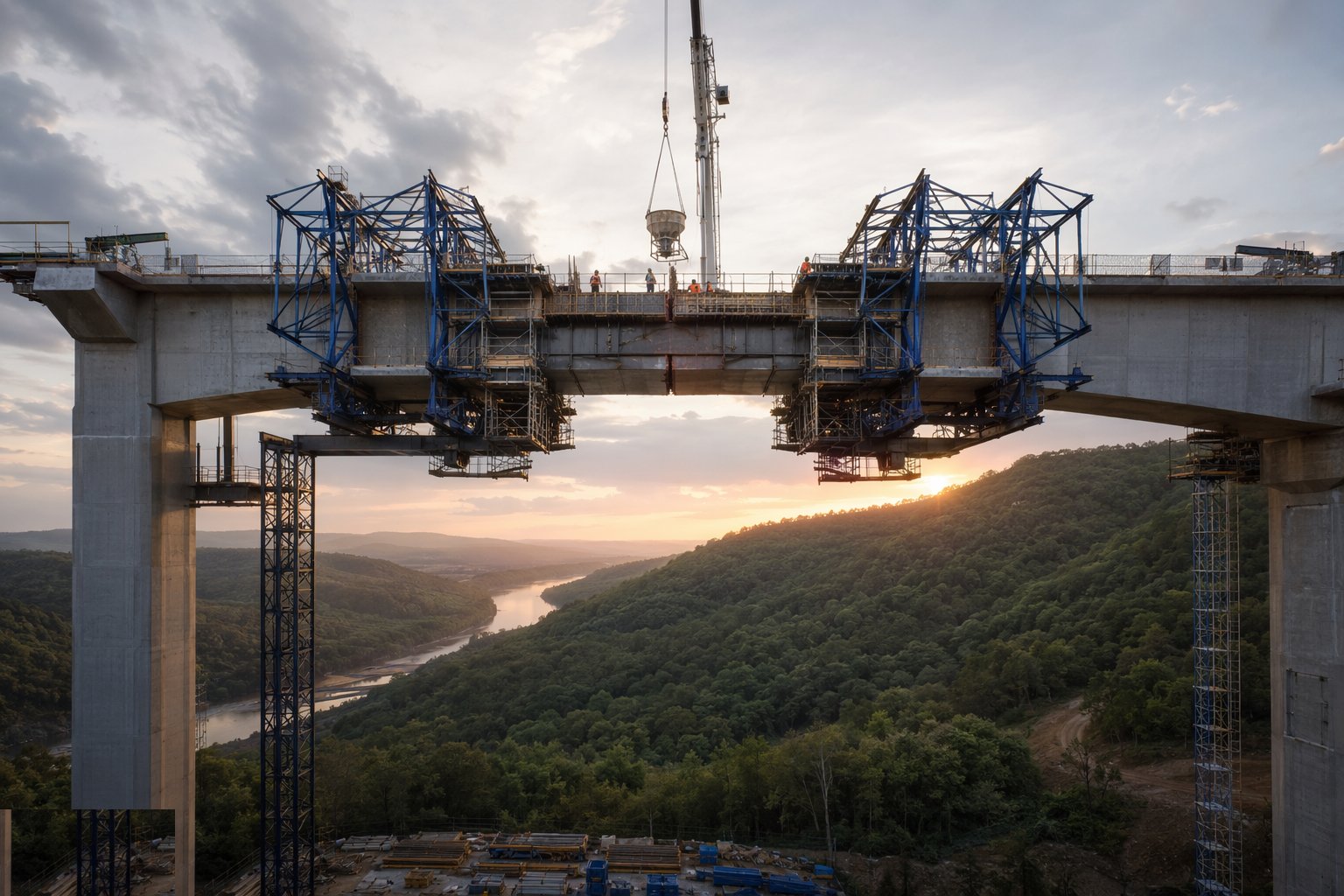
Cast the mid-span closures between cantilevers at the coolest part of the day so the joint is not prised open by afternoon heat; stress the continuity tendons that tie the structure into its final system. Remove the temporary prestress, temporary bearings, noses and travellers in the designed sequence, transferring load to the permanent bearings under survey control. Then verify the final geometry: profile, camber and bearing loads against the design model, and record the as-built for the health and safety file.
Plant and equipment
- Travelling formwork (form travellers) for cast in situ cantilevering
- Launching gantries: overhead or underslung, with segment handling gear
- Heavy crawler cranes (500 t and up) and tandem-lift rigs; modular trailers
- Hydraulic launching jacks, sliding bearings and launching nose
- Epoxy mixing and application equipment; temporary stressing bars
- Post-tensioning jacks and grout plant for stage stressing
- Survey: total stations, precise levels, automated monitoring prisms
- Temporary works: propping, grillage, crane mats and spreader beams
Quality control checks
- Stage-by-stage structural analysis signed off; deviations investigated against the model
- Match-cast segment dimensional records; epoxy batch and open-time control
- Geometry survey after every stage: cantilever deflection, launch alignment, gantry position
- Stressing and grouting records per stage, as for any post-tensioned work
- Lift plans approved by the appointed person; crane LOLER examinations and ground bearing proof
- Friction, jack pressures and nose deflection logged on every launch push
- Final as-built geometry and bearing load survey against the design model
Safety considerations
- Temporary stability of incomplete structures: wind limits, hold points between stages, no unauthorised loading
- Work at height over live traffic, water or railway: edge protection, debris netting, nothing dropped — ever
- Heavy lifts: exclusion zones, appointed person control, no one under a suspended load, weather cut-offs enforced
- Epoxy handling: chemical protection and ventilation in confined segment joints
- Stressing operations with exclusion zones behind anchorages at every stage
- Possession working at night: fatigue management, lighting, clear abort criteria and hand-back deadlines
- Gantry launching: interlocked controls, exclusion from the gantry travel path
Common defects
- Cantilever geometry drifting stage by stage — closure segments that will not meet
- Epoxy joints starved or gelled before squeeze: weak, leaky joints between segments
- Launch friction rising unnoticed — spalled sliding surfaces and a stalled push
- Crane platform bearing failure under outriggers on unproven ground
- Segments stored twisted or stacked badly: match-cast faces no longer match
- Continuity tendons stressed out of order, locking unintended moments into the deck
- Possession over-run because the lift was not rehearsed — the road opens late and the authority remembers
Best suited for
- Long spans built where nothing can stand below
- Balanced cantilever, incremental launch and launching gantry construction
- Heavy lifts over live railways, roads and waterways
- Possession-critical erection engineered to the hour
How long does Bridge Erection Methods take?
Typical duration: 6–18 months for a major cantilever or launched crossing; a gantry-erected viaduct typically achieves a span every one to two weeks once the cycle is established; individual heavy lifts are nights, preceded by months of planning..