Cooling Systems
Getting the heat out — chillers and chilled-water loops, CRAH units and aisle containment, free cooling, and the direct liquid cooling that high-density AI racks now demand, all measured by one number: PUE.
Last updated 2026-07-28 by the BuildPedia Editorial Team.
What is Cooling Systems?
Every watt of electricity a data centre consumes leaves the building as heat, and the cooling system is the machinery of that departure. A 50 MW facility is a 50 MW radiator that must never overheat; the cooling plant is sized, duplicated and controlled to hold the IT inlet temperatures within the band the server manufacturers warrant — while consuming as little energy as possible doing it, because every cooling watt is a watt not sold to a customer. That trade is captured in PUE — power usage effectiveness, the ratio of total facility power to IT power — a number the industry markets on, reports on, and designs backwards from. Modern facilities chase PUE figures around 1.2–1.4; older stock runs 1.6 and beyond.
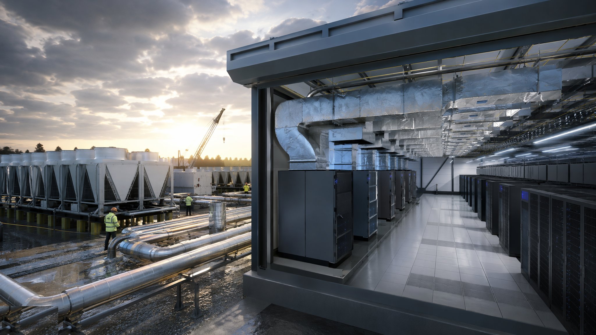
The traditional architecture is chilled water: central chiller plant — air-cooled or water-cooled — producing chilled water that circulates to CRAH (computer room air handling) or CRAC units around the data halls, which push conditioned air into the white space and draw hot air back. Air management decides whether that expensive cold air reaches the servers: hot aisle/cold aisle layouts with full containment — roofed and doored aisles that physically separate supply from return — have become the norm because mixed air is wasted energy. Where climate allows, free cooling does more and more of the work: dry coolers and economiser modes that reject heat to the air without running compressors, and adiabatic systems that pre-cool with evaporated water when ambient climbs — with the water consumption traded carefully against the energy saved, a real consideration in the Gulf where adiabatic systems fight 50 °C summer peaks and water is not free either.
The frontier is liquid. AI and high-performance computing racks now draw 30–130 kW per rack — beyond what air can move — and direct-to-chip liquid cooling (cold plates on the processors with coolant distribution units per row) and rear-door heat exchangers are arriving at scale, with immersion cooling at the specialist end. This changes the construction scope fundamentally: coolant loops, manifolds, CDUs and leak detection become first-fix services in the hall, the floor must be designed for heavier point loads and the consequences of liquid where liquid should never be, and the heat captured in liquid form is increasingly reused — exported to district heating schemes in European markets. In the UAE the conversation is dominated by ambient extremes: plant sized and derated for 50 °C design days, water-side chemistry managed hard, and redundancy sized so a chiller trip in August is an event the facility shrugs off.
When and why is Cooling Systems used?
Cooling infrastructure installs alongside the power works as first-fix heavy MEP — chiller plants, pumps, pipework and CRAH units in with the shell completion, containment and final air management with the fit-out — because the commissioning of the cooling chain is on the critical path to integrated systems testing, and thermal proving under load-bank heat is the only way to know the design works. It matters because cooling is the largest non-IT energy consumer in the building and the most common cause of capacity strandings: halls that cannot be fully populated because the cooling or the power margin ran out first. It also matters commercially and reputationally: PUE commitments are written into colocation contracts and sustainability reporting, and in markets like the UAE the cooling design is the difference between a viable facility and an uninsurable one.
Types of Cooling Systems
Air-based cooling (DX and CRAC)
Direct-expansion systems and computer room air conditioning units serving smaller facilities and edge sites: refrigerant circuits doing the work, simple and self-contained. Limited in scale and efficiency but resilient and familiar — the default below a few hundred kilowatts per hall.
Chilled-water systems
Central chiller plant — air-cooled, water-cooled with cooling towers, or district-cooling fed — circulating chilled water to CRAH units and fan walls in the halls. The hyperscale standard: efficient at scale, freely redundant in N+1 or 2N arrangements, and compatible with free-cooling economiser modes that run the compressors less each year.
Hot/cold aisle containment
The air-management layer that makes air cooling efficient: enclosed hot or cold aisles — roof panels, end doors, blanking plates in every empty rack U-space, sealed floor cutouts — forcing supply air through the servers and return air back to the handlers without mixing. Retrofitting containment to an uncontained hall is one of the cheapest PUE improvements in the industry.
Free cooling and adiabatic
Economiser modes that reject heat without mechanical refrigeration when ambient allows: dry coolers, air-side or water-side economisers, and adiabatic pre-cooling that evaporates water to depress incoming air temperature on peak days. In temperate climates free cooling carries most annual hours; in the Gulf it is a shoulder-season tool with adiabatic assist carefully water-accounted.
Direct liquid cooling
Cold plates on CPUs and GPUs with coolant distribution units moving heat to water loops — the architecture of AI-density racks that air cannot serve. Construction implications are serious: coolant manifolds and flexible connections in the hall, CDUs per row, leak detection, and commissioning regimes borrowed from process engineering rather than HVAC.
Immersion and rear-door systems
The specialist ends of liquid: single or two-phase immersion tanks where servers bathe in dielectric fluid, and rear-door heat exchangers that capture heat at the rack exhaust with chilled-water coils — a retrofit-friendly bridge between air-cooled halls and liquid-cooled racks.
Cooling Systems: step by step
Step 1: Fix the thermal design and redundancy model
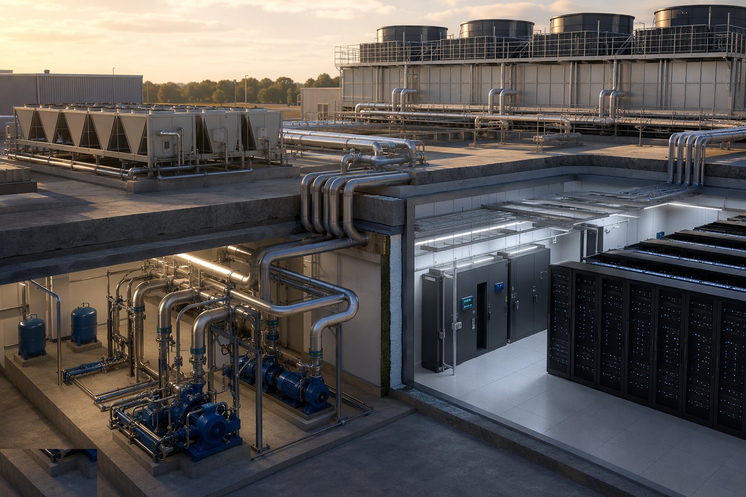
Set the numbers the plant is built to: IT load by hall and by phase, design ambient conditions (in the Gulf, the 50 °C summer design day is the one that sizes the plant), supply and return temperatures, PUE target, and the redundancy model — N+1 chillers, 2N loops, or distributed plant. Agree the failure scenarios the controls must survive: a chiller trip, a pump failure, a utility power loss mid-August. The thermal model of the halls — CFD analysis where the density warrants it — is validated against the containment and rack layouts before plant is ordered, not after.
Step 2: Install the central plant
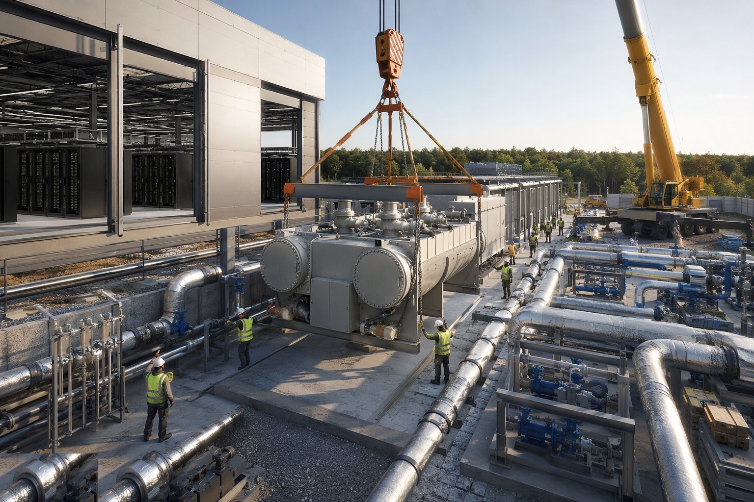
Set the chillers, dry coolers or cooling towers on their bases with vibration isolation, access for tube cleaning and the maintenance clearances the manufacturers demand — plant that cannot be maintained will not be. Install pumps, pressurisation, water treatment and dosing systems, and the pipework loops: welded or grooved steel for the mains, insulation and vapour sealing to keep condensation off cold surfaces, and the separation of redundant loops as physical as the electrical A/B trains. In the UAE, plant selection and derating for ambient extremes is verified against the design day, and tower or adiabatic water supply is a utility negotiation in its own right.
Step 3: Flush, fill and treat the water loops
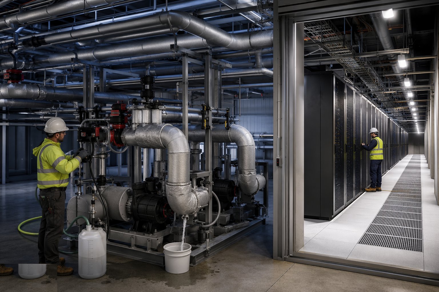
Before any CRAH unit or chiller is connected for duty, clean the loops properly: progressive flushing at velocities that move debris, chemical cleaning and passivation, side-stream filtration, and water chemistry established and dosed to the treatment specialist's regime — inhibitor levels, biocides, conductivity and pH logged from day one. Chilled-water loops that go into service dirty foul the CRAH coils and plate heat exchangers within a season, and the capacity loss is invisible until the hot day the facility cannot afford. Samples and chemistry records are part of the commissioning file, and the regime continues for the life of the plant.
Step 4: Install CRAH units, fan walls and hall air management
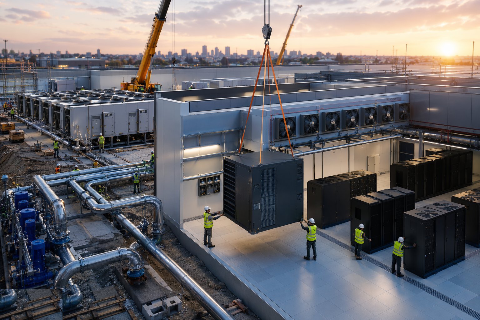
Position the CRAH/CRAC units or fan-wall arrays per the hall design, connect to the loops and power, and commission controls: supply air temperature and pressure control, valve and fan staging, and the BMS integration that lets the cooling chase the IT load. Fit the containment — aisle roofs, doors, blanking plates, brush seals at floor cutouts — and commission the air management: differential pressures between hot and cold zones, airflow balancing per row, and thermal surveys that find the bypass leaks the containment was built to stop. An uncontained gap over a rack is a short circuit for cold air, and it is found now with smoke and sensors, not later with alarms.
Step 5: Install liquid cooling infrastructure where specified
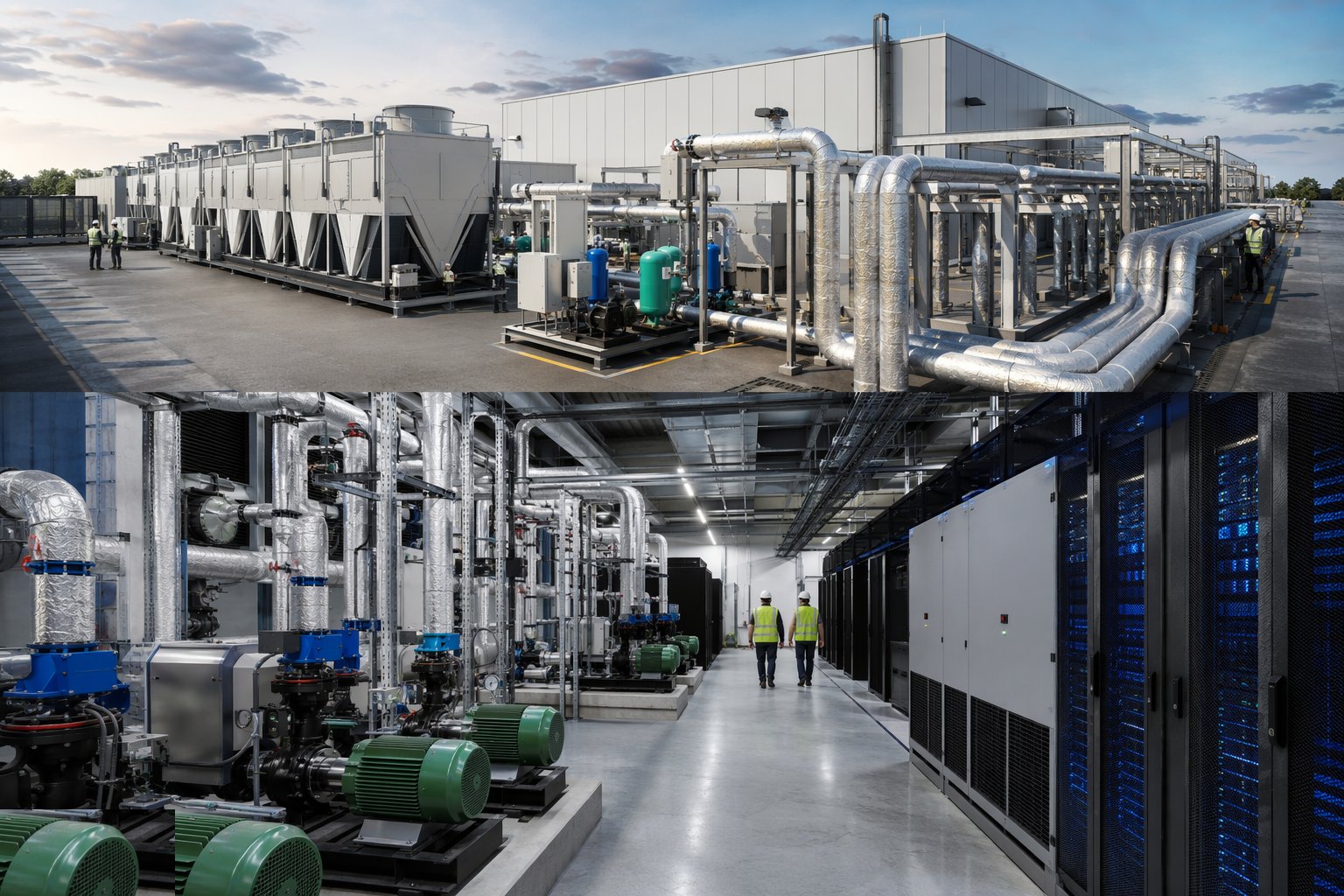
For direct-to-chip deployments, install the coolant loops as the process services they are: manifolds, CDUs, flexible connections to racks, leak detection cable along every route, and isolation valves that let a rack be disconnected without draining a row. Pressure-test every loop and connection before fluid introduction, fill and de-aerate under the coolant manufacturer's procedure, and commission the CDU controls against the IT equipment's requirements — flow rates, supply temperatures and the alarm and shutdown logic for a detected leak. The interfaces between the liquid system and the server vendor's hardware are documented connection by connection; this is the boundary where construction meets the client's own commissioning.
Step 6: Prove the system thermally under load
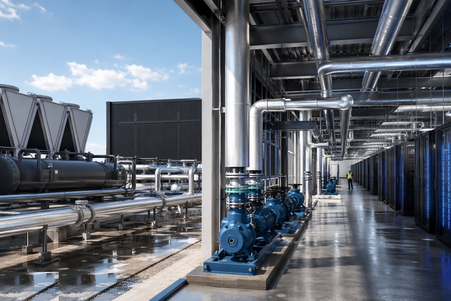
With load banks generating real heat in the halls, prove the cooling chain end to end: full-load runs at design ambient (or corrected to it), failure-mode testing — trip a chiller, kill a pump, open a loop valve — with the controls riding through, and thermal imaging of the halls to catch hot spots, bypass air and containment leaks. Verify the PUE instrumentation is metering what it claims to. Every test result feeds the integrated systems testing dossier, and a hall that cannot hold its temperature band under test load does not get handed over as ready for IT.
Plant and equipment
- Air-cooled and water-cooled chillers, dry coolers and cooling towers
- Primary/secondary pump sets, pressurisation and dosing plant
- CRAH/CRAC units, fan-wall arrays and in-row coolers
- Aisle containment systems, blanking plates and floor grommets
- Coolant distribution units, manifolds and leak-detection systems for liquid cooling
- Flushing rigs, side-stream filtration and water treatment test kits
- Load banks for thermal proving and thermal imaging cameras
- CFD-validated instrumentation: temperature/humidity sensor arrays and BMS integration kit
Quality control checks
- Thermal design and failure scenarios signed off, with CFD validation where density warrants
- Water loops flushed, chemically cleaned and dosed — chemistry logged from day one
- Chiller and CRAH factory witness tests and site commissioning records complete
- Containment integrity proven by pressure testing, smoke visualisation and thermal survey
- Liquid cooling loops pressure-tested and leak-detection verified before fluid introduction
- Full-load and failure-mode thermal testing passed before IT load is accepted
Safety considerations
- Refrigerant handling by certified engineers; pressure systems under permit and inspection regimes
- Chemical dosing and water treatment — COSHH controls, bunded storage, spill response
- Hot and cold surfaces: insulation and guarding on pipework through occupied areas
- Working in live or near-live halls — hot aisles are genuinely hot; access controls and heat stress management
- Liquid cooling: slip hazards from coolant leaks, dielectric fluids handled per their data sheets
- Heavy plant lifts — chillers and towers placed under engineered lift plans, often over live buildings
Common defects
- Loops commissioned dirty — fouled coils and heat exchangers eating capacity within a year
- Containment gaps: missing blanking plates, unsealed floor cutouts, doors propped open — cold air short-circuiting
- Plant derating ignored in Gulf design — the chiller that meets spec at 35 °C and not at 50 °C
- Water chemistry neglected through a long construction phase — corrosion products waiting for the first full load
- Leak detection installed but never functionally tested — the coolant leak discovered by the puddle
- Sensor arrays placed badly — the BMS controlling to temperatures nobody is experiencing
Best suited for
- Hyperscale and colocation halls chasing PUE commitments
- AI and high-density deployments requiring direct liquid cooling
- Retrofit efficiency programmes on existing uncontained halls
- Extreme-climate facilities where the design day is the business case
How long does Cooling Systems take?
Typical duration: Central plant and loops typically 4–8 months per phase; hall air management and containment with fit-out; thermal proving 3–6 weeks per hall within the commissioning window..