Data Hall Shell & Structure
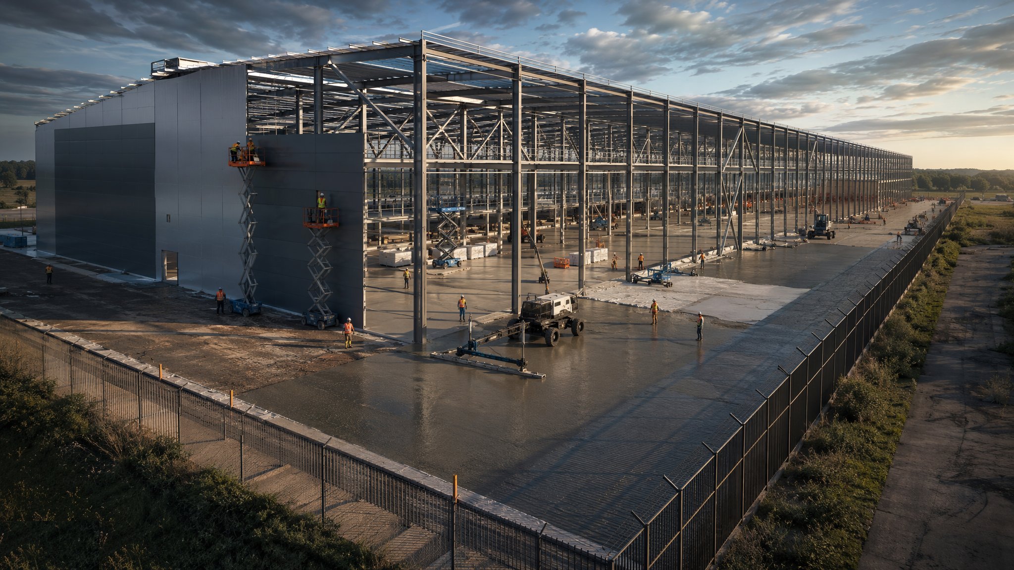
Long-span steel, high-load slabs and a secure, weather-tight envelope — the warehouse-scale structure engineered for rack loads, not roof lights, where weather-tightness is a hold point the whole fit-out depends on.
Last updated 2026-07-28 by the BuildPedia Editorial Team.
What is Data Hall Shell & Structure?
A data centre shell looks like a big shed and behaves like nothing of the sort. The data halls are long-span volumes — clear spans of 20 to 40 metres so rack rows never meet a column — under a steel frame designed for services density rather than people. The floor is the structure that does the real work: ground-bearing or suspended slabs engineered for rack loads that routinely run 10–20 kN/m² and climb well beyond that for high-density AI deployments, with surface regularity tight enough that raised floors and containment align across hundreds of metres. Columns, if they exist in the hall at all, land on a grid agreed with the rack layout at design stage and never move afterwards.
The slab is a production line in itself. Pour strategy is planned around laser screeds — large, continuous bays poured to tight level and flatness tolerances, with armoured joints, controlled mix designs and curing regimes that prevent the curling and cracking that would telegraph into the raised floor above. In the UAE, hot-weather concreting rules apply in full: chilled mixes, night pours in summer, curing discipline, because a slab that cracks or curls in a data hall is not cosmetic — it is a rack-alignment and airflow-containment defect. Where halls are stacked — multi-storey facilities are increasingly common on constrained sites — the suspended slabs carry the same loads with vibration and deflection limits the rack manufacturers and the cooling design care about.
Then there is the envelope, which does two jobs ordinary sheds never ask of it. The first is security: the shell is the outermost layer of a physical security stack that ends at the rack, so walls, roofs, doors and dock arrangements are designed to a security rating — blast resistance and stand-off where the threat assessment demands it, no unnecessary openings, and controlled vehicle interfaces. The second is absolute weather-tightness: the fit-out that follows is millions of pounds of electrical and IT equipment, and the shell must be provably watertight before any of it lands. Weather-tightness is a certified hold point on a data centre, tested and documented, not a hope.
When and why is Data Hall Shell & Structure used?
The shell and structure runs at the front of the programme and sets the ceiling on everything after it — the power and cooling plant sizing assumes the hall volumes, the rack layout assumes the column grid, and the fit-out cannot start until the envelope is certified weather-tight. It matters because the structural decisions are effectively irreversible: a floor that under-delivers on load capacity caps the facility's density for its life, a column in the wrong place fragments rack rows and airflow containment forever, and a leaky envelope discovered during fit-out damages the most expensive equipment on the project. For hyperscale and colocation clients the shell is also a replicable product — designed once, repeated across campuses — so the details are engineered for repeatability, speed and certainty, not bespoke expression.
Types of Data Hall Shell & Structure
Single-storey long-span halls
The classic hyperscale typology: portal or trussed steel frames spanning clear across the hall, ground-bearing high-load slabs, and plant yards on the roof or at grade. Fast to build, easy to replicate, and the default where land allows.
Multi-storey facilities
Stacked data halls on suspended slabs — common in land-constrained urban markets and much of the Gulf and Asia. Suspended high-load slabs with deflection and vibration limits, vertical riser strategy for power and cooling, and freight logistics sized for transformers and chillers moving to upper floors.
Ground-bearing high-load slabs
Thick, heavily reinforced slabs cast on prepared subgrade, poured in large bays under laser screed control to FM-class flatness, with armoured joints and often post-tensioning where spans or loads demand. The rack rows, the raised floor and the containment all take their line and level from this surface.
Secure and hardened envelopes
Shells engineered to a physical security standard: reinforced concrete or rated panel walls, blast resistance and vehicle stand-off where the threat assessment requires, ballistic-rated elements at sensitive interfaces, and no uncontrolled openings. Dock levellers, sally ports and search bays are part of the shell design, not afterthoughts.
Rooftop and yard plant platforms
The structure that carries the cooling and electrical plant: steelwork and slabs designed for chillers, dry coolers, generators and fuel tanks with their maintenance, vibration and replacement logistics designed in — a generator that cannot be swapped out in fifteen years is a design failure wearing a hard hat.
Data Hall Shell & Structure: step by step
Step 1: Freeze the grid, loads and tolerances
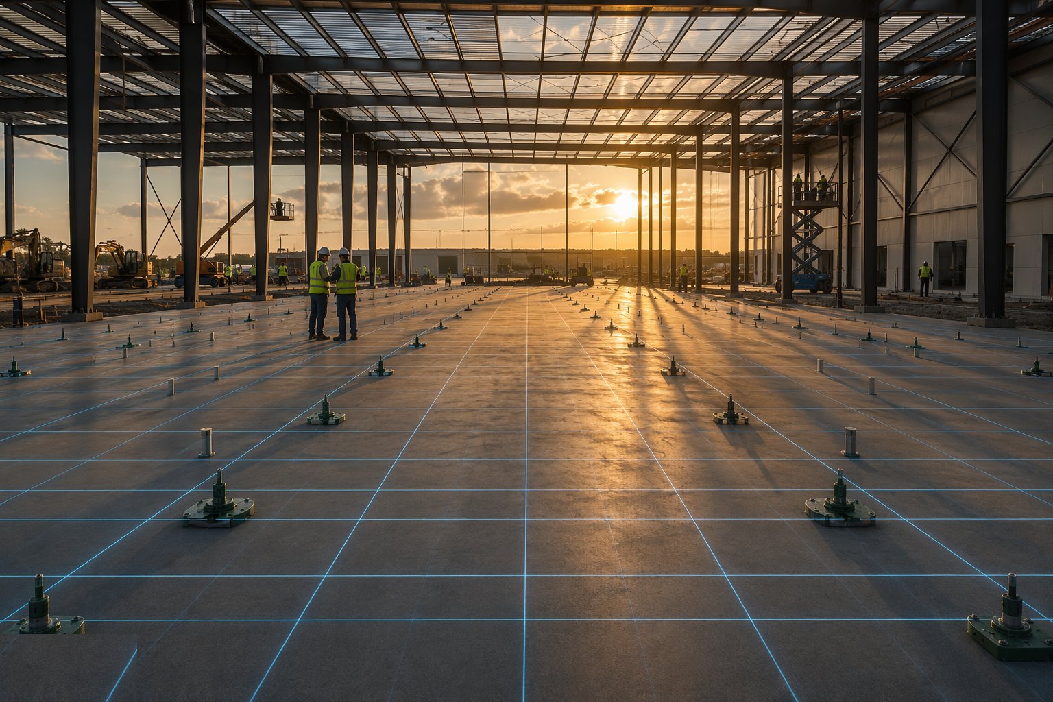
Before steel is ordered, lock the parameters the whole building inherits: column grid matched to the rack layout, floor load ratings by zone (data hall, corridor, plant), slab flatness and levelness classes, clear heights under structure and services, and the security rating of the envelope. These flow from the client's IT load density roadmap — a hall designed for 10 kW racks that later needs 50 kW liquid-cooled rows is a hall being structurally re-examined mid-life. Get the client's signature on the numbers, because every trade afterwards prices to them.
Step 2: Prepare the subgrade and pour the slab
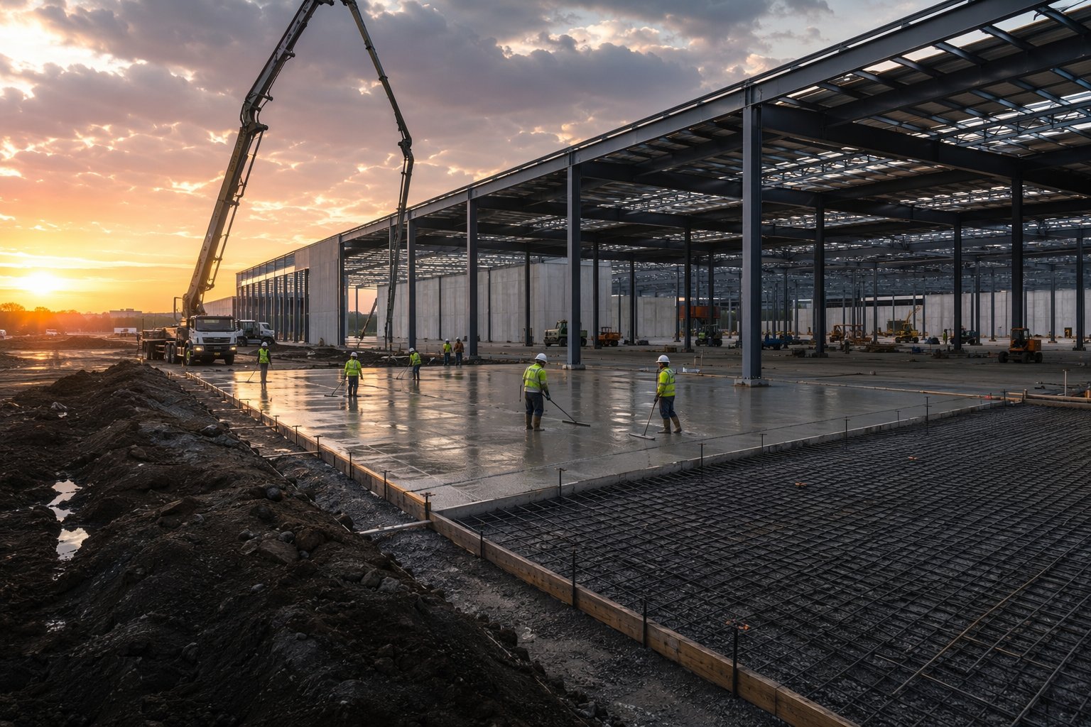
Prove and prepare the formation to the slab design, lay damp-proofing, insulation and reinforcement, and pour in large planned bays: continuous supply, laser screeds striking off to flatness, armoured or sawn joints on the agreed layout, and curing that survives the climate — curing compounds and early saw-cutting in UK damp, chilled night pours and ruthless curing discipline in Gulf heat. Test flatness and levelness as the bays cure, not at the end: a bay out of tolerance is ground and rectified while it is still one bay's problem. Where post-tensioning is used, stress and grout on the engineered sequence and record every duct.
Step 3: Erect the long-span frame
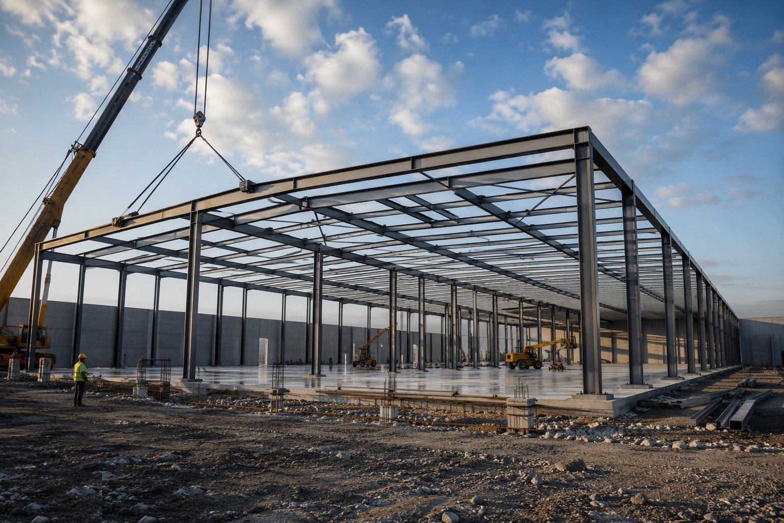
Fabricate and erect the steelwork to BS EN 1090-2 with the execution class the design calls for: portal frames or trusses lifted in pre-assembled sections where craneage allows, connections torqued and tagged, alignment surveyed before decking. Fire protection follows the design — intumescent or board — applied to the specification with dry film thickness verified. On multi-storey frames, hold the alignment and floor-to-floor tolerances hard; risers and containment on ten floors inherit every millimetre of wander from the frame.
Step 4: Build the secure envelope
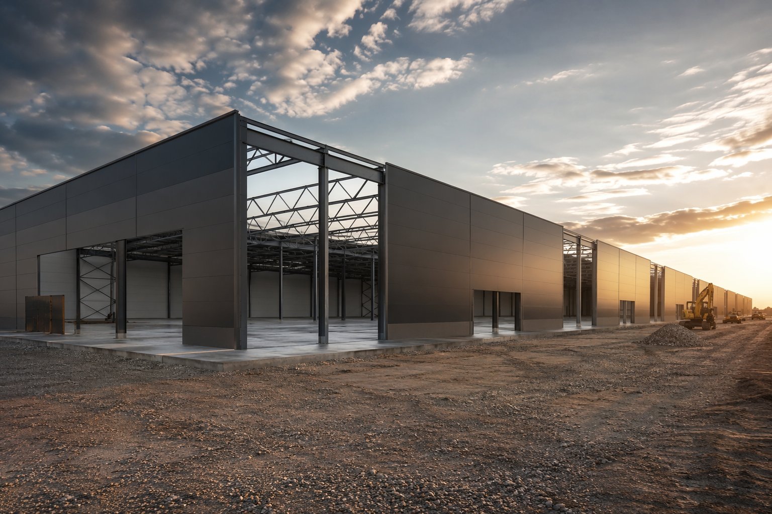
Clad the frame to the security and thermal design: rated wall and roof systems, controlled openings only, security-rated doorsets and dock arrangements, and stand-off and blast measures where the assessment calls for them. Coordinate every penetration — the envelope will be crossed by power, cooling, fuel and data, and each crossing is detailed, sealed and secured once, at shell stage, rather than ad hoc during fit-out. Perimeter works — fencing, vehicle barriers, search bays — are part of the same security layer and are built to the same standard.
Step 5: Prove weather-tightness and certify the hold point
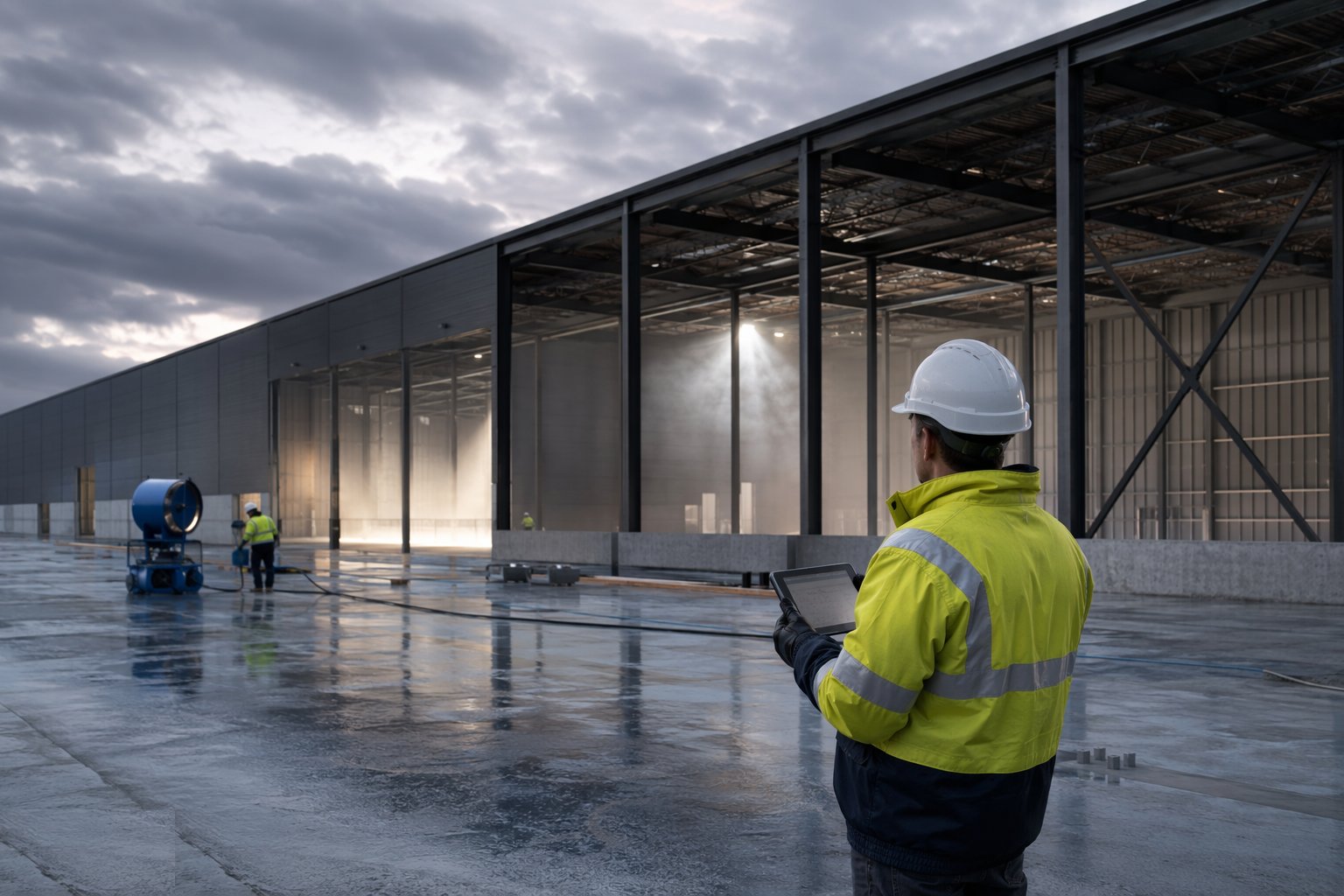
Before any fit-out material lands, prove the envelope: hose or flood testing of roof and wall systems where specified, thermal imaging or moisture surveys of the envelope, and a documented weather-tightness certificate signed by the envelope contractor and accepted by the client. Drainage, falls and overflow provisions are tested at the same time — a data hall cannot tolerate a single roof leak over a live rack row, so the shell is proven to a standard a warehouse never sees. Only when the certificate is signed does the hall hand over to fit-out.
Step 6: Protect the slab and shell through fit-out

The finished shell becomes the fit-out's factory floor: protect the slab from point loads and spills, control penetrations through the envelope under permit, and maintain the security regime as hundreds of workers arrive. Any structural openings cut during fit-out — and on a data centre there will be some — go through the structural engineer, the security design and the weather-tightness regime, because the shell's three functions (load, security, weather) are all still live duties until handover.
Plant and equipment
- Laser screeds and ride-on power floats for large-bay slab pouring
- Concrete pumps and continuous-supply batching for mass slab pours
- Heavy crawler and mobile cranes for long-span steel erection
- Torque-controlled bolting equipment and alignment survey instruments
- Armoured joint systems, saw-cutting equipment and curing sprayers
- Elevated work platforms and edge-protection systems for frame and envelope works
- Hose/flood test rigs and thermal imaging for weather-tightness verification
- Floor flatness (F-number/straightedge) survey equipment
Quality control checks
- Column grid, load ratings and flatness classes signed by the client before fabrication
- Slab bays tested for flatness and levelness as they cure, with rectification records
- Steelwork to BS EN 1090-2 with connection torque records and alignment surveys
- Fire protection dry film thickness verified across the frame
- Envelope penetrations logged, sealed and security-reviewed at shell stage
- Weather-tightness certificate signed before fit-out is permitted in the halls
Safety considerations
- Steel erection at height: planned lifts, exclusion zones, fall protection and edge protection throughout
- Large concrete pours: pump line safety, formwork/falsework checks and continuous-pour fatigue management
- Hot-weather concreting in the Gulf: heat stress management, night working lighting and rotated crews
- Heavy plant and cranage around a constrained shell footprint — segregation and lift planning
- Security regime from shell completion onwards: access control and vetting as the fit-out workforce grows
- Enclosed hall works: ventilation, dust control and emergency arrangements for a building-sized box
Common defects
- Slab flatness missed and discovered at raised-floor stage — grinding and self-levelling across hectares of floor
- Columns landed off the agreed grid — rack rows and containment fighting the structure for the building's life
- Slab curling and cracking from poor curing — joints pumping under rack loads
- Envelope penetrations cut ad hoc during fit-out — the weather-tightness certificate quietly voided
- Fire protection skipped or thin on concealed steel — found at inspection, recoated at height
- Plant platforms under-designed — the chiller replacement in year twelve that cannot be lifted out
Best suited for
- Hyperscale and colocation data halls at warehouse scale
- Multi-storey urban facilities on constrained sites
- Facilities with security-rated envelopes (government, financial, defence-adjacent clients)
- Campus developments where a proven shell design is replicated across phases
How long does Data Hall Shell & Structure take?
Typical duration: Typically 4–9 months from slab start to weather-tight certificate for a single large hall building, depending on scale, storeys and envelope rating; multi-hall campuses phase hall-by-hall..