Power Infrastructure
From utility intake to the rack PDU — substations, HV/LV switchgear, UPS and batteries, standby generators and busway distribution, engineered to a redundancy philosophy that tolerates failure without dropping a single server.
Last updated 2026-07-28 by the BuildPedia Editorial Team.
What is Power Infrastructure?
A data centre is a factory whose raw material is electricity. The power chain runs from the utility intake — often at 11 kV or 33 kV, in dedicated substations on the site — through transformers, HV and LV switchgear, UPS systems with their battery autonomy, and out to the racks via busway or cable distribution, with standby generators and fuel systems standing behind the lot. Every element is duplicated or distributed according to a redundancy philosophy the client chose at concept stage: N+1 (one spare of everything), 2N (two complete, independent systems), or distributed redundant (multiple systems sharing the load such that any one can fail). The philosophy is not a badge — it dictates how many substations, how many generator sets, how the switchboards are split, and how the whole thing can be maintained without ever de-energising the IT load.
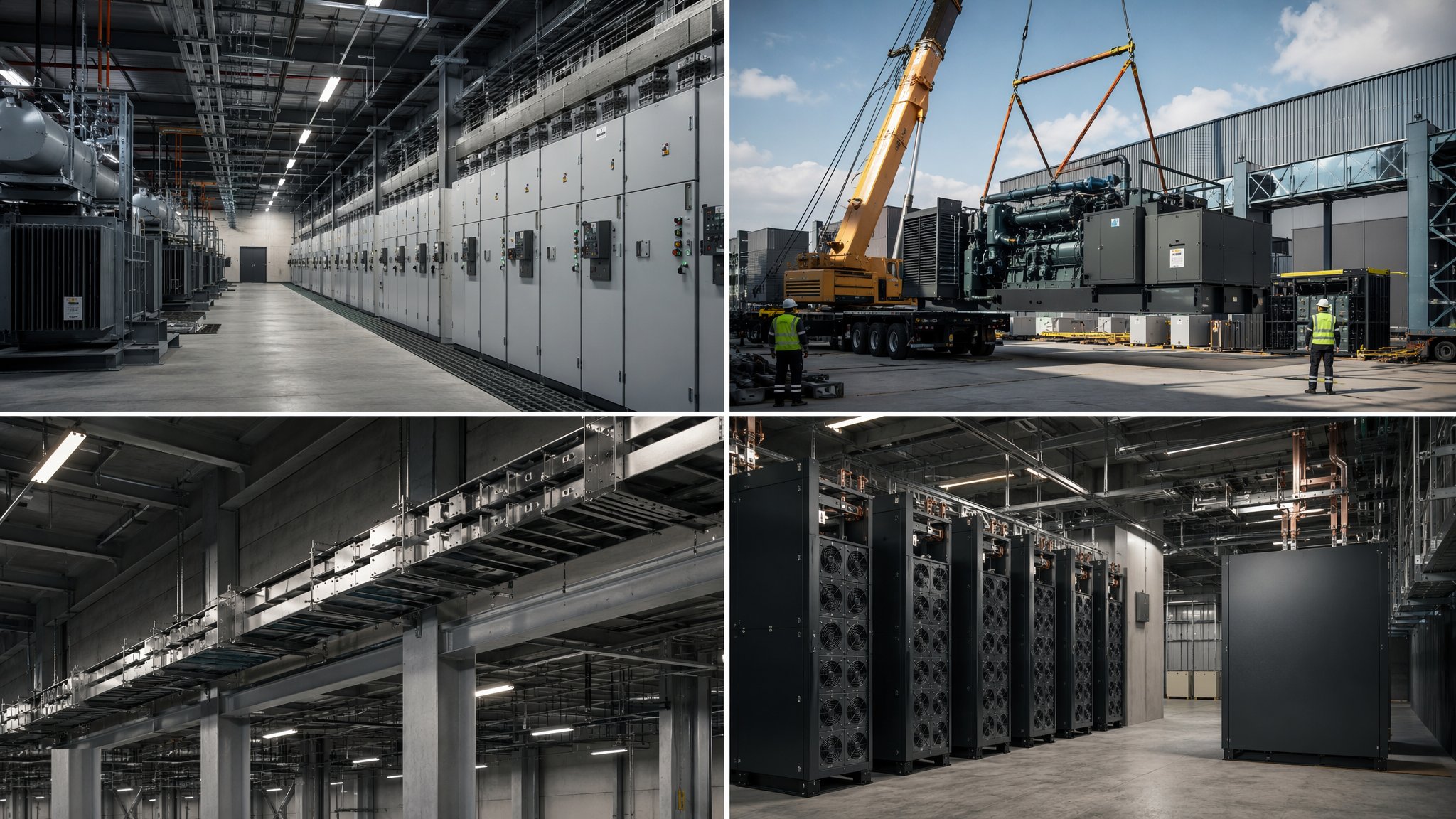
The scale is what separates this from ordinary electrical installation. A large facility takes a utility connection measured in tens or hundreds of megawatts; in the UK that means early, hard negotiation with the distribution network operator, and in the UAE, DEWA or the emirate's utility load approvals that gate the entire programme — power availability is frequently the site-selection decision. On site, the electrical rooms are industrial: cast resin or oil transformers in fire-rated cells, HV switchgear with arc-flash management, LV switchboards the length of a street, UPS halls with valve-regulated or lithium battery strings on rated floors, and generator farms with bulk fuel storage, day tanks and polishing systems to keep diesel viable for years of standby.
Distribution to the white space has its own technology. Overhead busbar trunking (busway) with tap-off units at each rack row has displaced much traditional cabling for flexibility — racks move, loads grow, and busway tap-offs move with them. Remote power panels, rack PDUs, static transfer switches for dual-corded equipment, and the earthing and protection coordination that lets a fault clear locally without tripping a megawatt of switchboard — all of it is designed, installed and then proven under load-bank testing before a single server is trusted to it.
When and why is Power Infrastructure used?
Power infrastructure is the longest-lead, earliest-started element of a data centre build — utility agreements and transformer orders run on lead times measured in years, not months, and the energisation sequence with the utility is a programme gate that commissioning depends on absolutely. It matters because the power chain defines the facility's product: a colocation client is buying availability, and availability is the redundancy philosophy made physical — a 2N facility can lose an entire electrical train and not drop a rack, but only if every breaker, cable route and control interlock was installed exactly as the single-line diagram says. It also matters because the testing that proves it — factory witness tests, site acceptance tests, load-bank runs and ultimately integrated systems testing — cannot be compressed at the end; the infrastructure earns its certification kilowatt by kilowatt.
Types of Power Infrastructure
Centralised UPS topology
Large central UPS halls feeding the whole facility or hall: monoblock or modular UPS frames with centralised battery rooms, static bypass and wrap-around maintenance bypass. Efficient at scale and simple to maintain, with the battery autonomy — typically 5–15 minutes at full load — bridging the gap until generators are on and stable.
Distributed UPS topology
Smaller UPS modules distributed per hall, per row or per rack, closer to the load. Granular failure domains and incremental capacity expansion, at the cost of more units to maintain — the choice is driven by the client's redundancy model and phasing strategy.
Diesel standby generation
The incumbent: multiple diesel generator sets in N+1 or 2N arrangements with bulk fuel storage, day tanks and fuel polishing. Proven, dispatchable and understood by every authority — with fuel resilience (typically 24–72 hours on site) sized to the client's risk appetite and the utility's reliability record.
HVO and gas generation
Lower-carbon alternatives gaining ground: HVO (hydrotreated vegetable oil) as a drop-in diesel substitute cutting lifecycle emissions, and gas gensets or combined heat and power where grid gas allows. Both trade off fuel logistics and runtime certification against sustainability commitments the operators increasingly sign up to.
Busway distribution
Overhead busbar trunking running the length of the data halls with plug-in tap-off boxes at rack rows — reconfigurable, measurable and fast to extend, versus fixed cable runs to remote power panels. The tap-off units carry metering that feeds the DCIM, giving per-row power visibility from day one.
Redundancy philosophies
The design doctrine the hardware serves: N (just enough), N+1 (enough plus one), 2N (two full mirror systems), 2(N+1), and distributed redundant (three or more systems, any one spare). Uptime Institute Tier classifications hang off these choices — Tier III demands concurrently maintainable, Tier IV fault-tolerant — and the certification, where pursued, audits the physical reality against the claim.
Power Infrastructure: step by step
Step 1: Secure the utility connection and design approvals
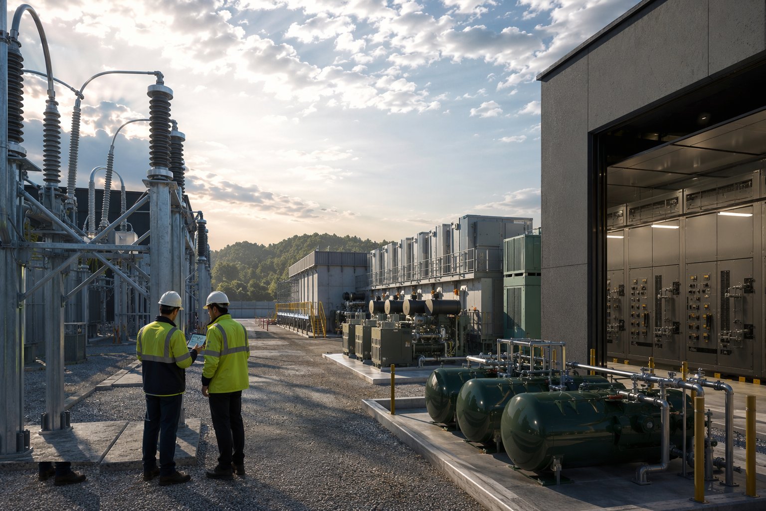
Start with the megawatts: negotiate the utility connection agreement with the network operator — UK DNO or DEWA/ADDC in the Emirates — including capacity, phasing, fault levels and the energisation programme, because the utility's own works are on your critical path and their programme is theirs, not yours. Get the authority approvals for substations, fuel storage and generator installations; fuel stores carry environmental and fire approvals of their own (Civil Defence in the UAE, environmental permitting in the UK). Every downstream date hangs off this step, and slippage here is bought back nowhere.
Step 2: Build the substations and electrical rooms
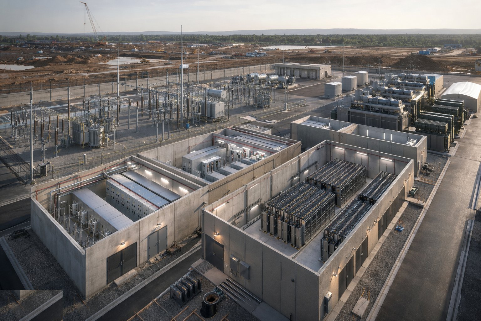
Construct the intake substations, transformer compounds and electrical rooms to the utility's and the design's standards: fire-rated cells, oil containment for oil-filled transformers, ventilation and cooling sized for the losses, cable containment routes kept clean of other services, and floors rated for the point loads — a transformer or a fully populated switchboard is a heavy lift with a permanent address. Blast and arc-flash considerations go into the room design where the fault levels demand them. Get the rooms weather-tight and secure early; the switchgear that arrives is the longest-lead, most damage-sensitive equipment on the project.
Step 3: Install HV/LV switchgear and transformers
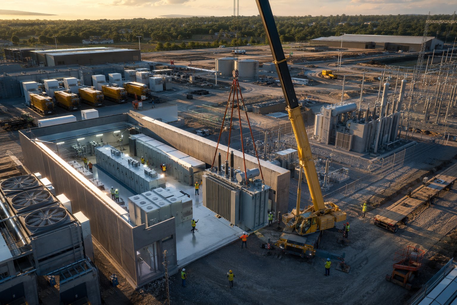
Set the transformers on their plinths with containment and cooling, install HV ring main units and the LV switchboards on their engineered bases, and terminate the HV cabling with certified jointers under test regime. Protection settings and grading are engineered, injected and signed off by the protection engineer — a board that trips upstream instead of downstream converts a local fault into a facility event. Every termination, torque and test is recorded; in 2N designs the physical separation of the A and B trains — separate rooms, separate routes, separate fire compartments — is verified as built, not assumed from drawings.
Step 4: Install UPS systems and battery plant
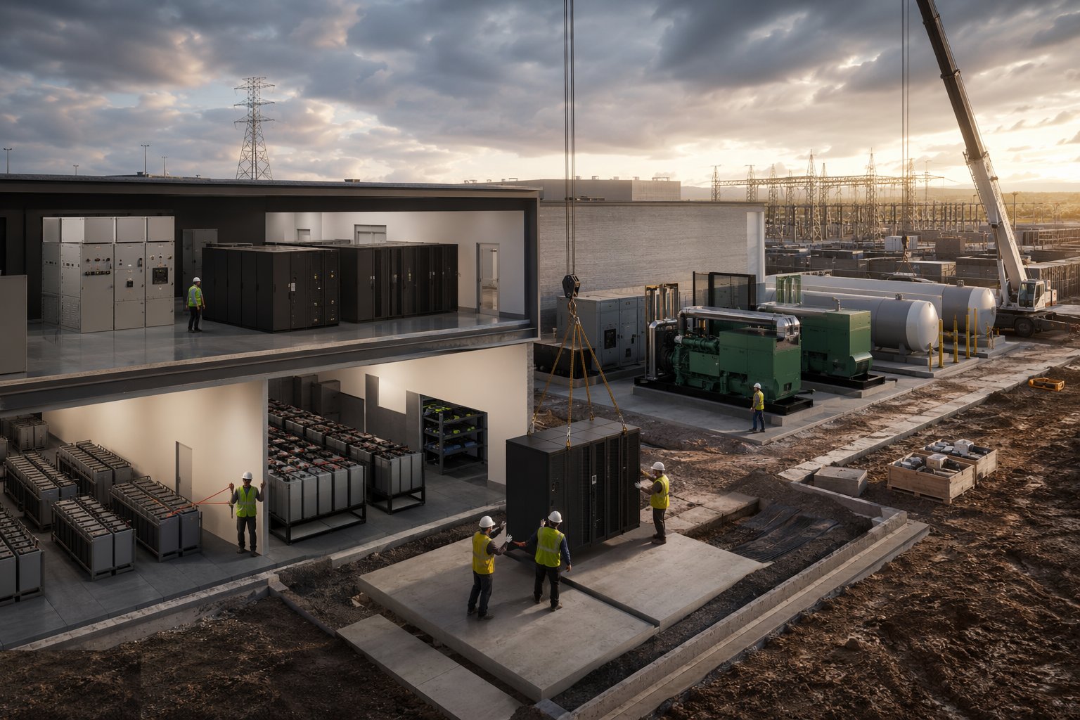
Install the UPS frames, static and maintenance bypass arrangements, and the battery strings — VRLA on open racks or lithium-ion cabinets with their own fire detection and, increasingly, dedicated suppression provisions. Battery rooms get the ventilation or cooling the chemistry demands, floor loadings verified, and spill and eyewash provisions where flooded cells are used. Commission each UPS module at the factory first (FAT) and then on site (SAT): efficiency curves, transfer times, bypass operation and battery discharge autonomy all proven and recorded before the system carries any load it cannot afford to drop.
Step 5: Install generators and fuel systems
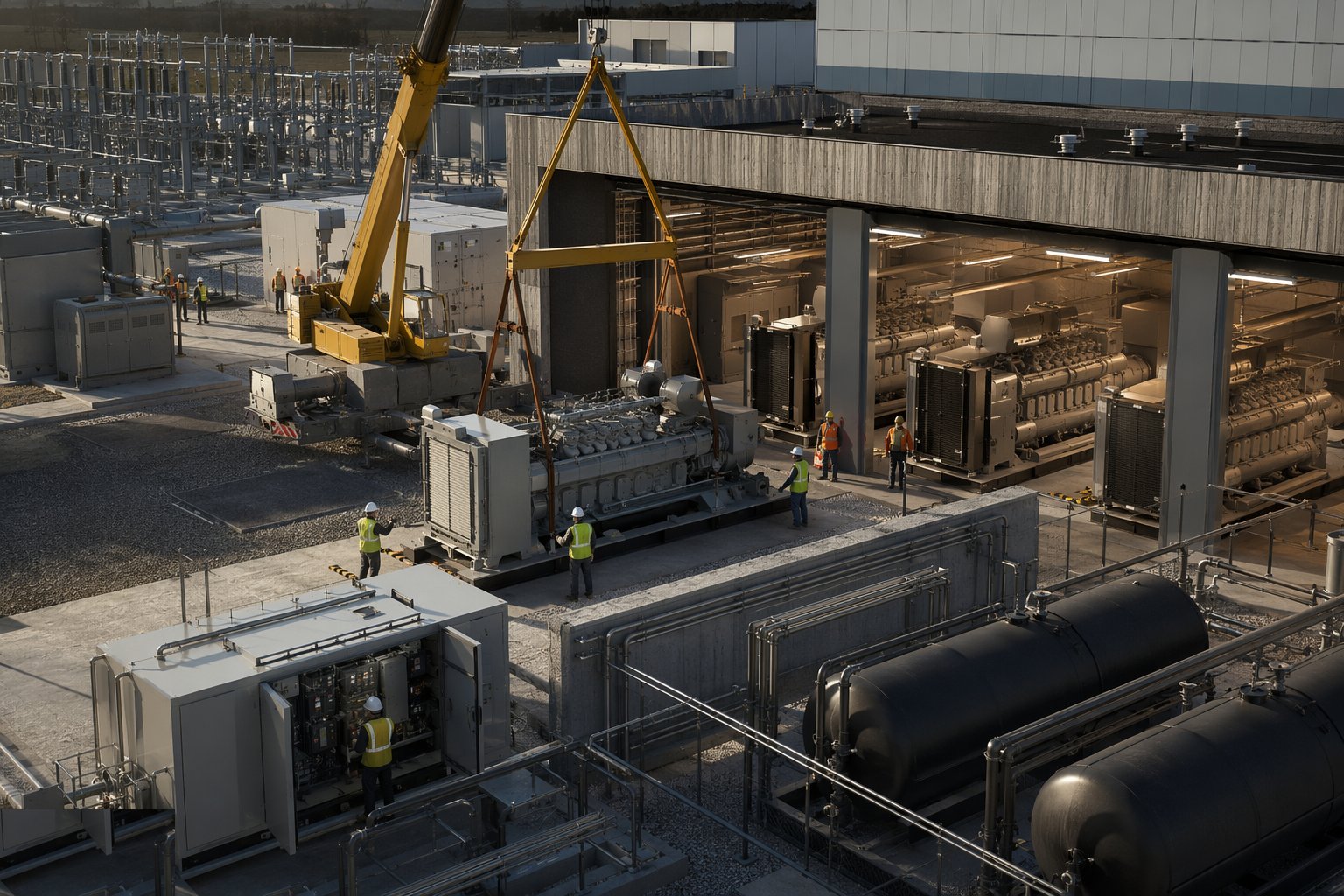
Set the generator sets on inertia bases with vibration isolation, install exhaust and cooling air systems with the attenuation the neighbours and the environmental permit require, and build the fuel chain: bulk storage with bunding, transfer pumps, day tanks, polishing systems and the fill-point logistics that let a tanker resupply under security. Test each set off-load then on-load, prove the synchronising and load-sharing controls across the farm, and run the black-start and step-load sequences the integrated testing will later demand. Fuel is sampled and polished on a regime from the day it is delivered — standby diesel degrades, and a generator that cannot start on day 900 of standby is sculpture.
Step 6: Install busway, distribution and rack-level power
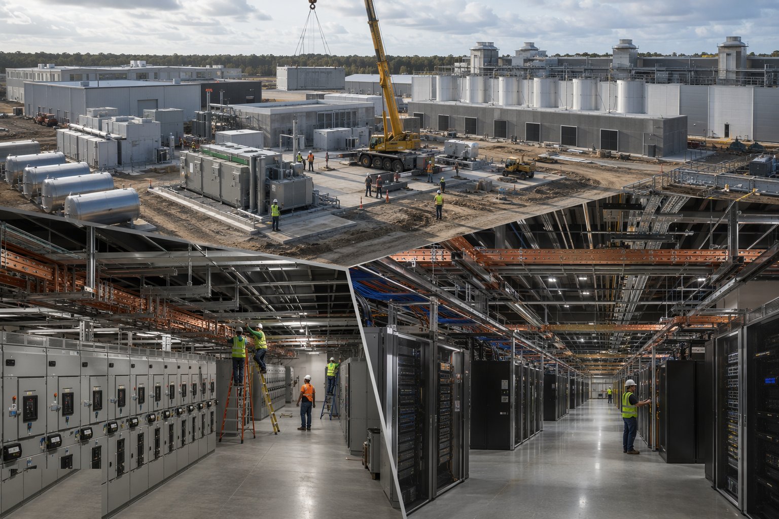
Run the busway along the hall ceilings on engineered supports with expansion provisions, fit tap-off boxes per the rack layout, and install remote power panels, static transfer switches and rack PDUs where the design puts them. Metering and monitoring wiring goes in with the power — every board, tap-off and PDU reporting to the DCIM from day one. Terminations are torqued and thermally surveyed; a loose busbar joint announces itself as a hot spot at 2 MW of load, and the infrared survey at commissioning exists to find it first.
Step 7: Prove the chain with load-bank testing
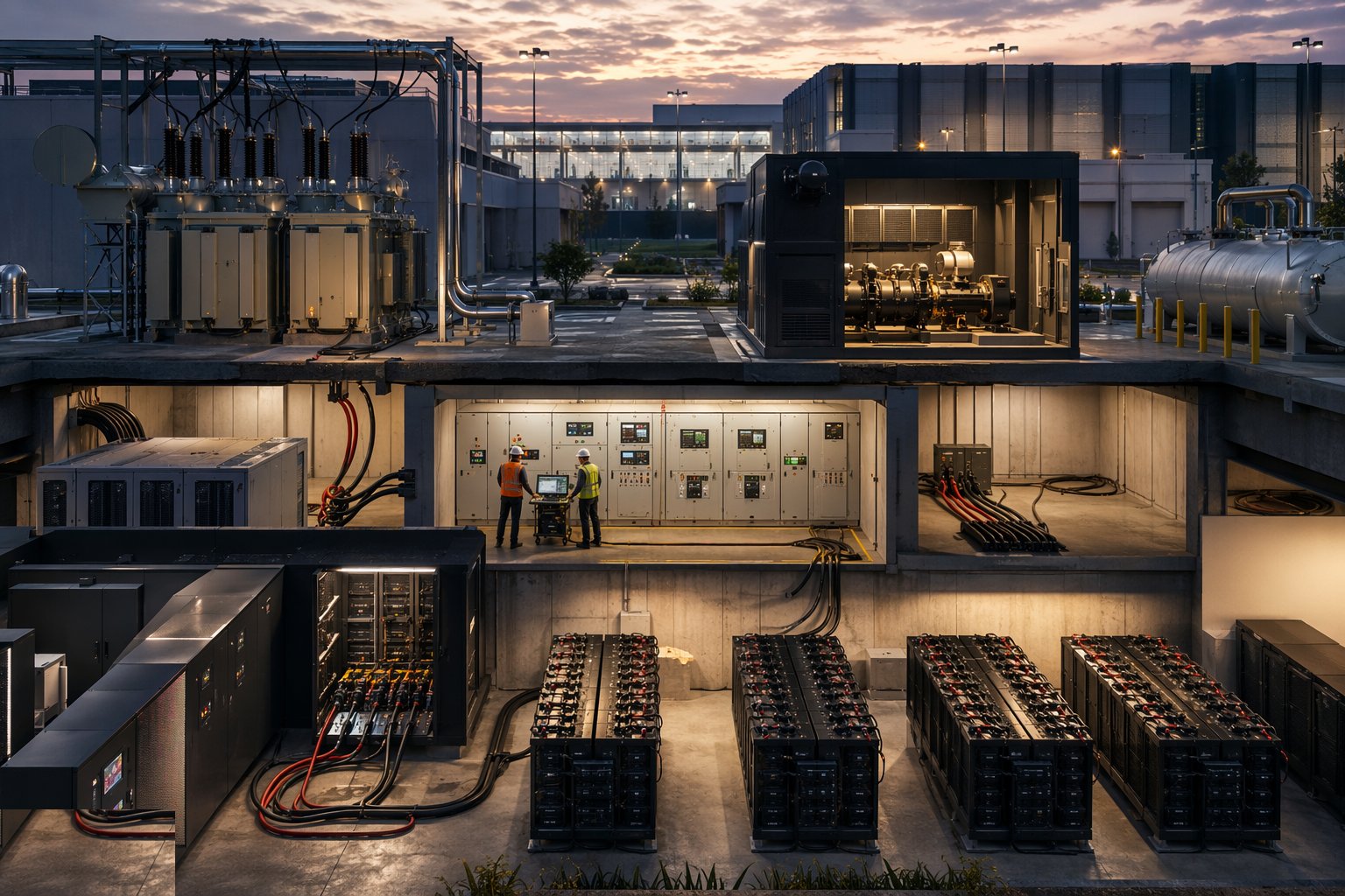
Before IT load arrives, prove the entire chain with load banks: energise through the utility intake, load the UPS systems to full rating, run the generators under sustained load, exercise every transfer and changeover sequence, and thermal-survey the lot under load. Test the failure modes the redundancy philosophy promises — pull a UPS module, kill a generator, open an A-train breaker — and prove the load carries on. Every test is scripted, witnessed and recorded; the results feed the integrated systems testing and, where pursued, the Tier certification that the client will market.
Plant and equipment
- HV switchgear, ring main units and protection test/injection sets
- Transformers (cast resin and oil-filled) with containment and cooling
- Modular and monoblock UPS frames with VRLA or lithium battery systems
- Diesel/HVO generator sets with synchronising and load-sharing controls
- Bulk fuel tanks, day tanks, transfer and polishing systems
- Busbar trunking (busway) with tap-off units and rack PDUs
- Load banks (resistive, and reactive where specified) for chain proving
- Thermal imaging cameras and power quality analysers
Quality control checks
- Factory acceptance tests witnessed for switchgear, UPS and generators before shipment
- Cable termination and torque records with infrared surveys under load
- Protection grading studies injected and signed off by the protection engineer
- Physical separation of redundant trains verified as built — rooms, routes, compartments
- Battery autonomy discharge tests recorded against the specified minutes at full load
- Load-bank test scripts executed, witnessed and filed with every failure mode proven
Safety considerations
- High-voltage work under permit-to-work with authorised persons — no improvisation, ever
- Arc-flash risk: rated PPE, engineered settings, and live working avoided by design
- Battery rooms: hydrogen management for VRLA, thermal runaway provisions for lithium, eye wash and spill kits
- Fuel systems: bunding, hot-works exclusion, and Civil Defence/environmental compliance
- Heavy lifts: transformers, switchboards and generators moved under engineered lift plans
- Noise and exhaust during generator testing — attenuation, monitoring and neighbour management
Common defects
- Protection mis-graded — a local fault tripping a whole board and taking a hall with it
- A/B train separation compromised in the build — shared containment or rooms that make 2N a paper claim
- Loose busway or termination joints — hot spots found (or not found) at full load
- Fuel left unpolished through a long construction period — generators failing their first serious run
- Battery autonomy short of spec because the room overheats — the five minutes that was four
- Metering and DCIM points missed at installation — retrofitting monitoring into live distribution
Best suited for
- Hyperscale, colocation and enterprise facilities from a few MW to campus scale
- Facilities targeting Uptime Tier III/IV certification
- Sites where utility capacity and phasing drive the masterplan
- AI and high-density deployments pushing power density per rack ever upward
How long does Power Infrastructure take?
Typical duration: Utility agreement to energisation typically 18–36 months on new connections; on-site electrical installation 6–12 months per building phase, with load-bank testing adding 4–8 weeks..