Rail Electrification — OLE & Conductor Rail
Foundations, masts and portals, contact and catenary wires run out and tensioned — or conductor rail laid and bonded — the power delivery system of an electric railway.
Last updated 2026-07-28 by the BuildPedia Editorial Team.
What is Rail Electrification — OLE & Conductor Rail?
Electrification is what turns a railway into an electric railway, and it comes in two physical forms. Overhead line equipment — OLE, or catenary in US usage — hangs the live contact wire above the track on masts, portals or headspans, carrying 25 kV AC single-phase on main lines. Conductor rail puts the power at track level: a third rail at 750 V DC on suburban and metro networks, and the four-rail system on older metros such as London Underground, where a centre rail at +420 V and an outside rail at −210 V keep the return current out of the ground. Each system has its own construction grammar, but both are the same job in essence: deliver continuous, well-registered, well-bonded power conductor along every metre of the route, sectionalised so a fault kills a section and not the network.
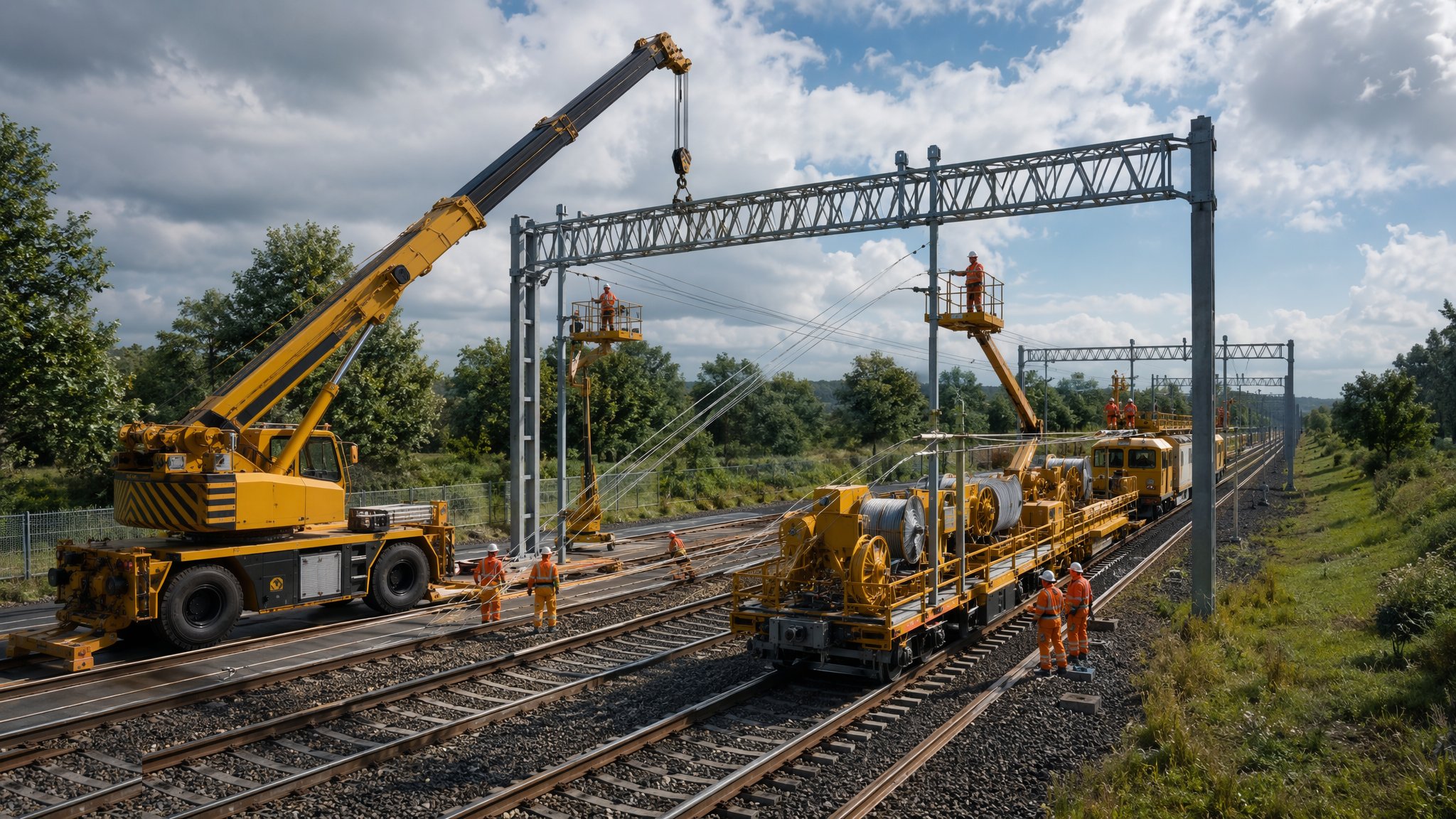
OLE construction is a sequence that tolerates no skipping. Foundations — concrete bored or driven steel piles — are cast to the design loads because a mast carrying wires under tension is a structure, not a fence post. Masts or portal frames are erected, the cantilevers and registration equipment that hold the wire in position are fitted, and the wires themselves — catenary and contact wire in a tensioned pair — are run out from drum trailers and tensioned with auto-tension weights so the contact wire hangs at the right height with the right stagger over the rail. Every junction of electrical sections gets its insulators and neutral sections, every structure gets its bonds, and the whole route is proven by survey and by test train before it is energised.
In the Gulf, electrification means the metros: Dubai Metro runs 750 V DC third rail, as do Doha and Riyadh, and the conductors are steel-aluminium composite rail that halves the weight and resistance of the old steel sections. The urban challenge is the depot and the interface with the public realm — conductor rail covers and boarding at every crossing and walkway, because a live 750 V rail at ankle height does not forgive. Etihad Rail's main line is built ready for future electrification, which means the clearance and structure gauge work of this process is being done now even where the wires are not.
When and why is Rail Electrification — OLE & Conductor Rail used?
Electrification follows track construction because the OLE registers to the rail — wire height and stagger are measured from the running rails — and it must be substantially complete before dynamic testing can begin. It matters because it is simultaneously a structural, electrical and gauging exercise: a mast out of plumb, a wire out of register or a bond left off will be found by a pantograph at speed, and the finding is expensive and public. It also gates the energisation milestone, which gates every test train, which gates trial running — so the wiring gangs sit near the top of every project's critical path, and their documentation, from foundation records to tensioning certificates, is part of the safety case for energisation.
Types of Rail Electrification — OLE & Conductor Rail
25 kV AC overhead line equipment
The main-line standard: auto-tensioned catenary and contact wire on cantilevers carried by masts or portals, sectioned with insulators and neutral sections between feeder stations. High power and long distances between substations, at the cost of a visible structure every 50–70 m and a demanding registration tolerance.
750 V DC third rail
A top-contact conductor rail on insulators beside the running rails, with cover boarding wherever staff or the public can reach it. Simple, robust and proven across suburban and metro networks — but voltage drop limits substation spacing, and the safety regime around a ground-level live rail is absolute.
Metro four-rail system
The deep-tube arrangement: a centre conductor rail at positive potential and an outside rail at negative, so return current never uses the running rails or the ground. It protects old tunnels and buried services from stray-current corrosion, at the price of more rail, more bonds and more protection equipment.
Tramway and depot OLE variants
Simple contact wire without catenary for lower-speed running, section insulators and crossovers for depots and sidings, and rigid overhead conductor rail in tunnels where clearances forbid conventional equipment. Same physics, tighter envelopes, and usually the first sections energised for testing.
Rail Electrification — OLE & Conductor Rail: step by step
Step 1: Install the OLE foundations
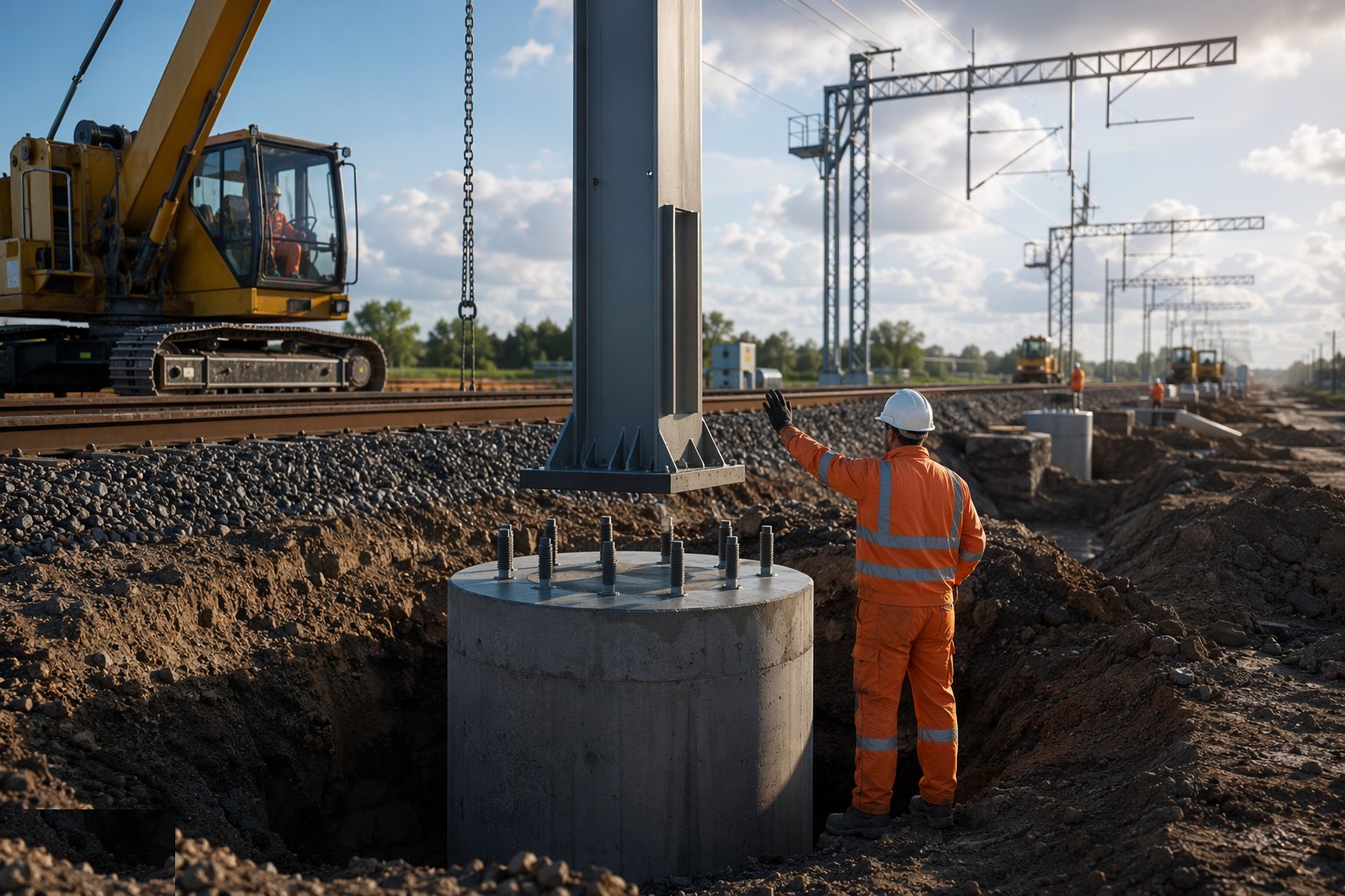
Set out and construct the mast and portal foundations from the track survey: bored concrete or driven steel foundations cast or driven to the design loads, with anchor bolt assemblies set to template and surveyed before the concrete takes its set. Foundation records — position, level, torque or test results — are kept per structure, because a foundation that is out will move the wire out of register fifty metres in the air, and the fix is a new foundation, not a shim.
Step 2: Erect masts, portals and cantilevers
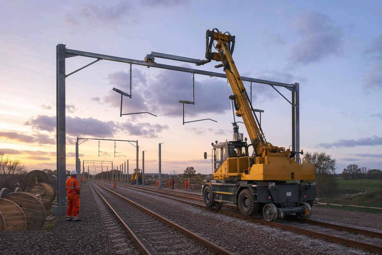
Stand the masts or erect the portal frames with road-rail plant, plumb them and torque the holding-down bolts, then fit the registration equipment — cantilevers, registration arms, steady arms — built up from the design sheets for each structure. Every structure carries a plate with its number and design data; the as-built survey of the finished steel is the baseline the wire installation works from, and it is checked before a single drum is loaded.
Step 3: Run out and clip up the wires
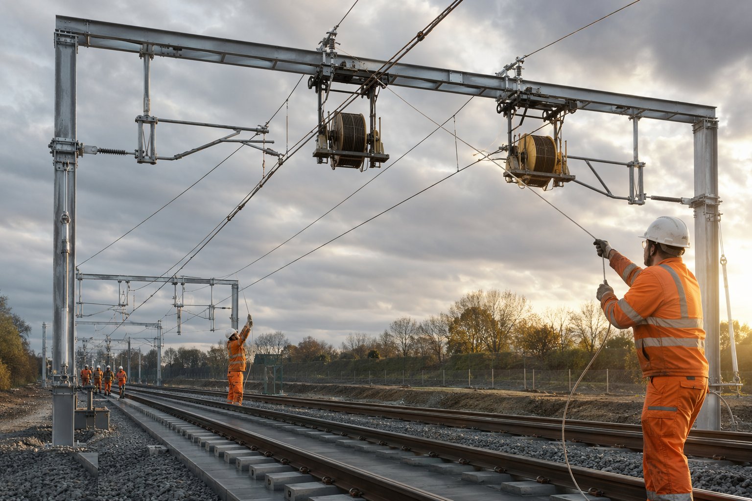
Run the catenary and contact wires out from drum carriers under controlled braking so they never bird-cage or kink, clip them up into the registration equipment, and terminate them into the auto-tension equipment with the balance weights set for the section length. Wire damage during running is a cut-out and re-run — a kinked contact wire will destroy a pantograph — and every wire run is logged by drum number and chainage for traceability.
Step 4: Register, tension and survey the contact wire
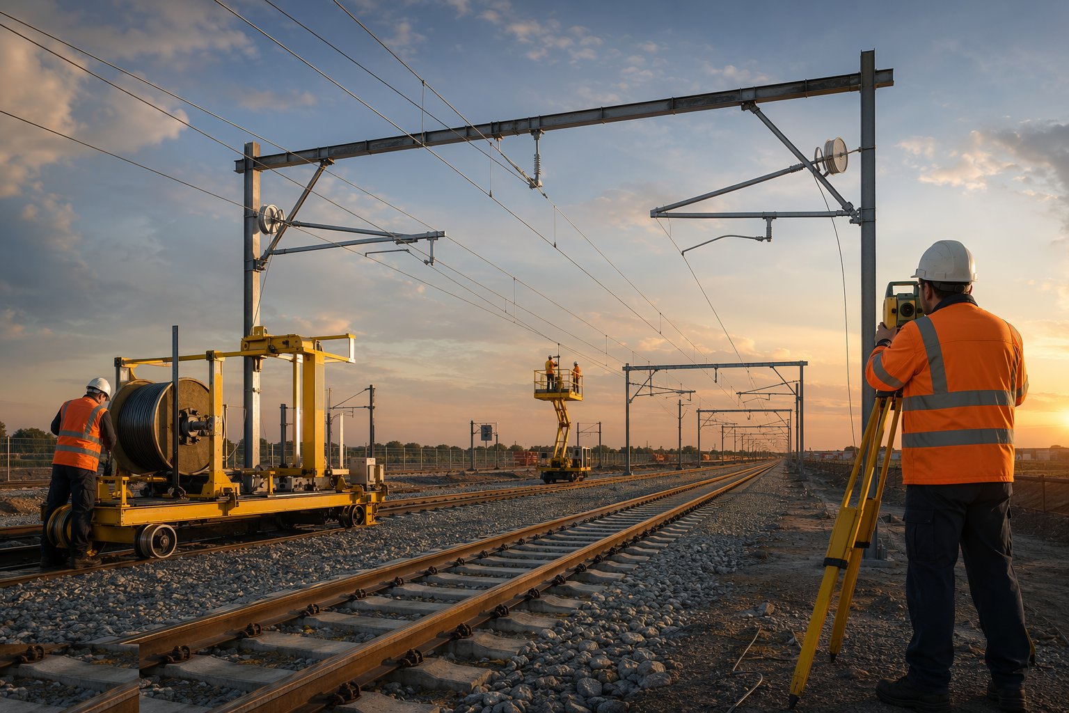
Set the contact wire to its design height and stagger at every structure and mid-span, working through the section with measuring gauges from the running rails. Check wire height, stagger, gradient and the clearances at overbridges and turnouts against the gauging requirements, and record the lot. This is the step the pantograph will grade at line speed; the tolerance is tens of millimetres and the checking is done twice.
Step 5: Install sectioning, bonds and the return path
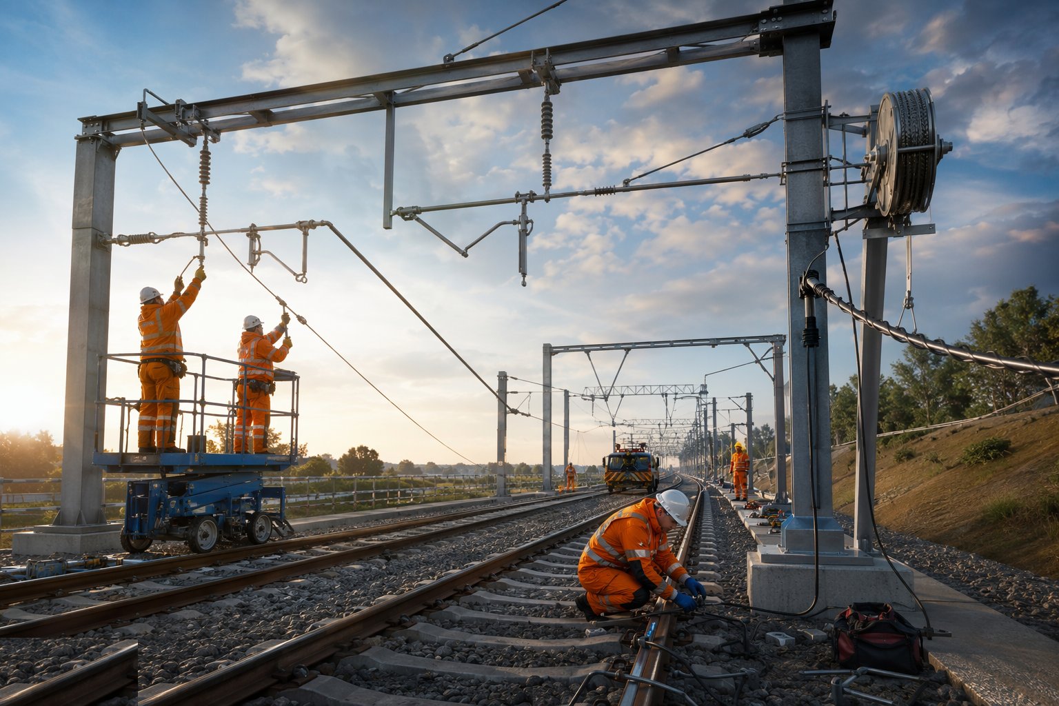
Fit the section insulators, neutral sections and switches that divide the route into electrically separable sections, then complete the bonding: structure bonds, rail bonds, impedance bonds at track circuit boundaries and the return conductors that carry current back to the feeder stations. A missing bond is a voltage on a piece of steel that should be dead — the bond schedule is a checklist with signatures, not a memory exercise.
Step 6: Test, commission and energise

Prove the system dead before it goes live: continuity and insulation resistance tests on every section, protection settings proven at the feeder stations, and the electrical clearances surveyed. Then energise in sections under a permit regime, run the pantograph test train at creeping speed checking for snatching and dewirement before any speed is built up, and only then hand the electrified railway over to the testing programme — with the electrical safety rules in force for every person who goes near it from that day forward.
Plant and equipment
- Road-rail cranes and MEWPs for mast erection and wiring access
- Wiring trains and drum carriers with tension control
- Piling rigs and foundation excavators for OLE foundations
- Torque equipment and foundation test sets
- Wire measuring gauges, laser height-and-stagger instruments
- Conductor rail laying and jointing equipment for third-rail systems
- Sectioning and bonding test equipment — continuity and insulation testers
- Pantograph test vehicles for dewirement and interaction testing
Quality control checks
- Foundation positions and levels surveyed per structure before steel erection
- Wire height and stagger recorded at every structure and mid-span
- Auto-tension equipment set and certified per section, with weights locked
- Bond schedule completed and signed off — structure, rail and impedance bonds
- Continuity and insulation resistance test records per electrical section
- Gauging and electrical clearance survey completed before energisation
Safety considerations
- The whole works becomes an electrical hazard at energisation — permits, isolation and earthing discipline
- Working at height on masts and portals: harnesses, MEWP controls and dropped-object prevention
- Wire run-out under tension: exclusion zones in the line of drums and pulling ropes
- Third-rail working: cover boarding and treating every rail as live until proven earthed
- Road-rail plant operations near live track: possession and lookout discipline
- Lifting operations over or beside the track under controlled lift plans
Common defects
- Foundations out of position — wire registration that can never be made right
- Wire kinked or damaged during run-out and clipped up anyway — a pantograph strike waiting for speed
- Balance weights set or locked wrong — contact wire height wandering with the seasons
- Bonds missed on remote structures — stray voltage found by a maintainer, not a tester
- Stagger set by eye instead of gauge — contact wire wear concentrated on the pantograph horns
- Cover boarding incomplete on conductor rail — an open invitation at ankle height
Best suited for
- Delivering continuous, sectionalised power along every metre of the route
- 25 kV AC main lines and 750 V DC metro and suburban networks
- The energisation milestone that unlocks the entire dynamic testing programme
- Gauging-critical works where the wire must register to the rail within tens of millimetres
How long does Rail Electrification — OLE & Conductor Rail take?
Typical duration: OLE construction typically progresses 1–2 km of wiring per week per wiring train after foundations and steel are complete; the foundations and steel programme usually runs months ahead on the critical path..