Shafts & Portals
The deep excavations that let tunnelling begin — launch and reception shafts, and the portal structures where the tunnel meets daylight.
Last updated 2026-07-28 by the BuildPedia Editorial Team.
What is Shafts & Portals?
Every bored tunnel starts and ends in a hole dug from the surface. The launch shaft is where the TBM is lowered in pieces and assembled; the reception shaft is where it emerges and is recovered; and between projects, shafts double as ventilation shafts, intervention and emergency access points, pumping stations and permanent maintenance access. A shaft is therefore never just a construction expedient — its lining, its base and its headworks usually become part of the finished asset, which is why they are built with the same permanence as the tunnel itself. Portals are the surface end of the story: the tunnel mouth structures, portal walls and cut-and-cover boxes that carry the alignment from underground to daylight, with their retaining walls, drainage and — for road and rail — the approaches and safety transitions.
Shaft construction methods follow the ground and the depth. Secant piled shafts — interlocking bored piles forming a circular wall — and diaphragm wall shafts handle most urban work, propped internally by ring beams or slabs as excavation descends. For the deepest shafts, a segmental caisson is built at the surface and sunk under its own weight, rings added at the top as it goes. Where the water table is high — and on Gulf coastal sites it is always high — the base is sealed against uplift with a tremie concrete plug or ground treatment, and dewatering runs from before excavation until the structure is heavy enough to resist flotation.
The UAE has limited but telling experience: the Dubai Metro stations and crossover structures were built as deep diaphragm-walled boxes in water-bearing sands and weak rock, and the deep storm-water programme — the Dubai Municipality Deep Tunnel Storm Water System and the wider Tasreef programme — includes shafts of exceptional depth, with the terminal pumping station structure extending to around 60 m. Ground conditions mean groundwater control dominates every design decision: dewatering discharge needs its own approvals, saline water attacks concrete and dewatering kit alike, and the design life expectation for these structures is 100 years.
When and why is Shafts & Portals used?
Shafts and portals come first in any tunnelling sequence because nothing else can start without them: the TBM launch, muck removal, segment delivery, ventilation and power all run through the shaft, and the programme of the entire drive is set by when the shaft is ready. They are also the highest-consequence excavations on the project — deep, often beside live roads and buildings, below the water table — so their design, monitoring and temporary works control set the safety tone for everything that follows. The small-scale echo is real but modest: a deep pumping chamber or a sheeted cofferdam to rebuild a riverside bank wall is a shaft in miniature — perimeter support, staged dig, groundwater control and a sealed base — built by a piling rig and a 360 where this page uses diaphragm-wall plant.
Types of Shafts & Portals
Secant and contiguous piled shafts
A circular wall of bored piles — interlocking (secant) where water must be cut off, touching (contiguous) where it need not — excavated down in stages with ring beams or internal propping. Flexible in size and depth, quiet enough for urban sites, and the piles are proven technology; the trade-off is the propping jungle the TBM assembly must work around.
Diaphragm wall shafts and boxes
Panels of reinforced concrete wall built in trenches held open with bentonite slurry, forming the shaft perimeter before excavation starts. The walls become the permanent structure — the method behind deep metro boxes and pumping stations — and they control groundwater well, at the cost of specialist plant, slurry handling and serious temporary works design.
Segmental caisson shafts
A shaft built at the surface from precast rings and sunk under its own weight as the ground is excavated from inside, rings added at the top as it descends. Self-supporting throughout and excellent for very deep shafts in soft ground, but sinking must be controlled — plumb, level and at a steady rate — because a caisson that sticks or tilts is a major recovery operation.
Portal structures
The tunnel mouths: cut-and-cover boxes, portal headwalls and approach ramps with their retaining walls, drainage and — for metros and roads — the transition structures where the tunnel meets the open alignment. Usually the last tunnelling structure to finish and the first the public ever sees, with architecture and landscape treatment to match.
Shafts & Portals: step by step
Step 1: Set out, clear and monitor the shaft site
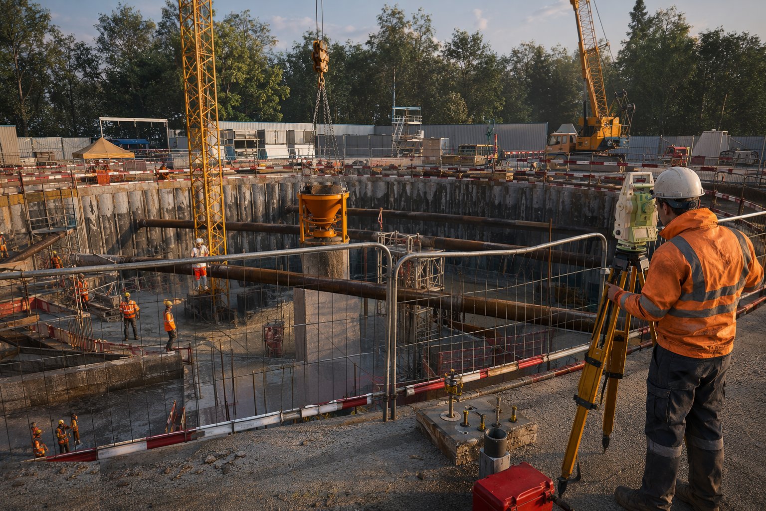
Set out the shaft from corridor control, clear services by scan and trial hole, and establish the baseline monitoring: survey points on surrounding structures and surfaces, inclinometer and piezometer installations around the shaft, and trigger levels agreed with the designer. Deep excavations move the ground around them; the monitoring is installed before the first pile goes in, because the baseline is only valid before the ground is disturbed.
Step 2: Construct the perimeter wall
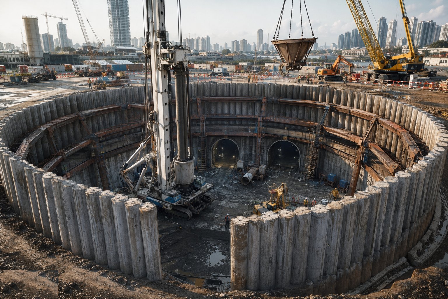
Build the shaft wall to its full depth before bulk excavation: bore the secant piles in their hit-and-miss sequence, or excavate the diaphragm wall panels under slurry and tremie the concrete, or assemble and pitch the first caisson rings on their cutting edge. Every element is logged — depths, slurry properties, concrete volumes — and tested: integrity tests on piles, panel verticality, joint quality between elements, because the wall is both the earth support and the permanent lining.
Step 3: Excavate in stages with propping
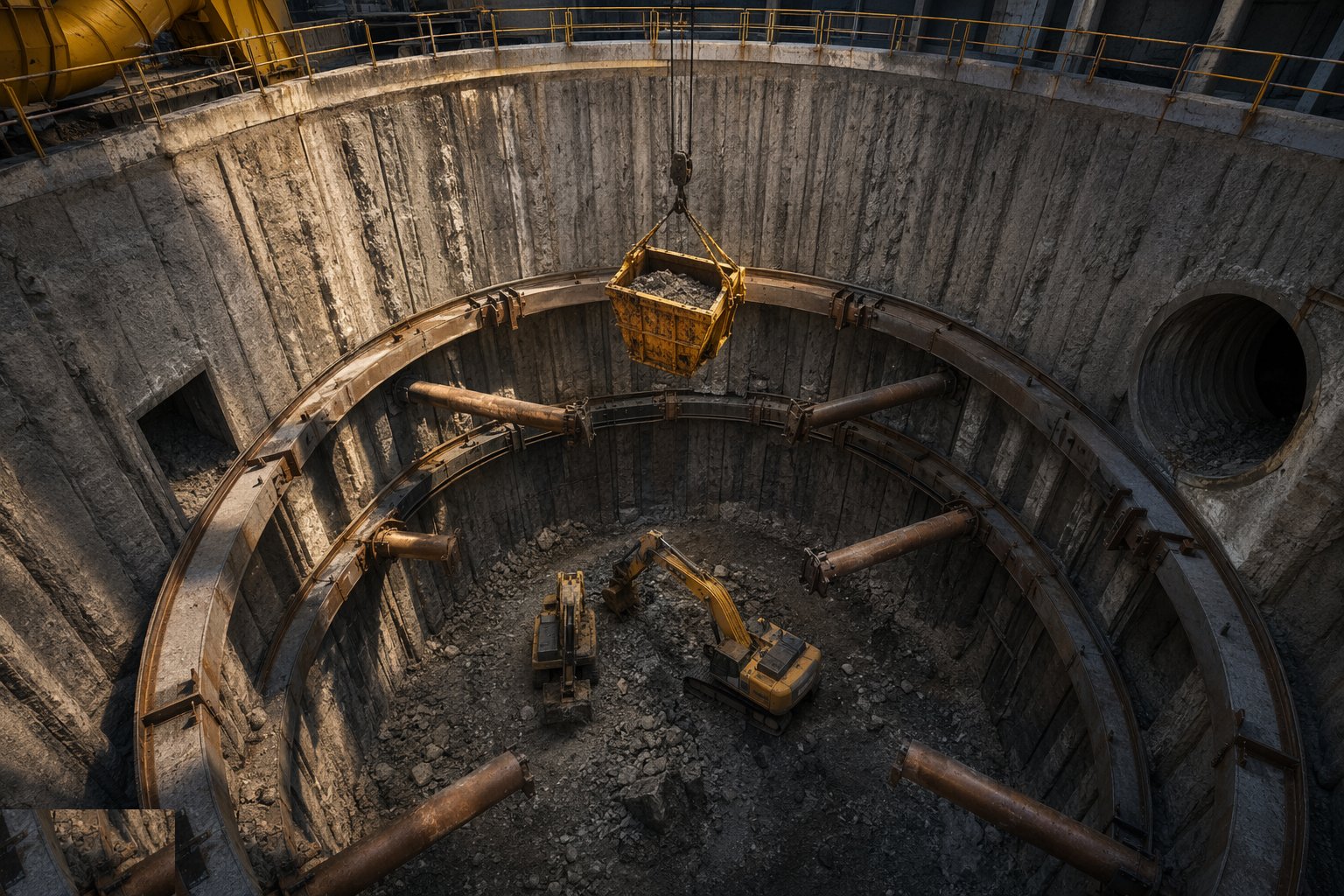
Excavate inside the wall in planned stages, installing ring beams, walers, struts or permanent slabs at each level before digging deeper — the rule is never below the support. Material comes out by crane-skip or clamshell; the excavated face of the wall is inspected as it is exposed for leaks, defects and ground behaviour, and the monitoring is read daily. A wet joint or a bulging panel is a stop-and-think event, not a keep-digging event.
Step 4: Control groundwater and seal the base
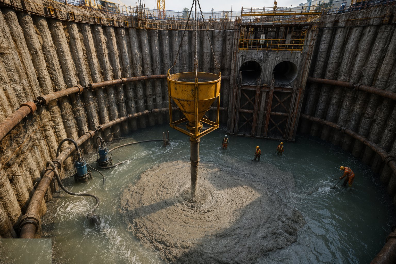
Keep the shaft dry and stable at depth: dewatering wells or eductors around the perimeter where the ground allows, pumped sums where it does not, with discharge only to consented outlets — in Dubai the discharge approval is in hand before pumping starts. At formation, seal against uplift: a tremie concrete base plug placed under water where inflow cannot be excluded, or ground treatment beneath the base. The plug is designed against flotation for the empty-shaft condition — an empty shaft in wet ground is a boat.
Step 5: Cast the base slab and form the TBM eye
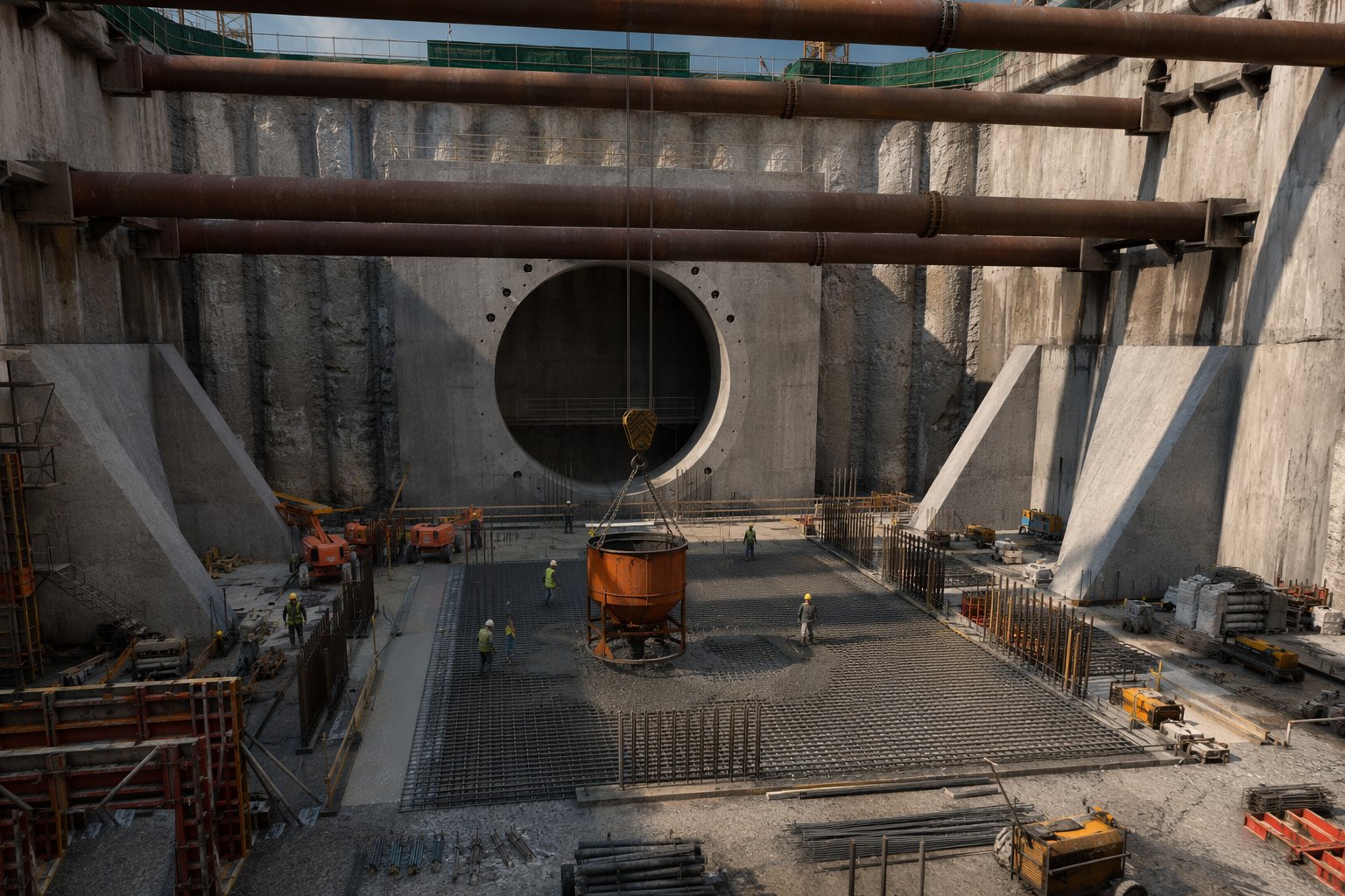
With the base sealed and dry, cast the structural base slab — heavily reinforced, anchored against uplift — and build the internal walls, benches and plinths the shaft needs: TBM cradle and launch frame foundations in a launch shaft, sumps and pump plinths in a pumping shaft. Form the tunnel eye — the opening in the shaft wall where the TBM launches or is received — with its seal arrangement; breaking the eye is deliberately left until the machine is ready, and the ground beyond it is treated or frozen if it cannot stand open.
Step 6: Build the headworks and portal structures
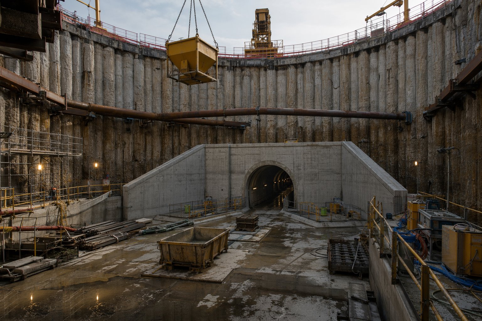
At the surface, cast the collar and headworks: the capping structure that takes the crane rails, the ventilation connections, the permanent access and the final covers. At portals, construct the headwall and wing walls, the approach retaining structures and the portal drainage that stops surface water ever entering the tunnel — the portal is the tunnel's umbrella. Portal zones are also where the public realm lands: finishes, barriers and lighting transitions are built here to the road or rail authority's detail.
Step 7: Fit out the shaft for tunnelling operations
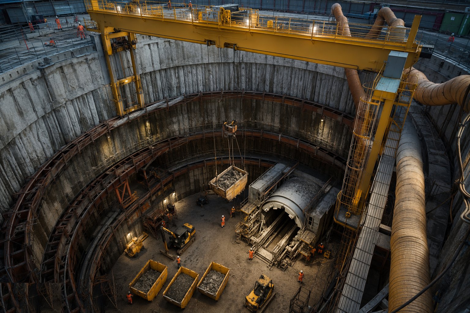
Turn the finished shaft into a working tunnelling hub: gantry crane or craneage for segments and muck skips, muck-handling arrangements at the surface, ventilation ducting down to the drive, power and communications distribution, access ladders or hoists, and the emergency arrangements — rescue access, refuge provision, fire fighting — required before the drive starts. Only then is the shaft handed over to the tunnelling crew, with its own inspection and maintenance regime for the life of the drive.
Plant and equipment
- Bored piling rigs and hydromills or grabs for diaphragm walls
- Bentonite slurry plant: mixing, recycling and desanding
- Cranes for muck skips, cages, panels and TBM components
- Dewatering well systems, eductors and submersible pumps
- Tremie pipes and underwater concrete equipment for base plugs
- Propping: ring beams, walers, struts and hydraulic frames
- Shaft gantry cranes, hoists and muck-handling skips
- Monitoring instruments: inclinometers, piezometers, prisms and load cells
Quality control checks
- Wall element records: pile logs or panel records, slurry test results, concrete volumes per element
- Integrity testing of piles and joints; verticality surveys of wall elements
- Monitoring read against trigger levels daily — movement, water level, strut loads
- Base plug and base slab concrete records; uplift design verified against actual water levels
- Dewatering discharge consents current; water quality monitored where required
- Tunnel eye and seal installation surveyed and pressure-tested where specified
- Durability class of all below-water concrete verified — saline ground demands the records
Safety considerations
- Deep excavation control: never excavate below installed support; edge protection and controlled access at every stage
- Confined space procedures as the shaft deepens — gas testing, ventilation, rescue arrangements
- Crane-skip mucking over an open shaft: exclusion below the skip line, banksman control
- Groundwater and inflow risk: dewatering maintained, emergency pumping and evacuation plan rehearsed
- Lifting TBM components and heavy plant into the shaft under planned, supervised lifts
- Noise, dust and traffic management for urban shaft sites beside live roads
- Heat and humidity management in deep shafts on Gulf sites — ventilation from early in the excavation
Common defects
- Leaking joints between wall panels or piles — water and fines washing in, subsidence outside the shaft
- Base plug too thin or debonded: uplift cracking and an unplanned swimming pool
- Struts installed late or under-torqued: wall movement shows on the inclinometers a week later
- Monitoring ignored — the readings passed trigger level three shifts before anyone looked
- Caisson sunk out of plumb: the tunnel eye no longer faces the tunnel
- Dewatering discharged without consent or onto a neighbour — stop-work and a claim
- TBM eye broken before the ground beyond was treated: the face runs and the shaft fills with sand
Best suited for
- Launch and reception points for TBM and pipejack drives
- Deep excavations needing designed temporary and permanent support
- Portal structures where the tunnel meets the surface road or railway
- Ventilation, intervention and emergency access shafts on long drives
How long does Shafts & Portals take?
Typical duration: 4–9 months for a typical launch or reception shaft including fit-out; exceptionally deep pumping and terminal shafts run 18 months and more; portal structures typically 3–6 months..