TBM Tunnelling & Segmental Lining
Mechanised tunnelling: the machine, the muck, and the gasketed precast rings that become the finished tunnel.
Last updated 2026-07-28 by the BuildPedia Editorial Team.
What is TBM Tunnelling & Segmental Lining?
A tunnel boring machine is a factory on wheels: it excavates the face, supports the ground, erects the permanent lining and removes the spoil, all in one continuous cycle, ring by ring. The lining it builds is usually the finished structure — precast concrete segments bolted into rings inside the machine's tail shield, sealed at every joint with compression gaskets, and locked into the ground by grout injected into the annular gap the machine leaves behind. When a TBM drive is going well, a finished tunnel appears behind it at a steady walking pace, day and night, for months.
Machine selection is a ground decision, not a preference. Earth pressure balance (EPB) machines condition the excavated soil into a paste and balance face pressure with a screw conveyor — the right choice in cohesive and conditionable soils. Slurry (mixshield) machines support the face with pressurised bentonite slurry and pump the spoil out in pipes — the right choice in highly permeable ground, coarse sands and gravels, and high water pressures. The wrong machine for the ground means face instability, settlement above, and a very bad year. Ground control is exercised through face pressure, grout volumes and steering, all watched against a dense web of settlement monitoring at the surface.
The Gulf's tunnelling record is written in exactly these machines: the Dubai Metro's bored tunnels were driven by EPB machines through weak rock and water-bearing sands, and Abu Dhabi's deep sewerage tunnel programme — over 40 km of deep interceptor — used EPB machines as well. Dubai Municipality's Deep Tunnel Storm Water System adds a 10 km, 10 m diameter storm and groundwater tunnel at around 40 m depth, engineered for a 100-year life in saline ground, with the wider Tasreef programme extending deep-tunnel drainage across the emirate. High saline groundwater, abrasive sands and weak carbonate rock define the tunnelling environment: gasketed segmental linings, durable concrete and serious corrosion protection are not options, they are the specification.
When and why is TBM Tunnelling & Segmental Lining used?
TBM tunnelling starts when the launch shaft is ready and runs until breakthrough, because the machine is only economic when it never stops: every stoppage costs a day of the most expensive plant on the project. It is chosen for long, repetitive drives in urban or difficult ground where surface disruption must be near zero — under roads, railways, buildings and utilities — and it matters because it hands over a structurally complete, watertight tunnel that the fit-out trades can follow immediately behind. There is no domestic version of TBM tunnelling; the small end of mechanised tunnelling is pipe jacking and microtunnelling, covered as its own type here, and below that the closest a small site gets is a thrust-bored crossing under a road or railway for a service connection — hired in as a specialist subcontract, not a method you improvise.
Types of TBM Tunnelling & Segmental Lining
Earth pressure balance (EPB) machines
The cutterhead churns the face into a conditioned paste held under pressure; the screw conveyor meters spoil out at the rate that holds that pressure against the ground and groundwater. Foam, polymer and water condition the soil so it behaves — the operator is part tunneller, part soil chemist. The proven choice in clays, silts and conditionable sands, and the type that drove the Dubai Metro and Abu Dhabi's deep sewers.
Slurry (mixshield) machines
The face is supported by pressurised bentonite slurry; spoil is pumped out in pipes to a separation plant at the surface that cleans and recirculates the slurry. The machine of choice in highly permeable sands and gravels and under high water pressure, where an EPB paste cannot hold the face. The surface separation plant is a factory of its own, and slurry disposal and treatment are a logistics chain in themselves.
Hard rock and open-mode machines
Gripper and shielded rock TBMs that bore open-faced through self-supporting rock, gripping the tunnel walls to thrust, with support installed as they pass. Fast in competent rock — no face pressure to manage — but they need the rock to stand, and fault zones and water inflows must be probed and pre-treated ahead of the face.
Pipe jacking and microtunnelling
The small end of mechanised tunnelling: guided micro-TBMs that install pipelines directly behind them, pushed from a drive shaft. The standard method for sewers and utility crossings under live roads and railways where open cut is impossible — a frequent companion to the big drives on the same scheme.
TBM Tunnelling & Segmental Lining: step by step
Step 1: Prove the ground and select the machine
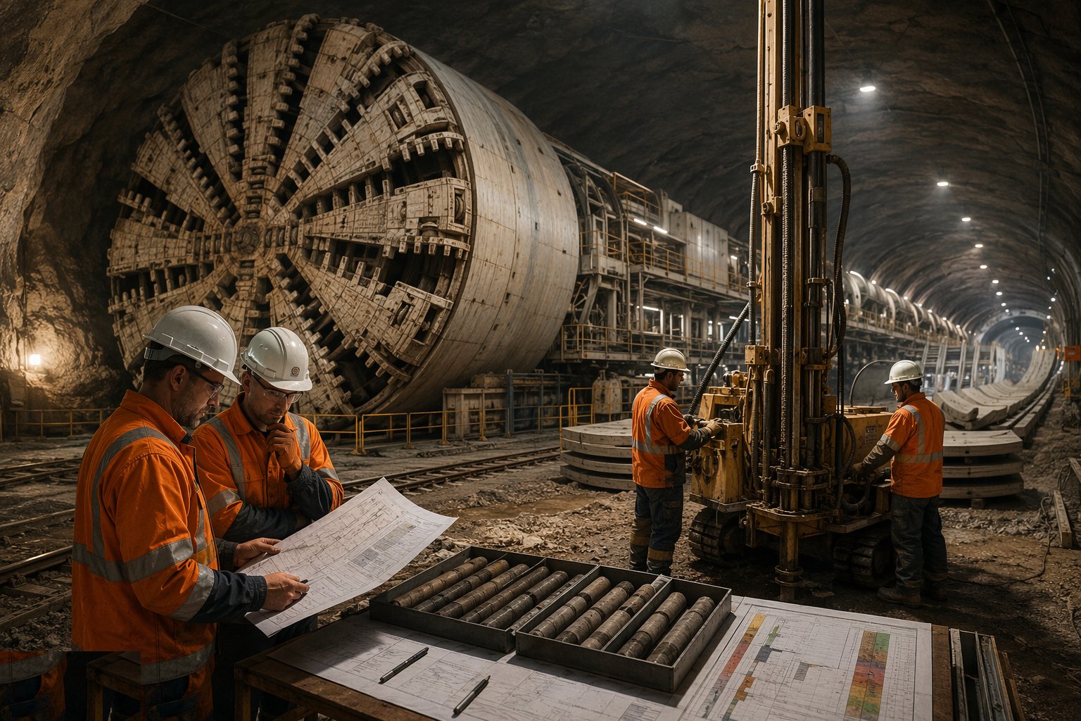
The ground investigation drives everything: grading, fines content, permeability, abrasivity, water pressure along the drive. From it comes the machine type, the cutterhead design and tool selection, the face pressure calculations and the conditioning strategy — and in mixed Gulf ground, the contingency for running sand meeting weak rock at the same face. Instrument the route: settlement points, building monitoring, piezometers, with trigger levels agreed before the machine arrives.
Step 2: Assemble, commission and launch
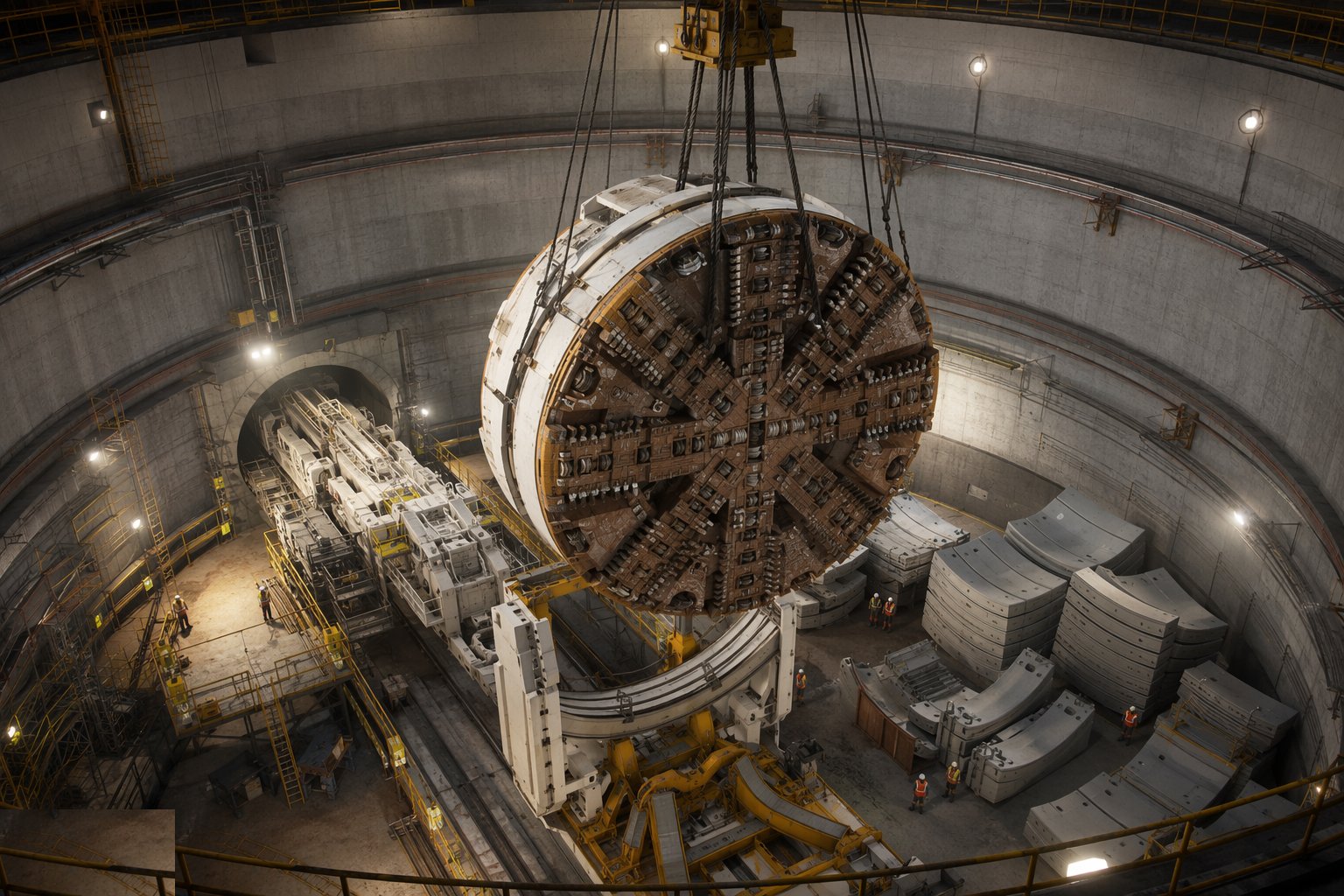
Lower the machine into the launch shaft in pieces — cutterhead, shields, back-up gantries — and assemble on the cradle. Commission every system before the launch: thrust, erector, grouting, mucking, guidance, ventilation, safety systems. Break the tunnel eye through its seal, and drive the first rings inside the shaft and through the eye with the face pressure strategy for shallow cover: the launch is statistically the riskiest part of the drive, because the ground is shallow, the crew is still learning the machine, and everything is new.
Step 3: Drive and build the rings
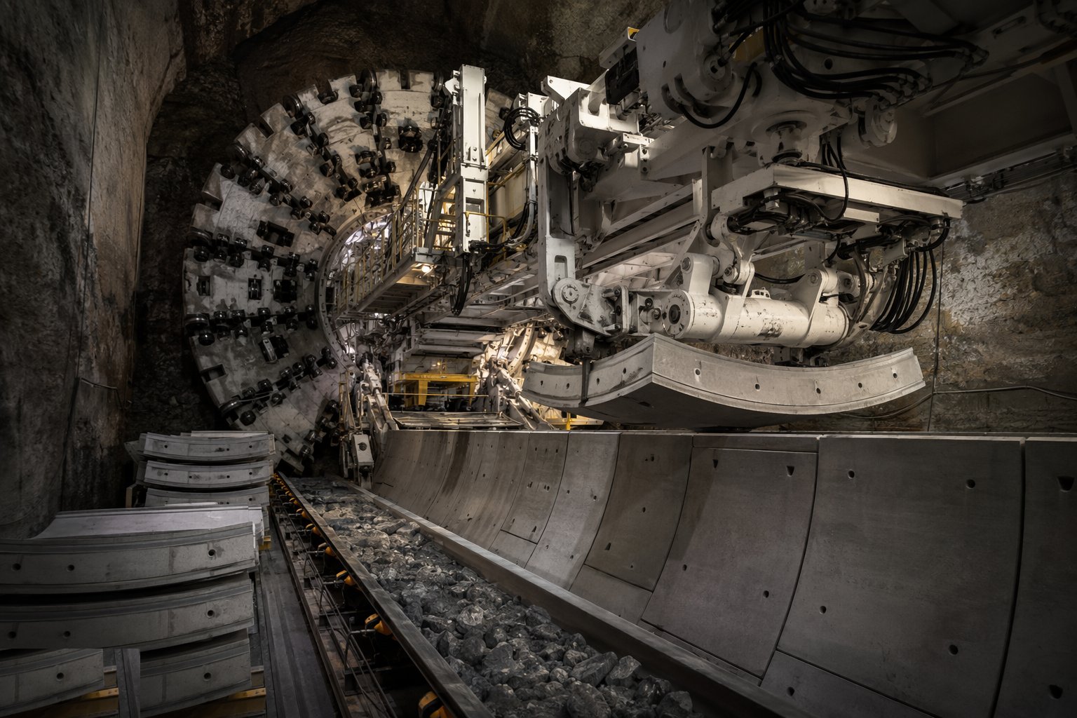
The production cycle: the cutterhead excavates while thrust rams push off the last completed ring; the screw conveyor or slurry circuit holds face pressure within its band; the machine stops at ring length and the erector places each segment with a vacuum pick-up, bolted to its neighbours into a complete ring. Segment delivery, muck removal and grouting must all keep pace — the machine only earns while it is turning. Ring selection (tapered segments) steers the tunnel to line and level, checked continuously by the guidance system against survey.
Step 4: Grout the annulus as you go
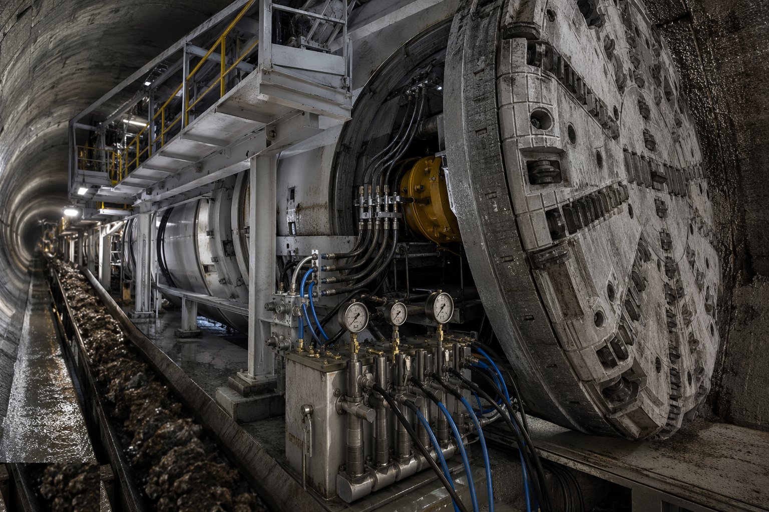
As each ring leaves the tail shield it leaves an annular gap that must be filled immediately: two-component grout injected through the tail at controlled volumes and pressures, filling the void and bedding the ring before the ground can relax into it. Under-grouting means settlement at the surface; over-grouting means heave and distorted rings. Grout volumes and pressures are logged every ring and reconciled against the theoretical volume — the gap between the two is the truth about what the ground is doing.
Step 5: Run the muck and materials logistics
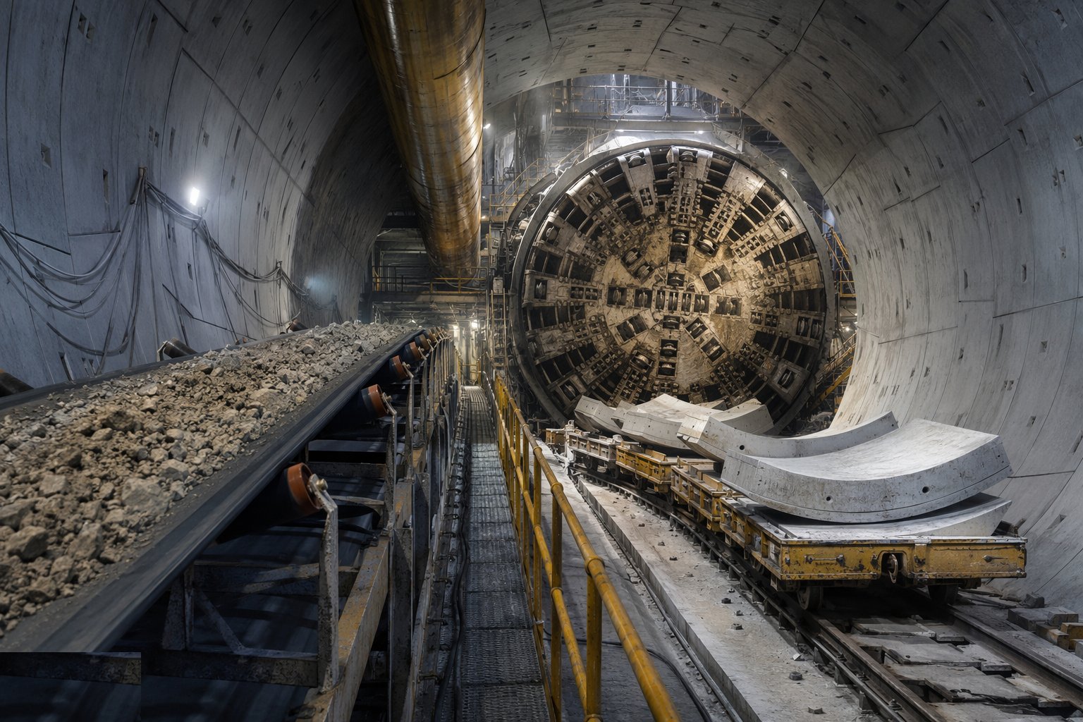
The drive is a supply line: segments, grout materials, grease and consumables go forward; thousands of tonnes of spoil come back — by conveyor and skip to the shaft, or by slurry pipe to the separation plant. Spoil is classified and removed under duty-of-care or the local waste approvals; in the Emirates, conditioned and slurry spoil needs approved disposal routes agreed in advance. A machine stopped for want of skips or a full muck pit is burning money by the hour, so the surface logistics are resourced like a quarry.
Step 6: Monitor the ground and the assets above
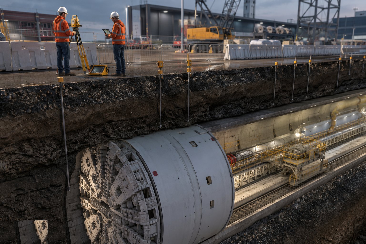
Read the monitoring every shift: surface settlement along the drive, building and utility movements, groundwater levels. Compare against trigger levels — green, amber, red — with actions defined for each: adjust face pressure, increase grout volumes, slow the advance, or stop and investigate. Compensation grouting may be designed in for sensitive structures. The monitoring reports go to the designer and the asset owners above; trust in the numbers is what lets an urban drive proceed.
Step 7: Receive, break through and hand over
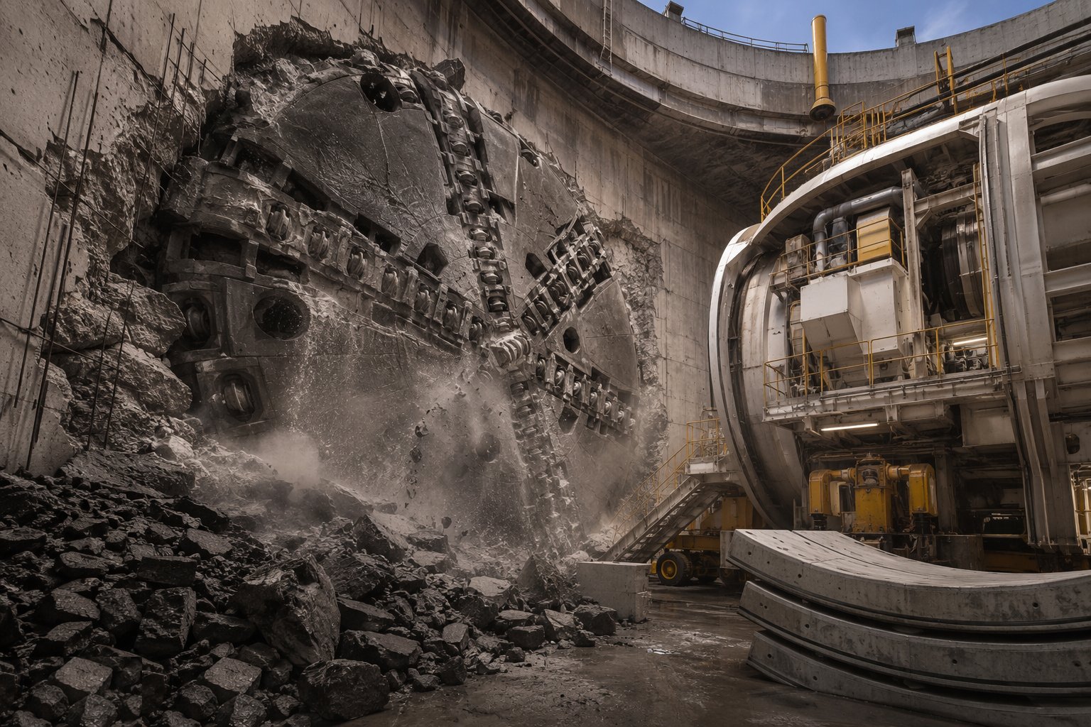
As the machine approaches the reception shaft, treat or verify the ground at the arrival eye, survey the machine's position obsessively in the last rings, and break through into the shaft through the reception seal. Recover the machine, remove the launch and reception seals, and make good the eyes. Then survey and inspect the finished bore: ring build records, grout records, convergence and lining condition, gasket and joint condition, water ingress against the specified tightness — the lining is handed to fit-out as a certified structure, defects logged and made good first.
Plant and equipment
- The TBM itself with back-up gantries: cutterhead, shields, erector, thrust system
- Segment handling: vacuum erectors, feeders, segment transport cars
- Grout plant: batching, pumps and tail-shield injection lines
- Muck systems: conveyors and skips, or slurry pumps and a surface separation plant
- Guidance systems: laser or gyro navigation with survey total stations
- Foam and polymer conditioning systems for EPB drives
- Ventilation, power distribution and communications along the drive
- Monitoring instrumentation: settlement points, prisms, piezometers, data loggers
Quality control checks
- Segment production records: casting, curing, dimensional checks and gasket installation per segment
- Ring build records per ring: build position, bolt torques, ring selection, defects logged
- Grout volume and pressure logged per ring against theoretical annulus volume
- Face pressure records reconciled with advance rate and surface monitoring
- Survey of the built tunnel: as-built alignment and convergence checks
- Water tightness of the completed lining measured against the specified limit
- Durability certification of segment concrete for saline exposure — 100-year designs demand the file
Safety considerations
- Confined space throughout the drive: ventilation, gas monitoring, refuge and evacuation provisions per BS 6164 practice
- Hyperbaric interventions for cutterhead maintenance: specialist procedures, medical lock, strictly controlled
- High-pressure hydraulics, grout and slurry lines: hose management and exclusion during injection
- Transport in the tunnel: segment trains and personnel riders segregated, interlocked and signalled
- Fire risk underground: detection, suppression, escape routes and emergency ventilation from day one
- Heavy lifting of machine components and segments at the shafts under planned lifts
- Heat stress on Gulf drives: ventilation and cooling capacity sized for the environment, not just the machines
Common defects
- Settlement above the drive traced to under-grouted rings — the grout log versus theory gap ignored
- Gaskets displaced or damaged at build: leaking joints that weep forever
- Ring steps and lips from poor build control — waterproofing compromised and clearance eaten
- Face pressure mismanaged in mixed ground: overbreak, voids and a surface depression over the alignment
- Segments cracked by thrust rams on misaligned rings — the steering created the damage
- Cutter wear underestimated in abrasive sands: hyperbaric interventions multiplying mid-drive
- Corrosion protection shortcuts in saline groundwater — the lining meets its design life already compromised
Best suited for
- Long, consistent drives in soft ground where advance rate rules
- Urban tunnels where settlement control is the governing risk
- Rail, metro and water tunnels finished with gasketed precast rings
- Corridors where surface access between portals is impossible
How long does TBM Tunnelling & Segmental Lining take?
Typical duration: Machine drives typically average 8–15 m per day in production, so a kilometre of bored tunnel is roughly 3–6 months of driving plus assembly, launch and reception; large urban programmes run for years across multiple drives..