SCL & Drill-and-Blast Tunnelling
Conventional tunnelling where machines do not fit — sprayed concrete linings in soft ground, and the drill–charge–fire–muck cycle in rock.
Last updated 2026-07-28 by the BuildPedia Editorial Team.
What is SCL & Drill-and-Blast Tunnelling?
Not every tunnel suits a machine. Short drives, non-circular profiles, station caverns, cross passages and enlargements off a bored tunnel are all built by conventional methods: excavate a short advance, support it immediately, measure what the ground does, and adjust. Sprayed concrete lining (SCL) — the UK's development of the NATM tradition — excavates in advances of a metre or so, sprays a primary lining of fibre-reinforced shotcrete onto the exposed ground with mesh and lattice girders, and lets the ground and lining share the load. In rock, drill-and-blast does the same job at higher energy: drill the round, charge it, fire it, ventilate, scale the loose rock, muck out, and bolt and spray the new face. Both methods are observational — the monitoring is not a report, it is part of the support system.
The two-pass SCL sequence is the one most graduates will meet: primary sprayed lining to stabilise and share load, then — once the tunnel is complete and movements have settled — a waterproofing membrane fixed to the primary lining and a cast in situ reinforced concrete secondary lining poured inside it. The membrane between the two linings is what makes the tunnel dry, compartmentalised so a leak can be found and grouted. In the UK the work runs under BS 6164, the code of practice for health and safety in tunnelling, with the British Tunnelling Society's specification and guidance the industry reference for sprayed concrete work.
UAE tunnelling is limited but real: beyond the bored metro and storm-water tunnels, the road tunnels driven through the Hajar mountains in the northern Emirates are drill-and-blast work through hard, fractured rock, and SCL techniques appear in station boxes, cross passages and underground structures on metro extensions. Gulf ground adds its usual signatures — weak carbonate rock that can behave like soil, water-bearing sands that must be dewatered or treated before any open face, and aggressive groundwater that shapes every waterproofing and concrete decision.
When and why is SCL & Drill-and-Blast Tunnelling used?
Conventional methods are used where a TBM cannot go — short lengths, changing profiles, connections to existing tunnels, caverns and cross passages — or where rock is hard enough to drill and blast economically. They follow or run alongside the bored drives, and they matter because they are the highest-risk tunnelling there is: the face is open, the support is applied by people metres from it, and the ground's behaviour is confirmed in real time. The observational discipline — monitor, interpret, respond — is what keeps it safe. There is no domestic version of sprayed-concrete tunnelling either — the closest a small project comes is the hand-dug heading or underpinning pit sequence used to slide a new cellar under an existing house in clay, where the same rule holds: short advances, support immediately, watch the ground.
Types of SCL & Drill-and-Blast Tunnelling
SCL in soft ground (two-pass)
Excavate a short advance in top heading, bench and invert stages; spray the primary lining immediately — fibre-reinforced shotcrete with lattice girders and mesh — closing the invert ring quickly to complete the support circle. Later, fix the membrane and cast the secondary lining. The workhorse for metro stations, tunnels and enlargements in London Clay-type ground and treated soft ground everywhere.
Single-pass and composite SCL
Where ground and loading allow, a single thicker sprayed lining — sometimes with a second sprayed pass added later — acts as the permanent support without a cast secondary lining. Cheaper and faster, but waterproofing options are limited, so it suits drained or tolerant structures rather than dry metro boxes.
Drill-and-blast in rock
The cycle in hard rock: drill the round with a jumbo, charge and fire, ventilate the fumes, scale down the loose rock, muck out, then support with rock bolts, mesh and shotcrete as the ground class demands. Advances of a few metres per round, vibration and air overpressure controlled near structures, and the face mapped geologically after every round.
Cross passages and enlargements
Short connections bored or sprayed between parallel tunnels — escape and intervention routes on metros and road tunnels — and local enlargements off a running tunnel for niches, sumps and plant. Small in length, high in risk: they break into a loaded lining, and are usually supported by ground treatment or proprietary support frames around the opening.
SCL & Drill-and-Blast Tunnelling: step by step
Step 1: Classify the ground and plan the excavation sequence
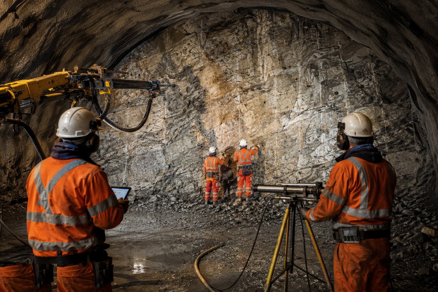
From the GI and probe drilling ahead of the face, classify the ground and fix the support classes and excavation sequence: advance length per round, the top heading–bench–invert staging, the sprayed lining thickness and reinforcement for each class, and the face support measures — face dowels, spiling, pre-treatment — where the ground cannot stand for the advance. The excavation and support plan is agreed with the designer and rehearsed; nobody improvises at an open face.
Step 2: Excavate the advance
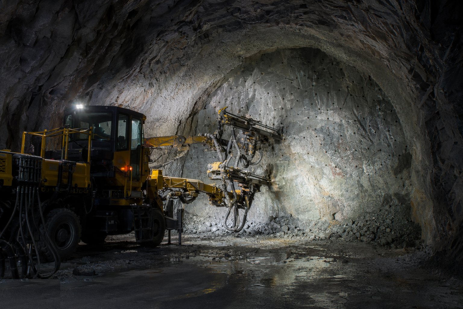
Take the advance with excavators fitted with breakers or roadheader attachments in SCL, or drill and fire the round in rock — in either case to the profile, with the minimum overbreak, because every void behind the lining has to be filled and every bulge eats clearance. In drill-and-blast, the round is drilled to the pattern, charged by certified shotfirers, and fired under exclusion; ventilation clears the fumes before re-entry. After blasting, scale the face and crown: loose rock is barred down before anyone works beneath it.
Step 3: Apply the primary support immediately
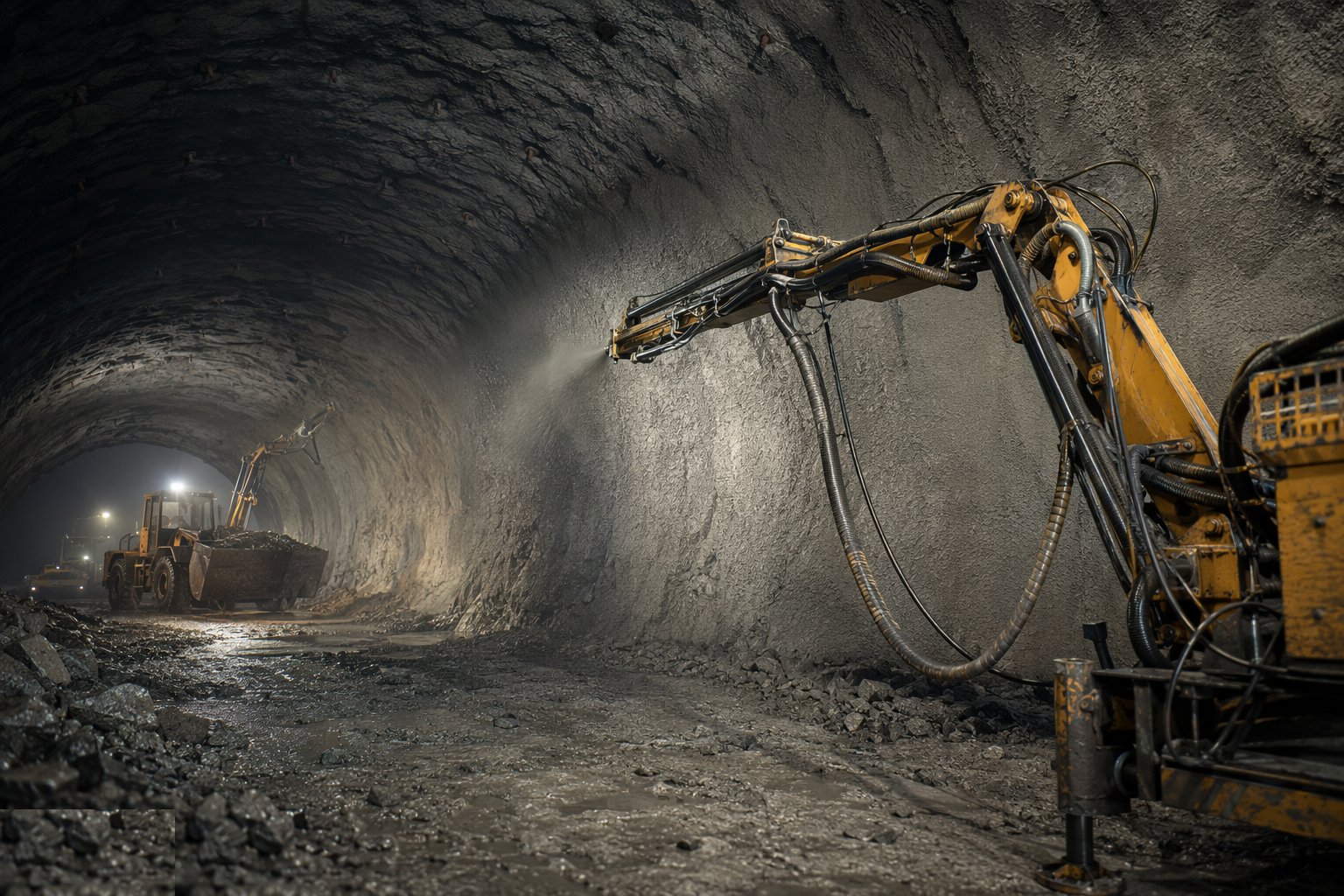
Support follows the face without delay: spray the first layer of shotcrete to seal the ground, erect lattice girders or arches and mesh, then build up the full lining thickness — sprayed in layers, with thickness checked by gauges and cores. In rock, install the pattern rock bolts and mesh and spray to the class requirement. Close the invert within the specified distance of the face: an open invert ring is an incomplete support, and the tunnel knows it.
Step 4: Monitor, interpret and respond
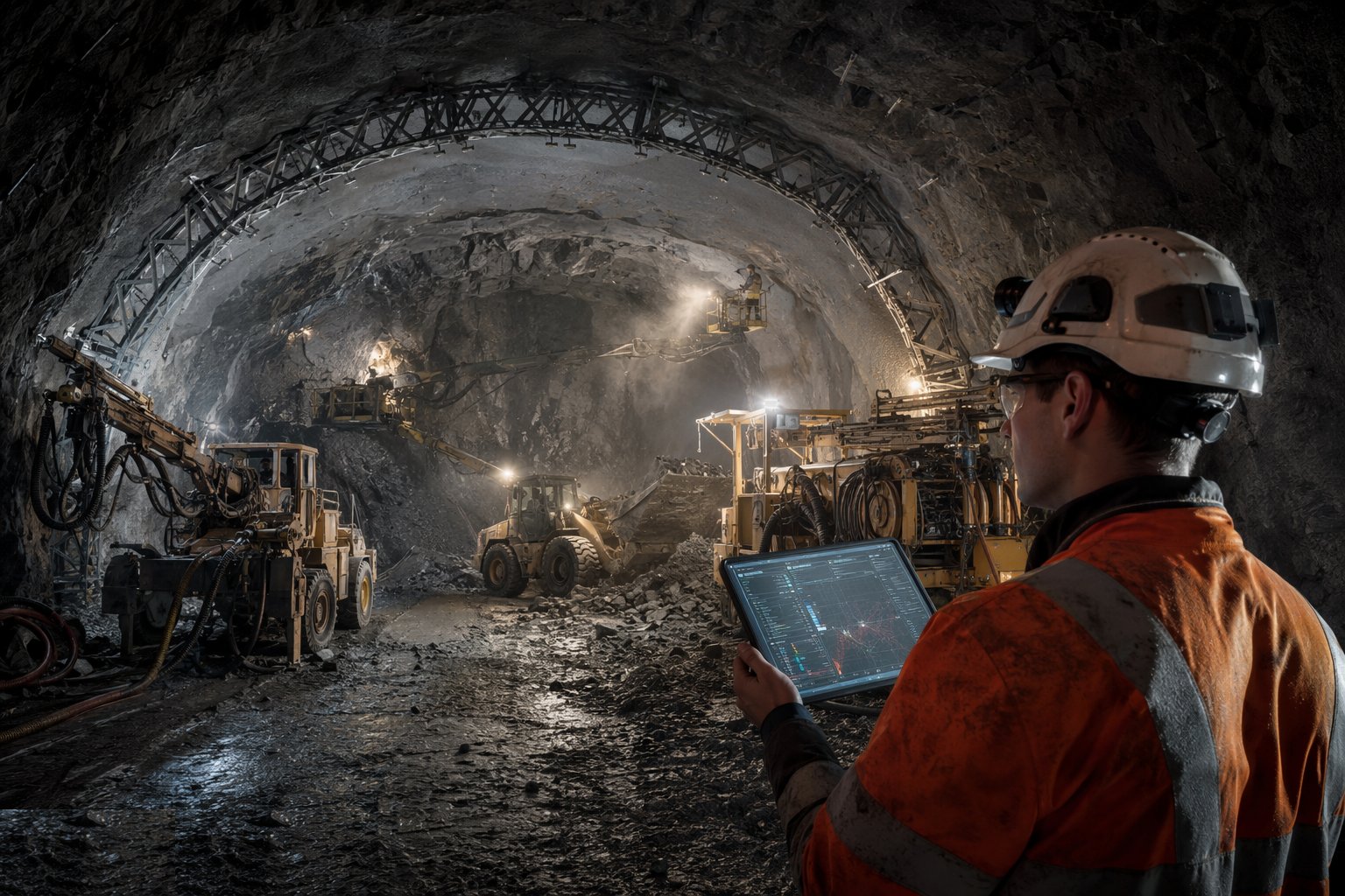
Install monitoring as the lining goes in — convergence pins, pressure cells, extensometers — and read it on the shift cycle. Plot movements against time and against trigger levels; the observational method only works if the readings change what you do: hold the advance, thicken the lining, add bolts, shorten the round. Face logging continues throughout — the exposed ground is mapped and photographed every round, feeding the record and the next decision.
Step 5: Install the waterproofing membrane (two-pass SCL)
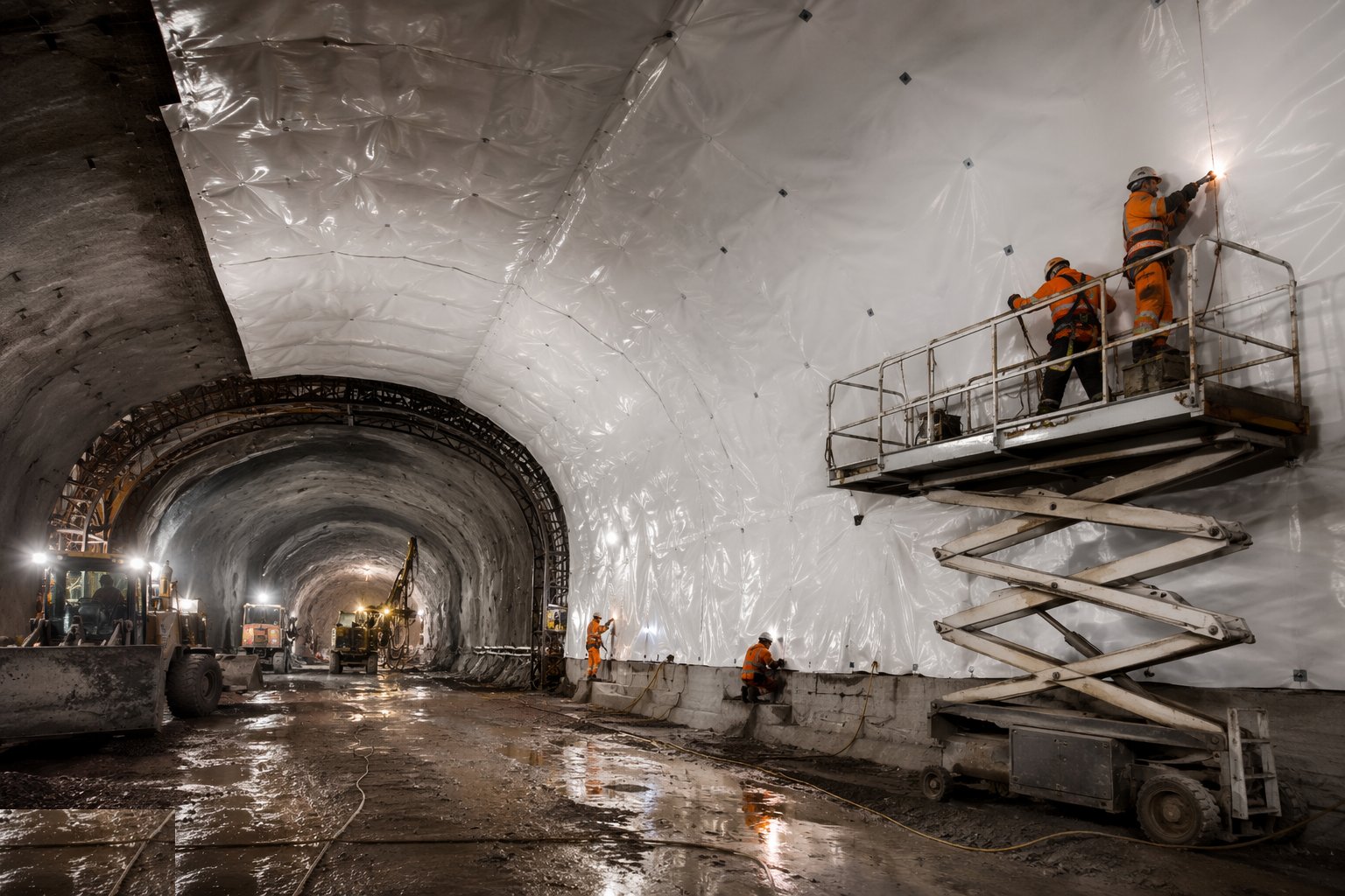
Once the primary lining is complete, sprayed smooth (regulating layer) and surveyed for clearance, fix the waterproofing system: a fleece-backed sheet membrane — typically PVC or EVA-based — welded in panels to the profile, divided into compartments by waterstop bulkheads, with injection hoses so any future leak can be grouted within its compartment. Every weld is tested; the membrane is protected at the invert and at reinforcement zones, because a membrane punctured by a flying bar end leaks for a century.
Step 6: Cast the secondary lining and invert
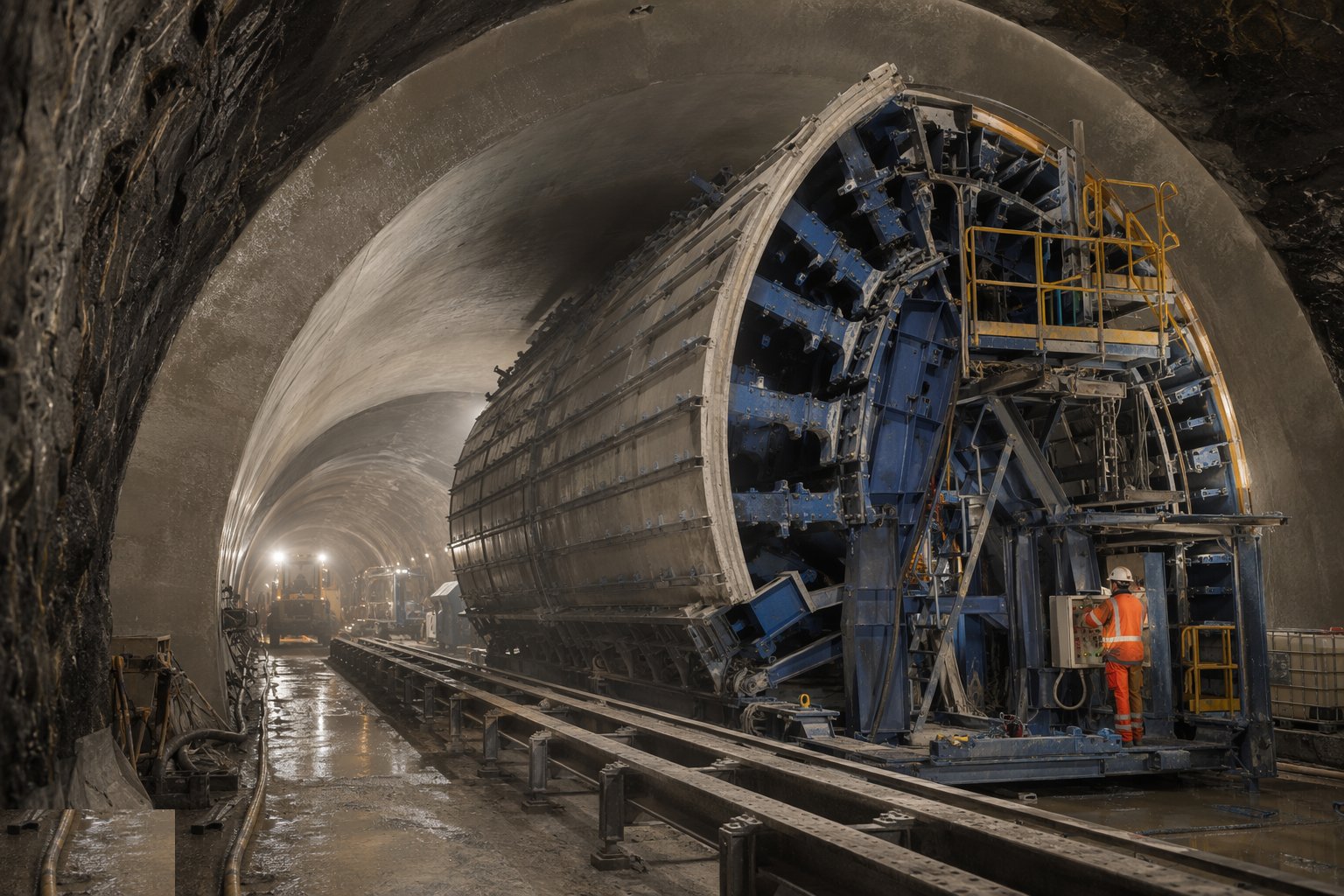
Fix the secondary lining reinforcement inside the membrane — spacers and handling detailed so nothing punctures it — and pour the cast in situ lining from travelling formwork, typically in bays of a manageable length, starting with the invert so the ring closes properly. Concrete is placed and vibrated against the membrane with care, cured, and the formwork struck on strength. Construction joints get waterstops; the completed lining is surveyed for the final clearance envelope before fit-out.
Step 7: Grout, drain and hand over the structure
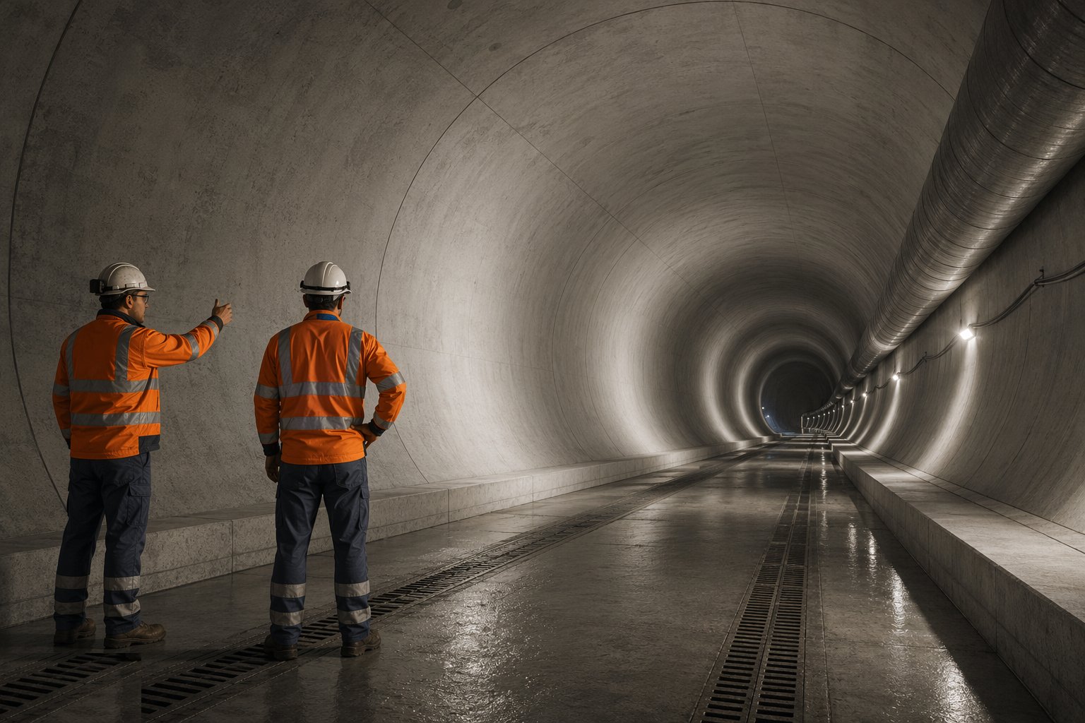
Contact-grout any voids between lining and ground, prove the drainage paths the design relies on, and pressure or flow test the waterproofing compartments where specified. Inspect the finished tunnel: lining defects logged and repaired, water ingress measured against the specified limit, as-built surveys and records — ground classes, support installed, monitoring histories, membrane test certificates — compiled into the handback file the asset owner will live with for the next hundred years.
Plant and equipment
- Excavators with breakers and roadheader attachments for SCL advances
- Shotcrete robots and spraying rigs; batching and accelerator dosing
- Lattice girder and mesh handling equipment
- Drilling jumbos, charging equipment and explosives stores for drill-and-blast
- Scaling rigs and mucking loaders with haul trucks or conveyors
- Membrane welding kit and weld test equipment; injection hose systems
- Travelling formwork for secondary lining; concrete pumps
- Monitoring: convergence pins, tape/extensometers, pressure cells, data loggers
Quality control checks
- Shotcrete compliance: panel tests, cores for strength and thickness, accelerator dosage records
- Support installed per class: bolt pull tests, girder positions, lining thickness surveys
- Face logs every round; support class changes recorded and countersigned by the designer
- Monitoring plotted daily against trigger levels with actions recorded
- Membrane weld tests (air channel or equivalent) per seam; compartment boundaries recorded
- Secondary lining concrete records, waterstop installation checks, clearance surveys
- Water ingress measured against the specified tightness before handback
Safety considerations
- Open-face work: support installed before anyone works under unsupported ground — no exceptions, ever
- BS 6164 tunnelling discipline: ventilation, gas monitoring, dust control (respirable silica from spraying and blasting), refuge and communications
- Shotfiring: certified shotfirers, exclusion and clearance before firing, misfire procedures drilled
- Scaling before entry after every blast; mechanical scaling preferred over hand barring
- Spraying operations: rebound and accelerator burns, eye and skin protection, ventilation at the face
- Membrane welding fumes and hot work underground; secondary lining formwork and pour operations at height
- Ground treatment chemicals (grouts, resins) handled under COSHH with spill containment
Common defects
- Overbreak voids left ungrouted behind the lining — load concentrates, lining cracks
- Shotcrete rebound buried in the lining: weak pockets found by cores at handback
- Invert closed late: convergence runs away while the crew works the heading
- Membrane punctured by reinforcement or formwork — leaks appearing compartment by compartment
- Monitoring read but not acted on: the amber trigger passed without the designed response
- Waterstops displaced during the secondary pour: construction joints weep permanently
- Face logged optimistically: a support class carried one round too far into worse ground
Best suited for
- Short tunnels, junctions and enlargements where a TBM cannot fit
- Variable ground needing flexible, observational support
- Rock drives on the drill-charge-fire-muck cycle
- Cross-passages and connections off a main drive
How long does SCL & Drill-and-Blast Tunnelling take?
Typical duration: SCL advances typically run 1–2 m per day per face, so a station cavern or short tunnel is months of excavation plus membrane and secondary lining; drill-and-blast typically achieves one to two rounds per day per face..