Water Pumping Stations
Civil engineering built around machines — wet wells and dry wells as the concrete, pumps lifted, set and laser-aligned on their plinths, surge vessels taming the pressure waves, the full M&E fit-out with standby power, and witnessed performance tests proving the duty before the network trusts it.
Last updated 2026-07-28 by the BuildPedia Editorial Team.
What is Water Pumping Stations?
A water pumping station is a concrete structure that exists to serve rotating machinery, and it succeeds or fails on how well the civil work understood that. The classic arrangement splits the station in two: the wet well, a water-retaining chamber where the incoming main delivers and the pumps draw, and the dry well beside or below it where the pumps, valves and pipework stand in conditions a fitter can work in — connected through the wall by suction pipework and separated by it from the water. The wet well is hydraulic design in concrete: its geometry, depth and suction bell clearances are set to the Hydraulic Institute intake standards, because a badly shaped sump breeds vortices, vortices feed air to pumps, and air-fed pumps cavitate themselves to an early grave. Submersible stations skip the dry well and hang the pumps in the wet one on guide rails; booster stations sit inline on the main; high-lift stations run vertical turbine or horizontal split-casing sets depending on the duty.
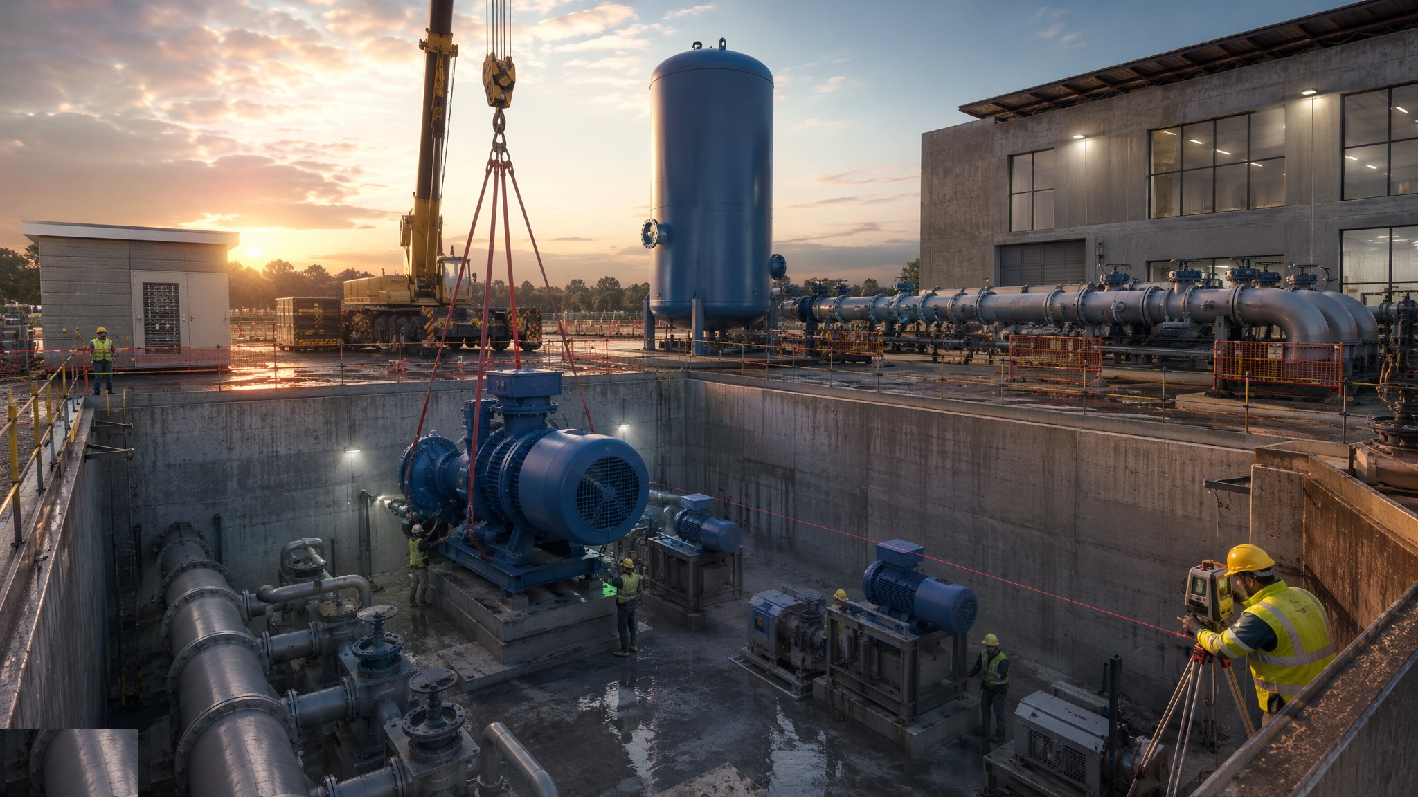
The civil works are water-retaining concrete to BS 8007 where the chambers hold water, with the flotation check watching every empty chamber near a water table. Then the mechanical installation begins, and the tolerances change language: pumps are lifted into chambers by crane or the station's own lifting beams, set on plinths and baseplates, levelled and laser-aligned to their motors within hundredths of a millimetre, and grouted on non-shrink grout that has to carry vibration for decades. Suction and discharge pipework is erected without imposing strain on the pump flanges — pipework fitted to the pump, never the pump dragged to the pipework — and valves, non-return valves and flow metering complete the hydraulic train. The surge vessel, a pressure vessel with a membrane or bladder, stands ready to absorb the pressure wave when a pump trips: the station's insurance against the water hammer that splits rising mains.
The M&E fit-out turns the structure into a station: switchgear and motor control centres, variable speed drives matching pump speed to demand, level control in the wet well, instrumentation and the telemetry outstation that ties the site into the water company's control room. Standby power — a generator with automatic transfer switch, or a second supply — answers the question every pumping station must: what happens to supply when the power fails. And the whole assembly is proven in the only currency that counts: witnessed performance tests, pump by pump and duty by duty, measuring flow, head, power and vibration against the guaranteed duty points to BS EN ISO 9906 acceptance grades, with the duty/standby changeover, surge response and power-failure sequences all exercised before the client's witness. A pumping station that has passed its witnessed tests is an asset; one that has merely been switched on is an anecdote waiting for its first failure.
When and why is Water Pumping Stations used?
Pumping stations are built wherever gravity declines to do the work: lifting treated water to high-level zones and reservoirs, boosting pressure at the edges of the network, feeding rising mains across ridges, and transferring between supply zones. The configuration follows the duty — wet well/dry well for maintainability on the big sets, submersibles for compact footprints, inline boosters where the main itself is the sump. It matters because the station is a single point of failure wearing a fence: misaligned pumps vibrate bearings to death in months, an undersized wet well cavitates the fleet, a failed surge vessel invites the hammer that bursts the main at 2 a.m., and a standby generator that never starts on test will certainly never start in a storm. The witnessed test regime exists because the water industry learned all of this the expensive way — the contractor's job is to build the station that passes it first time and then bores its operators for forty years.
Types of Water Pumping Stations
Wet well / dry well stations
Separate water-retaining sump and accessible pump chamber, with horizontal or vertical sets drawing through the dividing wall. The maintainable classic: dry feet, full access, and the configuration big raw and treated water stations grow into.
Submersible wet well stations
Pumps on guide rails in the wet well itself, lifted for maintenance by the station's hoist. Compact and quiet, with no dry well to flood — the standard answer for smaller duties and tight sites.
Inline booster stations
Pumps in series with the main in a chamber or above-ground kiosk, raising pressure without a sump. The network's pressure patch: simple hydraulics, demanding alignment and surge control all the same.
High-lift stations with vertical turbine sets
Vertical line-shaft or can pumps drawing from deep wells or sumps for the big heads. Precision machines in precision concrete: shaft alignment and sump geometry decide the station's working life.
Package and small booster sets
Factory-assembled skid or chamber-mounted sets for developments and small zones. Standardised plant, same rules: foundations true, pipework unstressed, commissioning witnessed.
Water Pumping Stations: step by step
Step 1: Construct the wet well and dry well
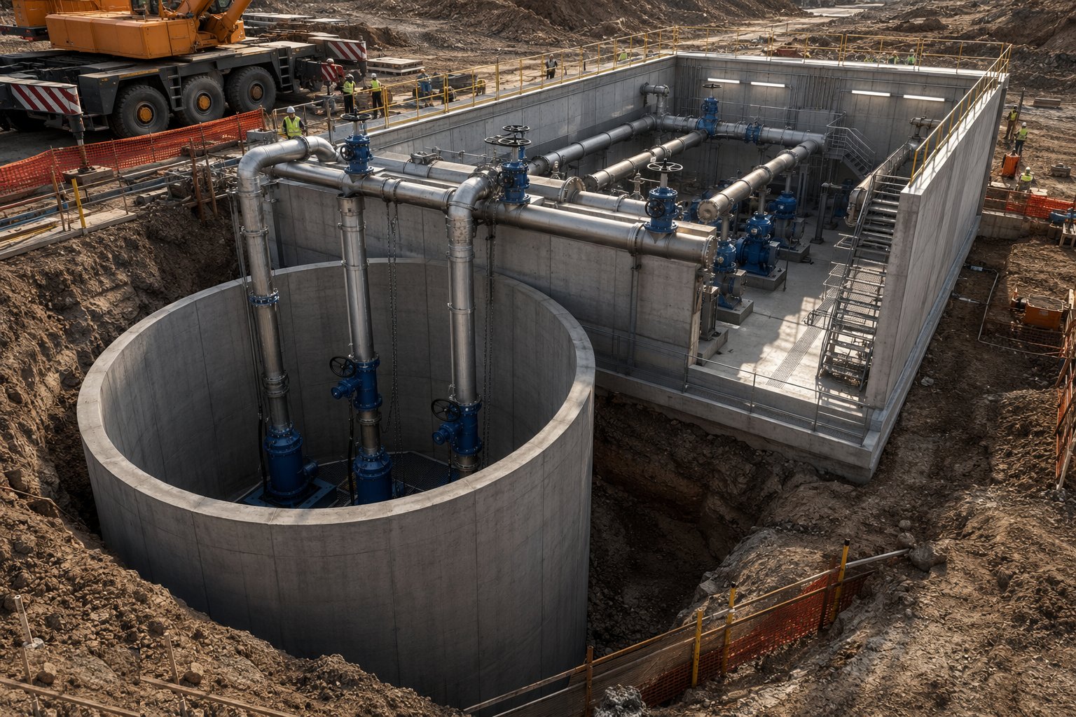
The chambers are excavated and supported — sheet-piled or caisson-sunk where the ground and the water table demand — and the water-retaining concrete is cast to BS 8007 discipline: base, walls and roof with waterstops at the joints and puddle-flanged penetrations cast in for every suction, discharge and drain pipe. The wet well's internal geometry is built to the hydraulic design: benching, fillets and suction bell positions to drawing, because the vortex that cavitates the pumps was designed or prevented right here, in the concrete, years before the first impeller turns.
Step 2: Install the pipework, valves and penstocks
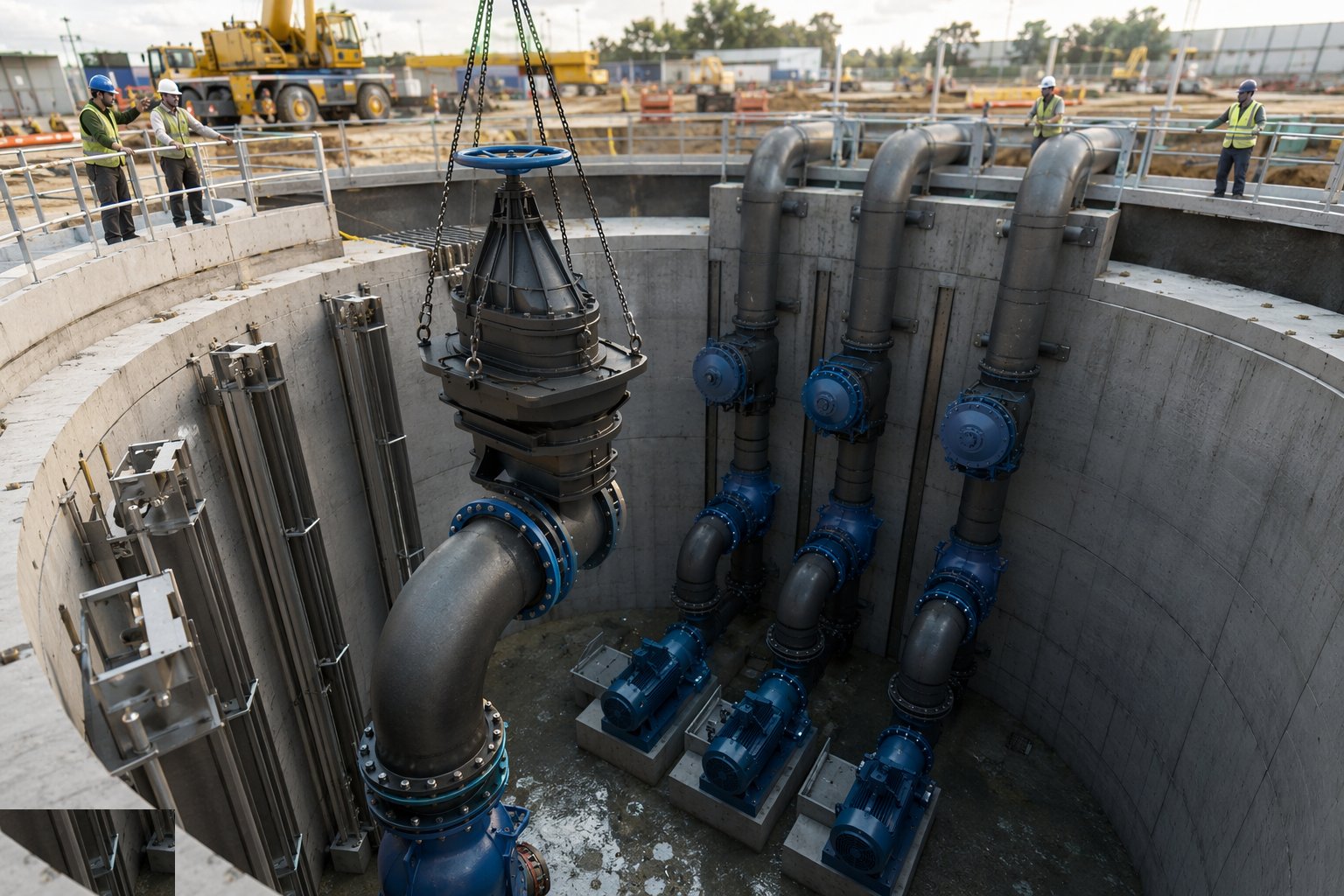
Suction and discharge manifolds are erected on their supports with every flange pulled up true and every pipe run fitted so it carries its own weight — the pump nozzles are alignment datums, not anchors. Non-return valves, isolating valves, air valves and flow meters go in per the hydraulic train, pipework is pressure tested section by section, and the wet well fittings — penstocks, level instruments, screens where fitted — are set and operated through their full travel before water is invited.
Step 3: Set, align and grout the pumps
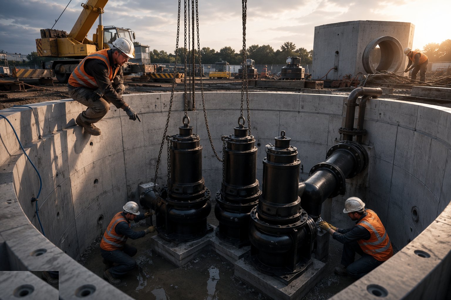
Pump sets are lifted in by crane through the roof openings or lowered on the station's beams, landed on their baseplates, levelled on shims or chocks and laser-aligned — coupling alignment to the manufacturer's tolerance, checked in both planes, recorded and signed. Baseplates are grouted on non-shrink epoxy or cementitious grout with full contact and no voids, the alignment is rechecked after the grout cures, and the pipework is connected last with the dial gauges watching that nothing moves. Alignment drifted between setting and start-up is the seed of every vibration story the station will ever tell.
Step 4: Install the surge protection
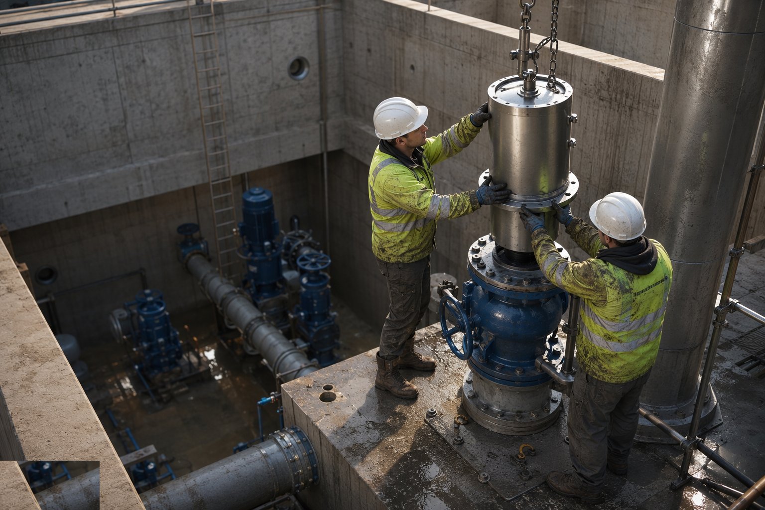
The surge vessel is set on its foundation, charged to its pre-charge pressure and connected to the discharge manifold, with the pressure relief valves and the non-return valve strategy commissioned to the surge analysis the design ran. Air valves on the rising main profile are checked at their high points. This equipment exists for the station's worst day — the power cut at full flow — and it is tested on a good day, because the water hammer does not schedule appointments.
Step 5: Complete the M&E fit-out and standby power
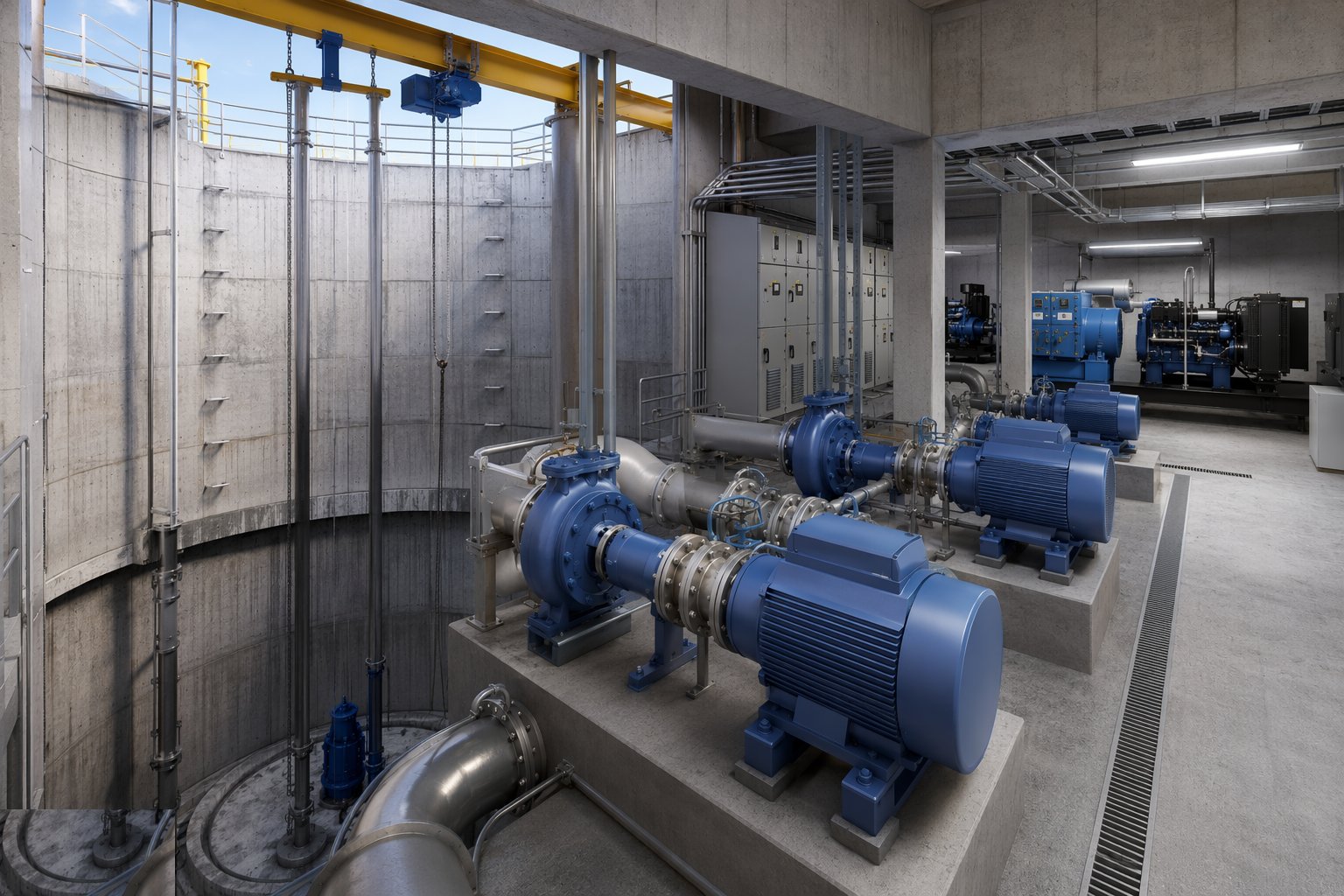
Switchgear and motor control centres are installed, terminated and tested; variable speed drives are commissioned with their parameters set to the hydraulic duty; level control, instrumentation and the telemetry outstation are wired and proven point to point with the control room. The standby generator is installed with its fuel system and automatic transfer switch, load-tested, and the mains-fail sequence exercised: power off, set started, load accepted, pumps running. Electrical certification accompanies every board, and the whole installation is tested as a system, not as a pile of certificates.
Step 6: Fill, flush and wet-test the hydraulics
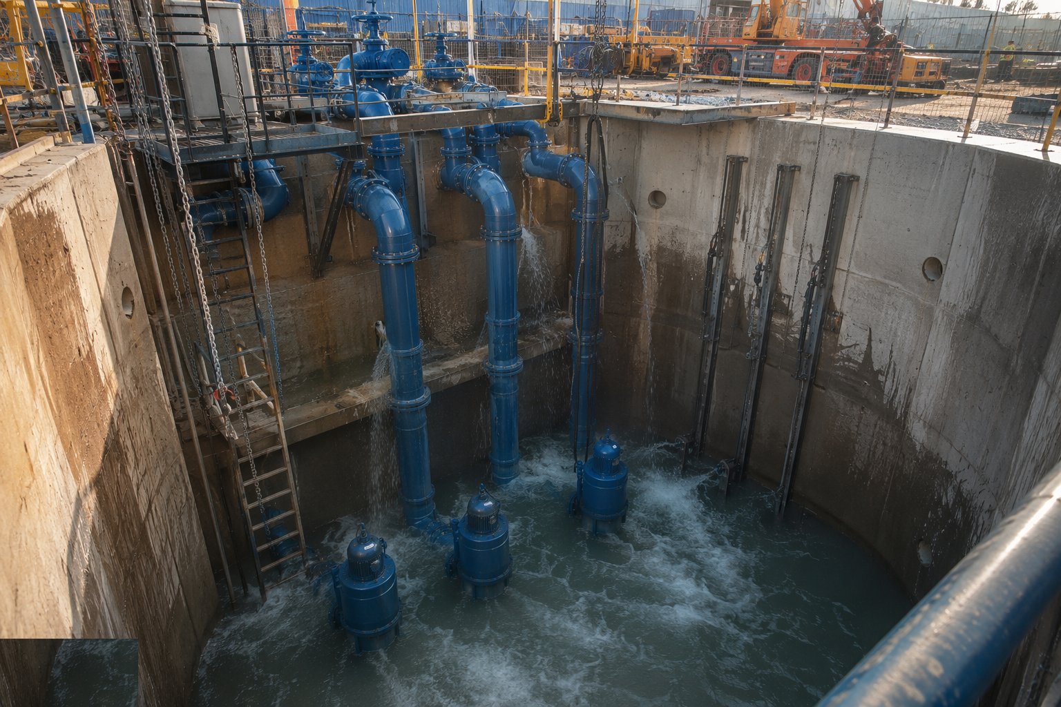
The station is wetted in sequence: wet well filled and the concrete watched, pipework proved under operating pressure, pumps bumped to confirm rotation, then run against closed and part-open valves to check the train. Leaks, noises and instrument readings are chased down before performance testing begins — the witnessed test is an examination, and nobody sits an examination with their shoelaces untied. Duty/standby selection, alarm chains and telemetry are all exercised in the wet.
Step 7: Run the witnessed performance tests and hand over
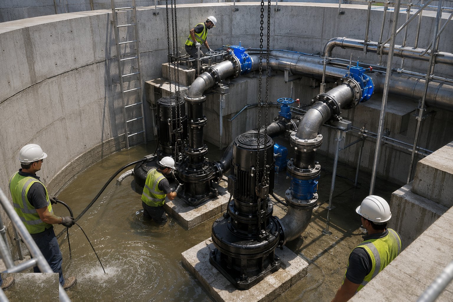
Pump by pump, the station is run at its duty points with the client's witness present: flow, head, power and vibration measured against the guarantee to BS EN ISO 9906, changeover between duty and standby demonstrated, surge response and power-failure sequences exercised, and every result recorded on the test sheets. The O&M manuals, test certificates, alignment and grout records, electrical certification and the FAT/SAT history are handed over with the keys, and the operations team is trained on the station they now own. A station that passes its witnessed tests first time has told you everything about how it was built.
Plant and equipment
- Excavation support: sheet piles, caisson sinking equipment and dewatering plant for deep chambers
- Cranes and the station's permanent lifting beams and hoists for pump installation
- Laser alignment equipment, dial gauges and precision levelling kit for pump setting
- Non-shrink grouting materials and equipment for baseplates
- Pipework fabrication and installation spreads with flange alignment tools
- Electrical test equipment; generator load banks for standby power proving
- Surge vessel charging and pressure testing equipment
- Flow, head, power and vibration measurement instruments for witnessed performance testing
Quality control checks
- Water-retaining concrete records and BS 8007 tightness tests on wet wells and below-ground chambers
- Pump alignment records: laser alignment at setting, after grouting and before start-up, all signed
- Grout records confirming void-free baseplate contact; plinth and foundation surveys
- Pipework pressure test certificates and flange alignment confirmations at the pump nozzles
- Electrical installation certification; generator load test and automatic transfer sequence records
- Witnessed performance test sheets to BS EN ISO 9906 — flow, head, power, vibration against guarantee
Safety considerations
- Deep chamber construction: excavation support, dewatering and flotation control for the empty station
- Confined space entry to wet wells and dry wells: permits, gas testing, ventilation and rescue provision
- Lifting heavy rotating machinery into deep chambers: engineered lifts, tag lines and exclusion below the load
- Electrical work on LV and HV switchgear: authorised persons, permits and test-before-dead discipline
- Stored energy: pressure in surge vessels and charged mains, and rotating machinery under test
- Lone working and remote site protocols once the station is live during commissioning
Common defects
- Pump misalignment after grouting or pipe strain at the flanges — vibration and bearing failures inside the first year
- Wet well geometry built off-drawing — vortices, air entrainment and cavitation the instruments diagnose as mystery noise
- Surge vessel with wrong pre-charge or failed membrane — the hammer that finds the weakest joint on the rising main
- Non-return valves slamming from wrong selection or poor installation — pressure spikes on every stop
- Level control and float failures flooding the dry well or running pumps dry — the instrumentation nobody point-to-point tested
- Standby generator failing the mains-fail test it was never given — discovered, of course, in a real outage
Best suited for
- Treated water lift and transfer stations feeding reservoirs and high zones
- Network booster stations raising pressure at zone boundaries
- Raw water intake and transfer pumping stations
- Rising main pumping over ridges and between catchments
- Replacement and refurbishment of life-expired station plant
How long does Water Pumping Stations take?
Typical duration: A medium pumping station — chambers, plant, M&E and witnessed testing — runs 9–18 months; deep chamber construction and long-lead switchgear and pumps set the pace, and the witnessed test programme at the end is scheduled with the client, not at the client..