Water Pipelines & Trunk Mains
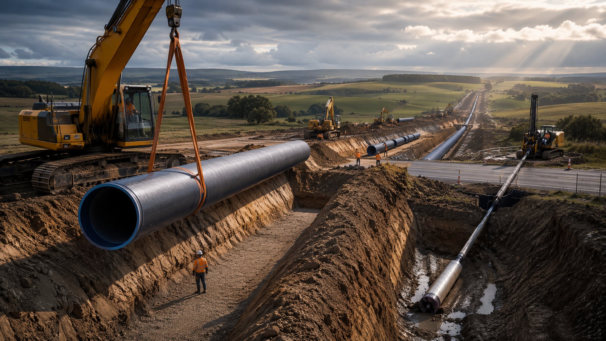
Long kilometres of buried pressure main — open-cut laying with bedding and surround, thrust boring and directional drilling under the obstacles, ductile iron, PE, steel and concrete pipe, thrust blocks at every bend, then pressure test, swab, chlorinate and connect to a live network that cannot go without water.
Last updated 2026-07-28 by the BuildPedia Editorial Team.
What is Water Pipelines & Trunk Mains?
A trunk main is a pressure vessel hundreds of kilometres long, buried in ground that never stops moving. The materials each carry their own grammar: ductile iron to BS EN 545 with push-fit spigot-and-socket joints, forgiving and robust and the industry's default; polyethylene to BS EN 12201, butt-fused or electrofused into a continuous string, flexible enough to be pulled into drilled holes; steel to BS EN 10224, welded and wrapped, for the big diameters and high pressures; and prestressed concrete cylinder pipe for the largest strategic mains. Open-cut laying is the honest core of the work: trench excavated and supported, bedding laid and levelled, pipe lowered and jointed, surround placed and compacted by hand around the barrel, and backfill compacted in layers above — with thrust blocks cast at every bend, tee and valve where the water's pressure tries to push the joint apart, sized against the bearing of the ground and left to gain strength before the line sees pressure.
Where the trench cannot go — motorways, railways, rivers, live services and the gardens of the litigious — the main goes in trenchless. Thrust boring and auger boring push a steel sleeve under the obstruction with the product pipe installed inside; horizontal directional drilling reams a pilot bore and pulls a fused PE string back through; pipe jacking drives a culvert for the main to pass through; and slip-lining and close-fit linings renew old mains from the inside. Each method trades cost against disruption, and each has its failure signature: overbreak and settlement above a badly steered bore, a fused joint dragged past its limit, an annulus grout that never quite filled. The trenchless length is engineered metre by metre because nobody will see it again until something goes wrong.
The main is not finished when it is buried — it is finished when it is proven. The pressure test to BS EN 805 fills the line, lets it stabilise, then holds it at test pressure while the allowable water loss arithmetic decides pass or fail; air is the enemy of the test and the sworn duty of every air valve on the profile. Swabbing pushes foam pigs through to clean the bore; chlorination disinfects the main, stands its contact time and is flushed; and bacteriological samples taken by the water company decide whether the pipe may carry drinking water. Then comes the part that separates the mainlayers from the theorists: the connection to the live network — under-pressure tees drilled onto a charged main, or planned cut-ins during shutdowns agreed with the operations team — made so that not one customer notices the day the new main joined the grid.
When and why is Water Pipelines & Trunk Mains used?
Pipeline works run on new strategic mains and distribution extensions, on renewals of ageing iron, and on the diversion schemes every road and rail project drags behind it. Method and material are chosen on ground, pressure, obstruction and the client's standards — ductile iron for robustness, PE for trenchless and speed, steel for diameter and pressure. It matters because a water main is a promise made under pressure: a leaking joint is treated water lost and a road dug twice, a failed chlorination is a public health conversation nobody wants, and a live connection fumbled is a supply interruption on the evening news. The margins in mainlaying are thin and the rates are won by crews who lay true, test first time and chlorinate clean — the whole craft is doing buried work to a standard the surface will never show.
Types of Water Pipelines & Trunk Mains
Open-cut ductile iron mains
DI pipe to BS EN 545 with push-fit joints on prepared bedding, anchored by thrust blocks at fittings. The industry default: tolerant, repairable, and honest about the ground it lies in.
PE systems, butt-fused and electrofused
Polyethylene to BS EN 12201 welded into continuous strings, laid open-cut or pulled into bores. Corrosion-free and jointless over distance — with fusion traceability that lives or dies on operator discipline.
Steel and prestressed concrete trunk mains
Welded steel to BS EN 10224 and prestressed concrete cylinder pipe for the largest diameters and pressures. Heavy engineering in a trench: every weld tested, every wrap inspected, every metre logged.
Trenchless crossings — thrust bore, auger and HDD
Sleeves bored under roads and railways, or PE strings pulled through reamed directional bores. The method for obstacles that cannot be opened: slower per metre, cheaper per headache.
Rehabilitation — slip-lining and close-fit lining
New PE inserted into failing mains, or folded and expanded liners restoring the bore from inside. Renewal without the trench: the network rebuilt through its own access chambers.
Water Pipelines & Trunk Mains: step by step
Step 1: Prove the route: trial holes, services and survey
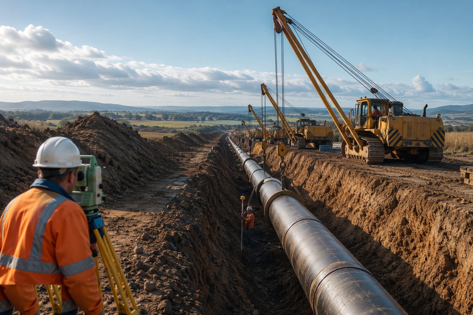
The line is walked before it is dug: trial holes at crossings and doubtful ground, CAT scans and permit-to-dig discipline against the services the drawings swear are there and the ones they do not, and the route surveyed and pegged with depths checked against the design cover. Landowners, highway authorities and the utilities whose plant crosses the line are all engaged before the first trench — a main laid through someone else's infrastructure without agreement is a claim with a chainage.
Step 2: Excavate and support the trench
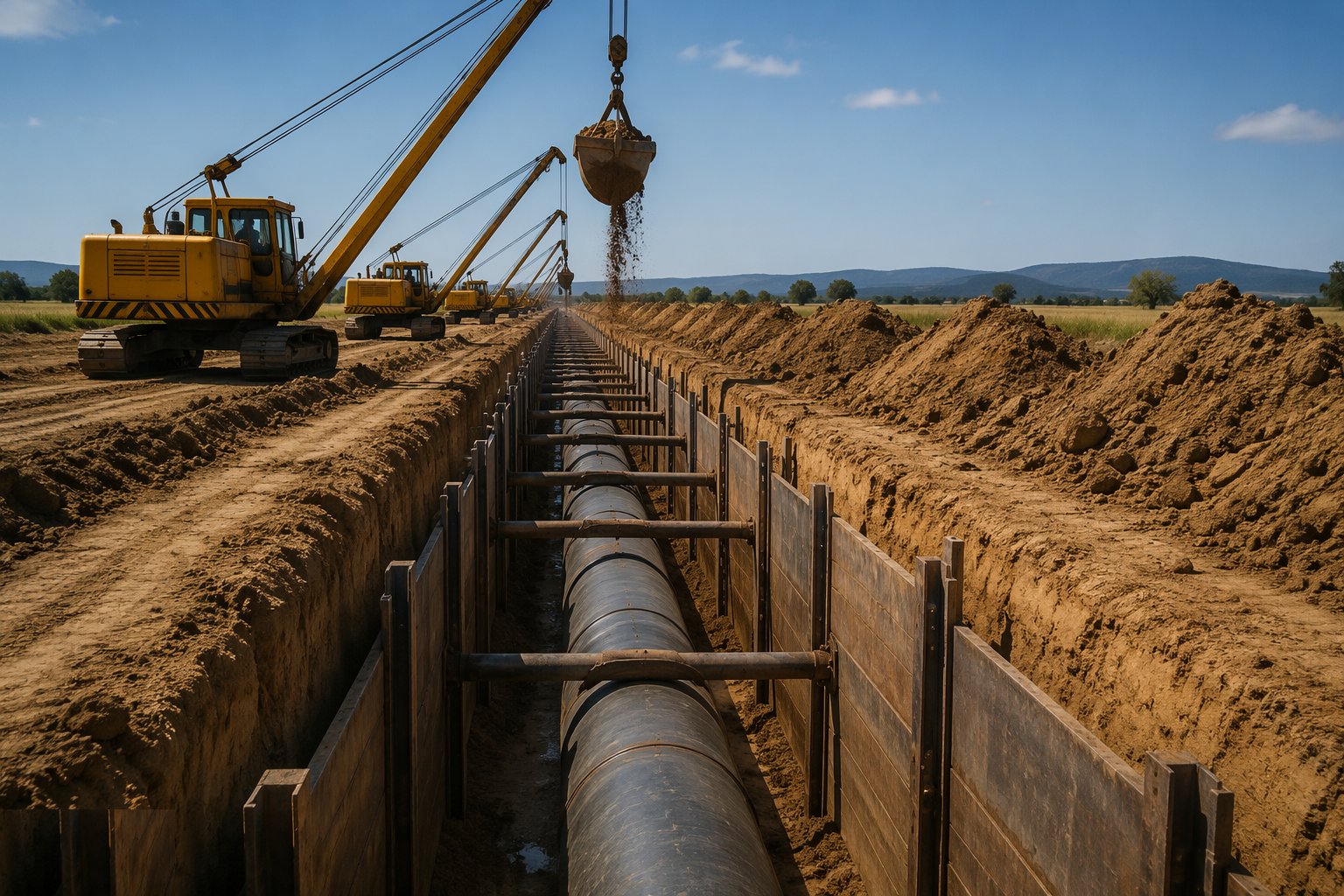
Trench excavation runs at laying pace — not metres ahead of the gang but with it — supported by trench boxes, sheets or battering as the ground demands, with edges protected and ladders at working depth. The trench bottom is trimmed and inspected: soft spots dug out and replaced, rock excavated below grade and made up with bedding, and water kept from ponding where the pipe will lie. A main is only as straight and true as the bottom it was laid on.
Step 3: Lay and joint the pipe
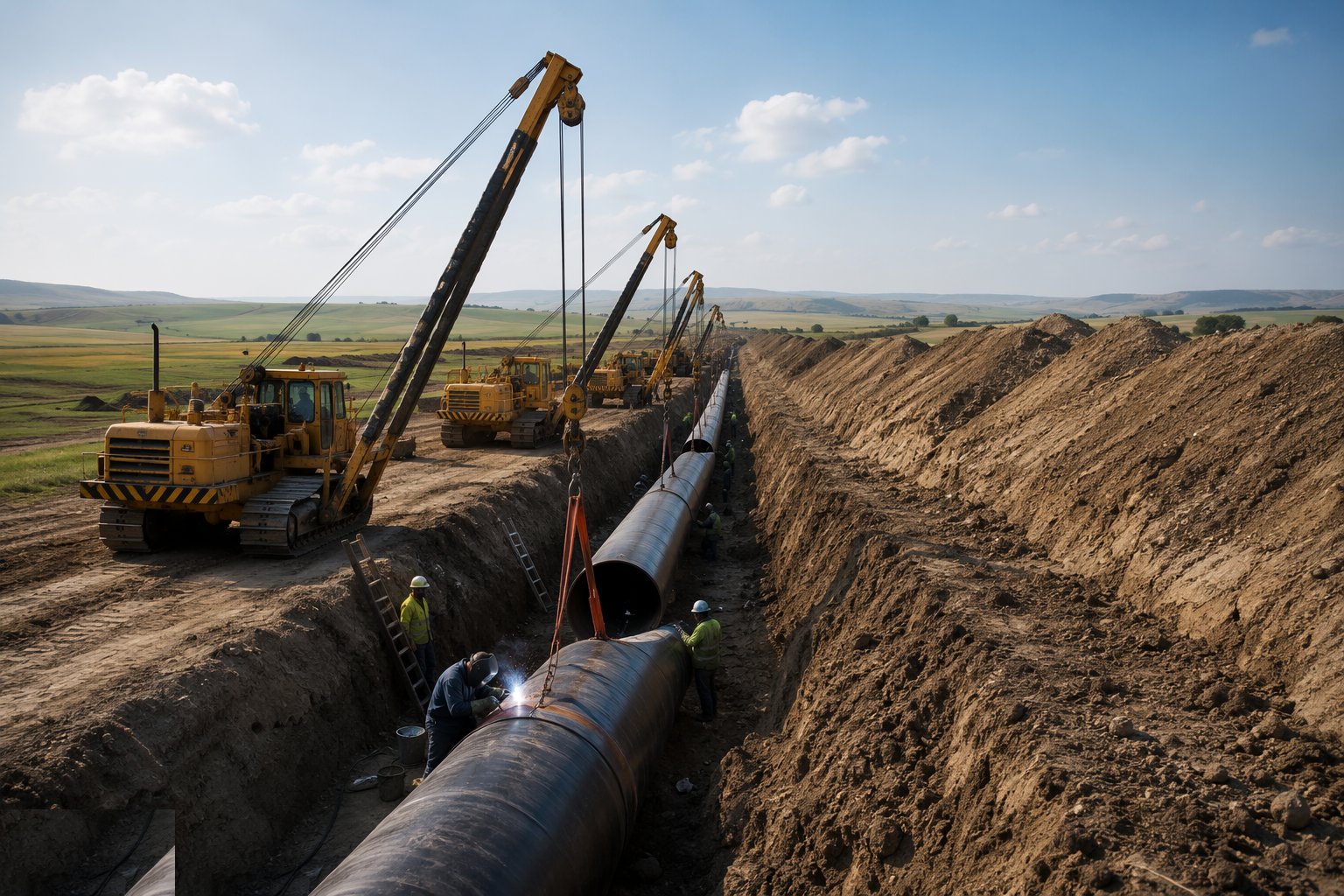
Bedding is placed and levelled, pipes lowered by machine — never dropped, never dragged — and jointed per the material: sockets lubricated and homed to the mark on DI, fusion joints made, logged and traced on PE, welds made and tested on steel. Pipes are laid to line and level with deflections inside the manufacturer's limits at every joint, and the surround is placed and compacted by hand around the barrel so the pipe is cradled, not perched. Every joint is recorded; the buried record is the only one that will ever matter.
Step 4: Anchor the line: thrust blocks and restrained joints
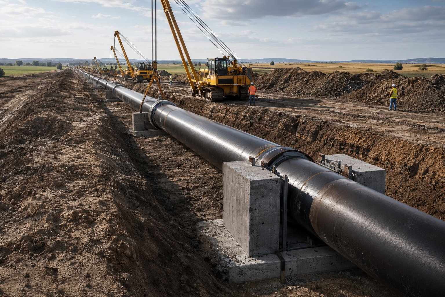
At every bend, tee, taper and closed valve the hydraulic thrust is calculated and carried: concrete thrust blocks cast against undisturbed ground sized for the bearing pressure, or restrained-joint systems where blocks cannot go. Blocks are cast around wrapped fittings — concrete bears on ground, never on the joint itself — and the line is not pressurised until the concrete has the strength to take it. The impulse to test early against green concrete is how joints separate at midnight.
Step 5: Cross the obstacles trenchless
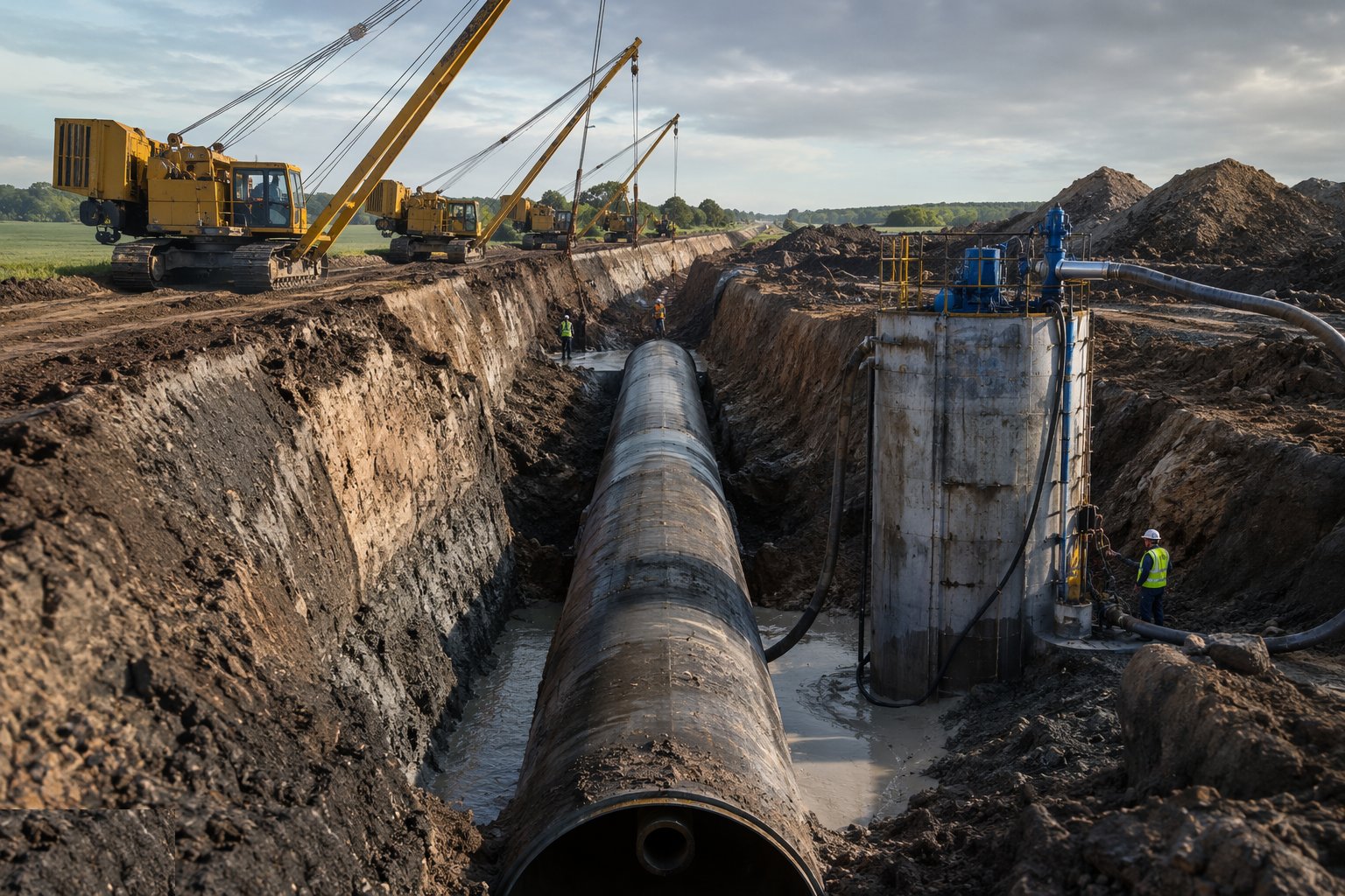
Thrust and auger bores drive their sleeves from shafts dug either side of the obstruction, with line and level checked at the face and the annulus grouted after the product pipe is installed. Directional drills steer the pilot, ream the bore and pull the fused string home in one continuous operation, with pulling loads monitored against the pipe's limits. Every trenchless metre is logged — steering records, grout records, fusion data — because the crossing is the length of main nobody will ever inspect again.
Step 6: Backfill, reinstate and mark
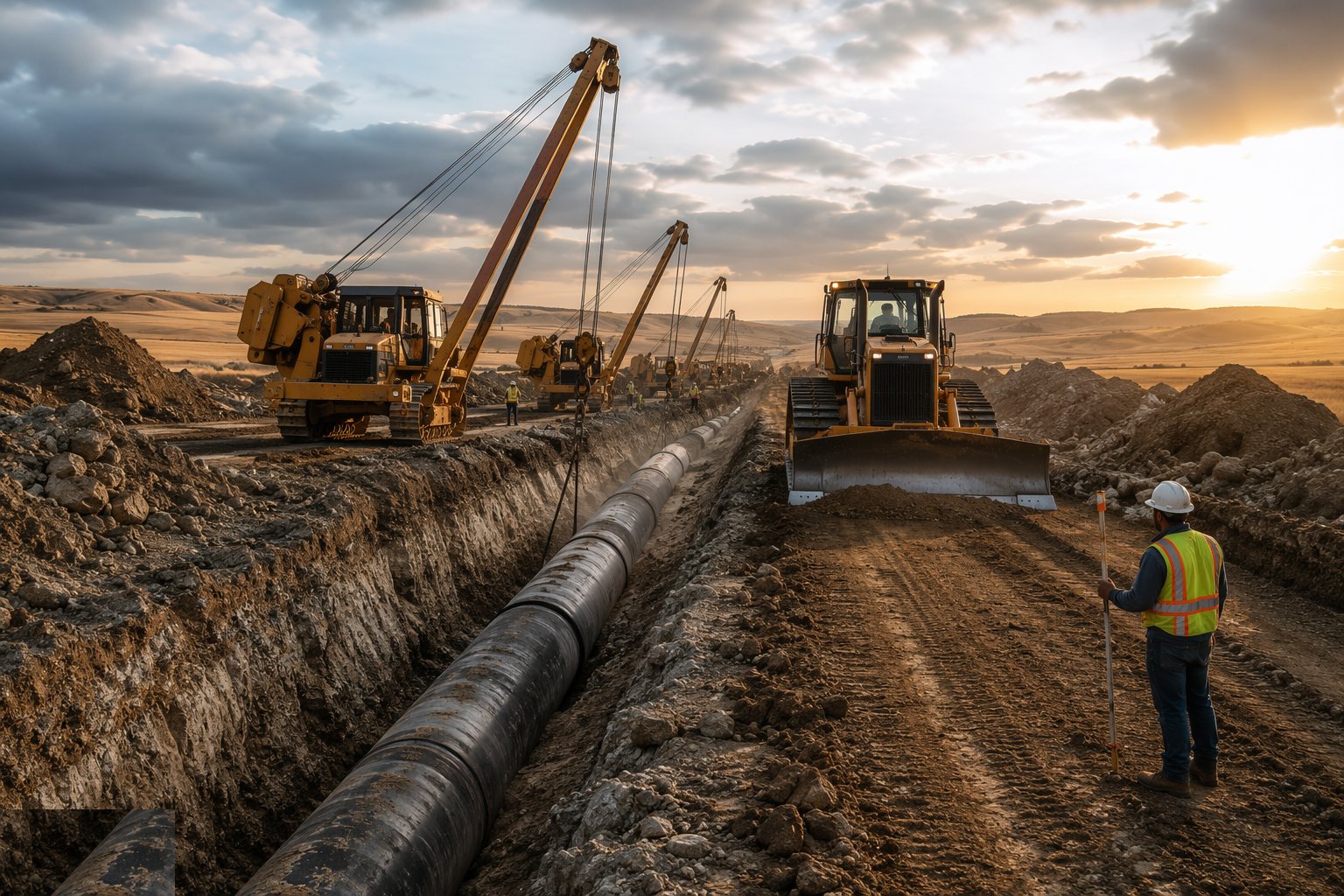
Backfill goes in compacted layers — selected material around the pipe, excavated or imported above — with compaction tested in roads and footways to the reinstatement specification, and warning tape and marker posts set over the line. Reinstatement is done to the highway authority's standard because the trench's public face is the road surface, and a sunken reinstatement is the water industry's most visible signature. As-built records are taken as the trench closes: line, level, fittings and every joint's position.
Step 7: Pressure test, swab and chlorinate
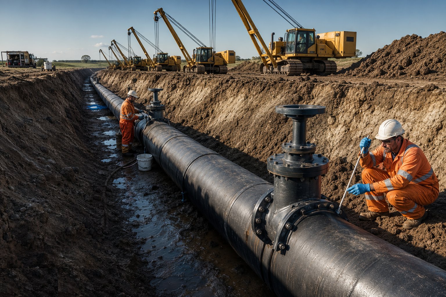
The laid section is filled slowly against open air valves, stabilised, and pressure tested to BS EN 805 — test pressure held, water loss measured and judged against the allowable. Foam swabs are driven through to clean the bore, the main is chlorinated to the specified dose and contact time, flushed to the discharge consent, and bacteriological samples taken. Failures are chased systematically — test sections shortened, joints exposed — because a main that will not hold pressure or pass sampling is not a main yet, whatever the programme says.
Step 8: Connect to the live network
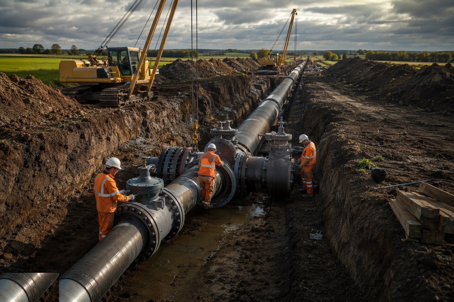
Connections are made on the water company's terms: under-pressure tees drilled onto charged mains through tapping valves, or cut-ins executed inside agreed shutdowns with customers notified and tankers standing by if the window slips. The new main is proven, disinfected and sampled before it is allowed to feed the network; the connection is made, the valves opened in their sequence, and the telemetry confirms flow the design promised. The measure of the job is the silence — nobody downstream ever knowing it happened.
Plant and equipment
- Excavators with trench boxes, sheets and drag boxes for supported open-cut laying
- Pipe lasers, levels and total stations for line and grade control
- Butt-fusion and electrofusion equipment with logged joint data for PE
- Thrust boring and auger boring rigs; directional drilling spreads with steering and tracking
- Pipe handling kit: slings, side booms and lowering-in equipment matched to the pipe
- Pressure test pumps, test rigs and calibrated gauges to BS EN 805
- Swabbing, chlorination and sampling equipment; dosing and dechlorination kit
- Under-pressure tapping machines and line-stop equipment for live connections
Quality control checks
- Bedding, surround and backfill compaction records against the reinstatement specification
- Joint records per pipe: DI jointing checks, PE fusion logs with operator traceability, steel weld NDT
- Thrust block records: dimensions, bearing face, concrete strength before pressurisation
- Trenchless logs: steering records, pulling loads and annulus grouting volumes per crossing
- BS EN 805 pressure test certificates per section; chlorination certificates and bacteriological results
- As-built line and level records with fitting positions, lodged with the water company before handover
Safety considerations
- Trench collapse as the standing killer: support or batter every excavation, inspect daily, ladder access at depth
- Buried and overhead services: CAT scans, permit to dig and trial holes before the bucket
- Pipe handling and lowering-in: slings rated and inspected, exclusion under suspended pipe, fingers out of sockets
- Pressure testing hazards: stored energy in a charged main, exclusion zones at ends and fittings, controlled filling
- Chlorine handling and dosing: chemical PPE, ventilation and emergency procedures briefed to the gang
- Live-network connections: operations coordination, water hygiene discipline and hygiene passports for drinking-water work
Common defects
- Joint leaks from deflected sockets, poor bedding or surround compacted by machine instead of by hand
- Thrust blocks undersized, cast against made ground, or pressurised green — joint separation at the first surge
- Pressure test failures hunted section by section: air in the line, leaking fittings, the joint someone knew about
- Failed bacteriological samples from poor swabbing or contaminated fittings — re-chlorinate, re-sample, re-explain
- PE fusion joint failures traced to skipped scraping, misalignment or an operator without traceability
- Trench settlement in the highway — the reinstatement that sinks a year later with the contractor's name on it
Best suited for
- New trunk mains and strategic transfer pipelines
- Distribution main laying and renewal programmes
- Trenchless crossings of motorways, railways and rivers
- Diversions for road, rail and development schemes
- Rehabilitation of ageing mains by lining and slip-lining
How long does Water Pipelines & Trunk Mains take?
Typical duration: Open-cut laying runs 50–150 m per week per gang depending on diameter and ground; a 5–10 km trunk main scheme with crossings, testing and connections is a 12–30-month programme, and the chlorination and connection windows at the end belong to the water company, not to the contractor's ambition..