Water Treatment Works Construction
Concrete boxes that must hold water and clean it — water-retaining tanks to BS 8007 and EN 1992-3, filters and clarifiers with their underdrains and nozzles, process pipework and valves threaded between them, washwater recovery, and a tightness test that decides whether the tank exists at all.
Last updated 2026-07-28 by the BuildPedia Editorial Team.
What is Water Treatment Works Construction?
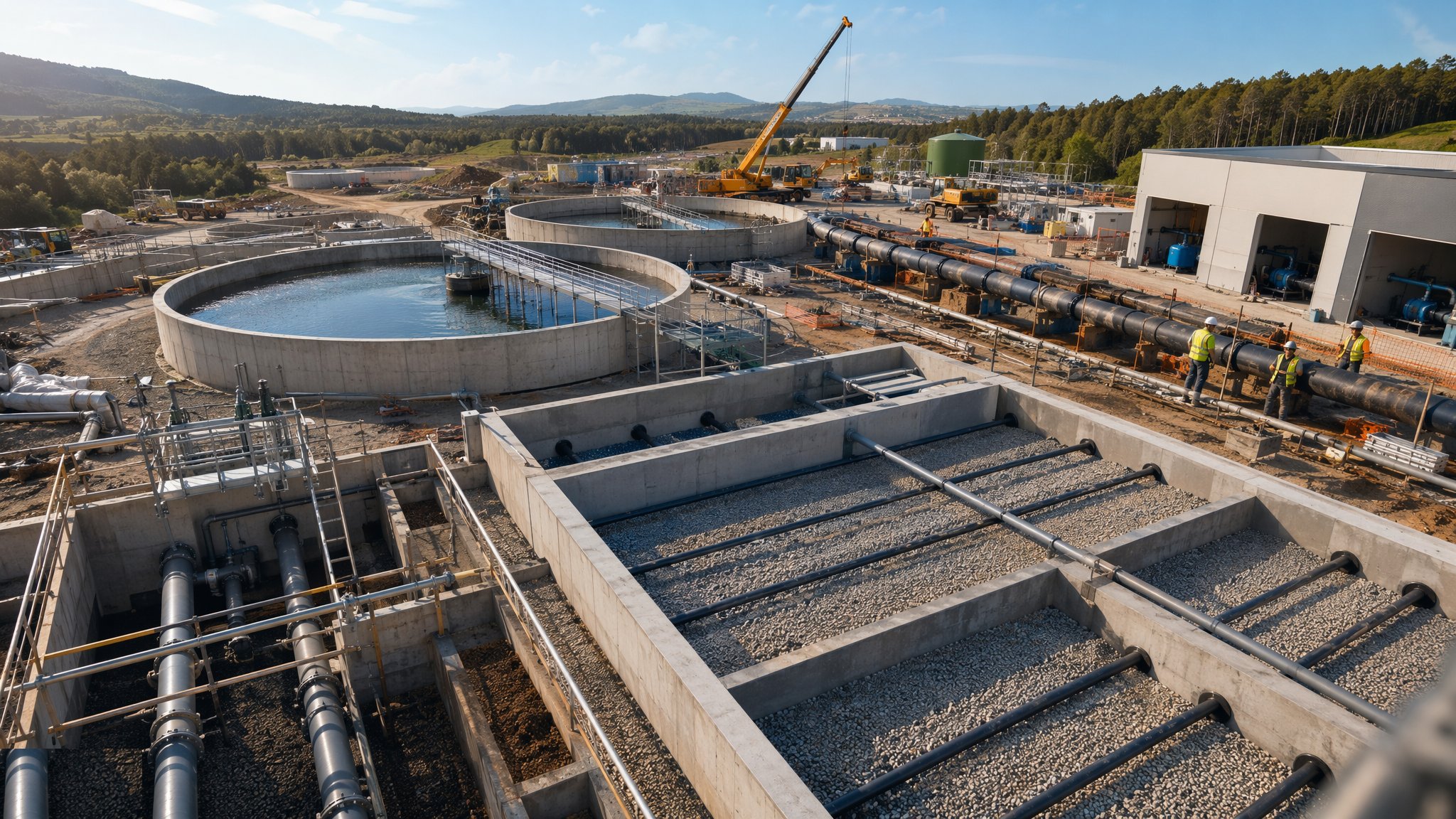
A water treatment works is a chemical plant built out of concrete. Raw water comes in and moves through a chain of process tanks — inlet works and screens, clarification by dissolved air flotation or sludge-blanket clarifiers, rapid gravity filters or membrane cells, disinfection contact tanks, and the clear water tank that feeds supply — and every one of those tanks is a water-retaining structure designed to BS 8007 and EN 1992-3, where the concrete itself is the waterproofing and the design is a controlled argument against cracking: crack widths limited to 0.2 mm by reinforcement and pour sequence, waterstops at every joint, and covers and durability matched to a structure that will hold chlorinated water for sixty years. Everything that touches the water — concrete, coatings, gaskets, pipe materials — must be approved for drinking water contact, in the UK under Regulation 31 of the Water Supply (Water Quality) Regulations, and the paperwork proving it is part of the structure, not an annex to it.
Between the tanks runs the works' circulatory system: process pipework in ductile iron, stainless steel and GRP, with penstocks, sluice gates and actuated valves controlling flow between stages, weirs and launders levelling flow across filters, and the air scour and backwash systems that clean the filter media on their daily cycle. Below the process line sits the recovery side — washwater recovery tanks, sludge thickening and dewatering — because a works that dumps its backwash is a works without a discharge consent. The filter floors themselves are precision work: underdrain systems and nozzle floors set to millimetre level tolerances, because a filter floor out of level backwashes unevenly, and an uneven backwash is media loss, mud-balling and a process engineer writing memos.
The test that disciplines everything is the water-tightness test to BS 8007: the tank is filled, left for the absorption period, then the water level drop is measured over seven days against the allowable — a fraction of the average depth, corrected for evaporation and rainfall. It is a test with nowhere to hide: a leaking kicker joint, a badly fitted waterstop, a honeycombed wall pour all announce themselves in millimetres of lost water. Only when the tanks hold, the valves stroke, and the process chain is proven with water does a treatment works stop being a construction site and become a water company asset — and the quality of the civil work decides how much of the next sixty years is operation and how much is leak-hunting.
When and why is Water Treatment Works Construction used?
Treatment works construction runs on new works, on capacity extensions to existing ones, and on the quality-driven upgrade programmes that add treatment stages — new filters, GAC contactors, UV and ozone plants — to meet tightening standards. It matters because the works is the water company's licence to supply: a tank that fails its tightness test delays the whole commissioning chain behind it, a filter floor out of tolerance undermines the process it was built to serve, and a materials substitution that breaks Regulation 31 compliance can condemn a finished structure to demolition or lining. The civil contractor's margin is in repetition done precisely — bays, walls and kickers cast the same right way forty times — and the penalty for sloppiness is measured in injected joints, emptied tanks and a commissioning programme that will not start.
Types of Water Treatment Works Construction
Rapid gravity filter blocks
Rows of open filter cells with underdrain nozzle floors, media beds, and backwash air and water systems. The workhorse of conventional treatment: repetitive concrete boxes where level tolerance on the floor is the whole game.
Dissolved air flotation (DAF) and clarifiers
Flotation tanks and sludge-blanket or lamella clarifiers removing solids before filtration, with scrapers, launders and recycle systems. Precision weir levels and hydraulics wrapped in water-retaining concrete.
Contact tanks and clear water tanks
Baffled tanks giving disinfectant its contact time, and the covered storage feeding supply. Deep, often partially buried, and always tightness-tested — the works' final word before the water leaves.
GAC contactors and advanced treatment cells
Granular activated carbon beds, membrane halls and ozone or UV contact structures added for quality upgrades. Newer process shapes, same rules: water-retaining concrete, approved materials, tested tight.
Washwater and sludge treatment
Recovery tanks, thickeners and dewatering buildings handling the works' own waste stream. The unglamorous half of the site that the discharge consent makes compulsory.
Water Treatment Works Construction: step by step
Step 1: Prepare the formation and found the tanks
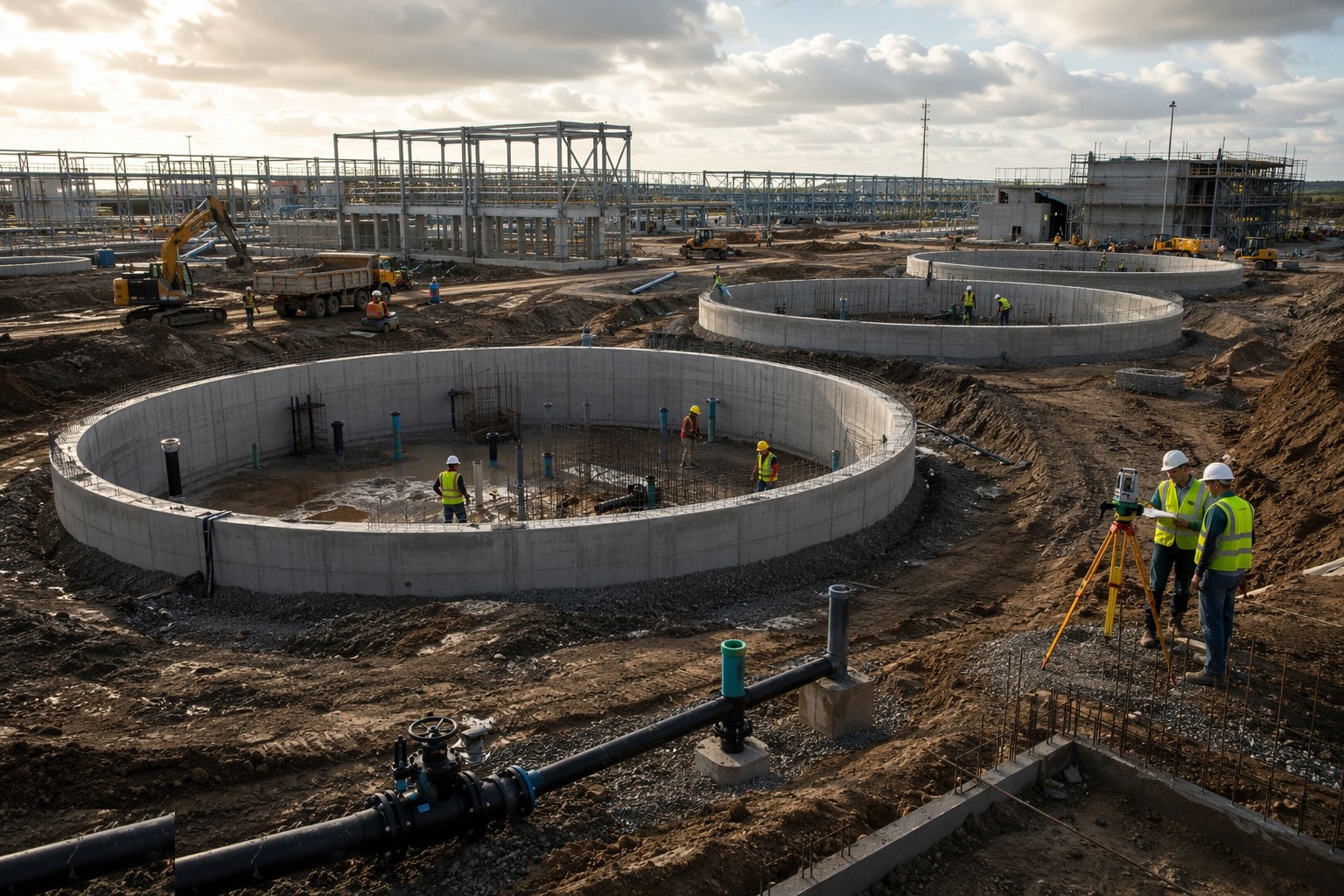
Process tanks are founded on proven ground or on piles where the site demands it, with the formation trimmed, blinded and surveyed to a level tolerance that the thin base slab will not forgive. Drainage and groundwater control run through construction — an empty tank is a boat, and flotation checks govern how far the structure can stand empty against a rising water table. The setting out is done once and checked often: a filter block out of square is a pipework problem inherited by everyone downstream.
Step 2: Cast the water-retaining base slabs
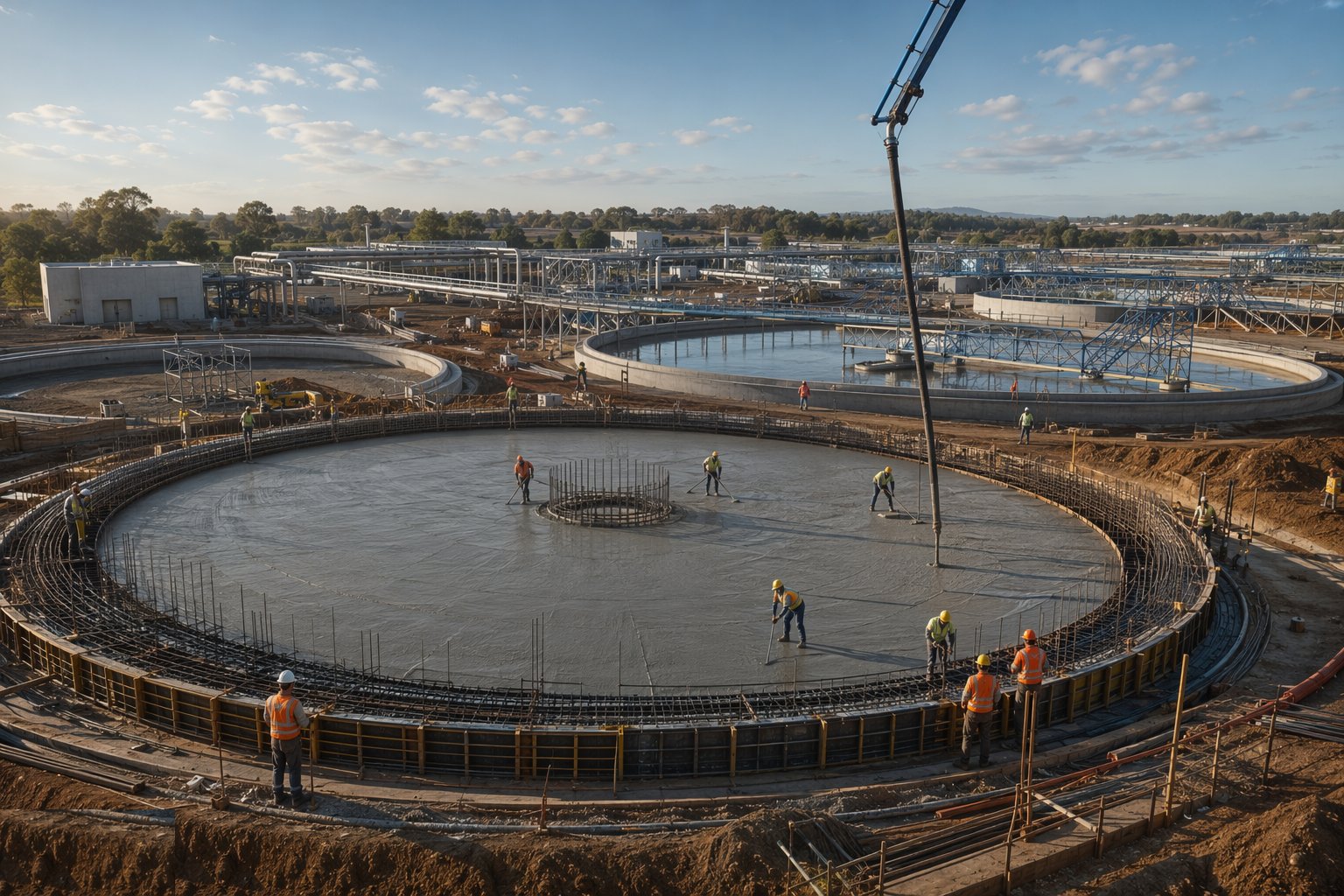
Base slabs are cast in sequenced bays sized to control early thermal and shrinkage cracking, with reinforcement fixed to the BS 8007 crack-width design, waterstops set at every planned joint, and kickers formed as part of the base pour — cast monolithically, not added later. Concrete is placed, compacted and cured like the waterproofing it is: no retempering, continuous vibration without segregation, and curing that starts before the surface can think about drying. Every pour is logged with its cubes, its temperature and its joint preparation for the next.
Step 3: Raise the walls with joints that will hold
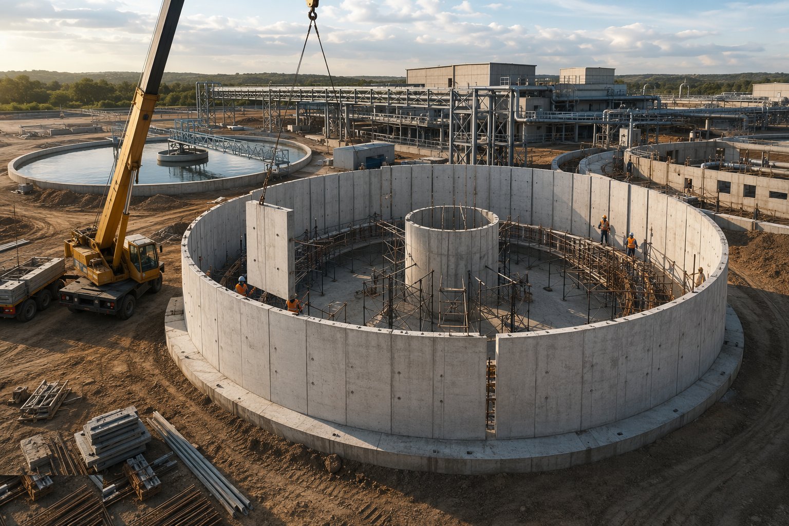
Walls go up in panels matched to the design's movement and crack-control strategy, each pour keyed to the last through prepared joints with waterstops inspected and signed before shutters close. Congested reinforcement at corners, penstock openings and pipe penetrations is where honeycombing is born, so poker access and pour heights are planned, not hoped for. Penetrations are cast in with puddle flanges — the day the tank is tested is far too late to discover a core-drilled shortcut.
Step 4: Build the filter floors, weirs and process details
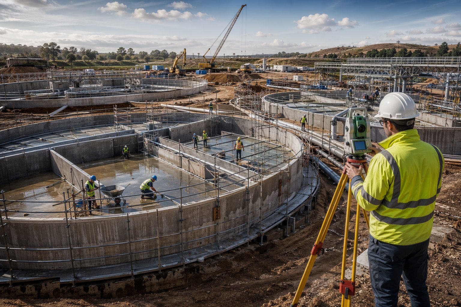
Filter underdrain slabs and nozzle floors are set to their tight level tolerances by survey, nozzles installed to pattern and density, and launders and weirs cast or fixed to levels the hydraulics demand — a weir out of level short-circuits the tank it serves. Channels, sumps and scraper mechanisms follow, each checked against the process contractor's interface drawings, because the civil works exists to serve equipment that has opinions about millimetres.
Step 5: Install the process pipework and valves
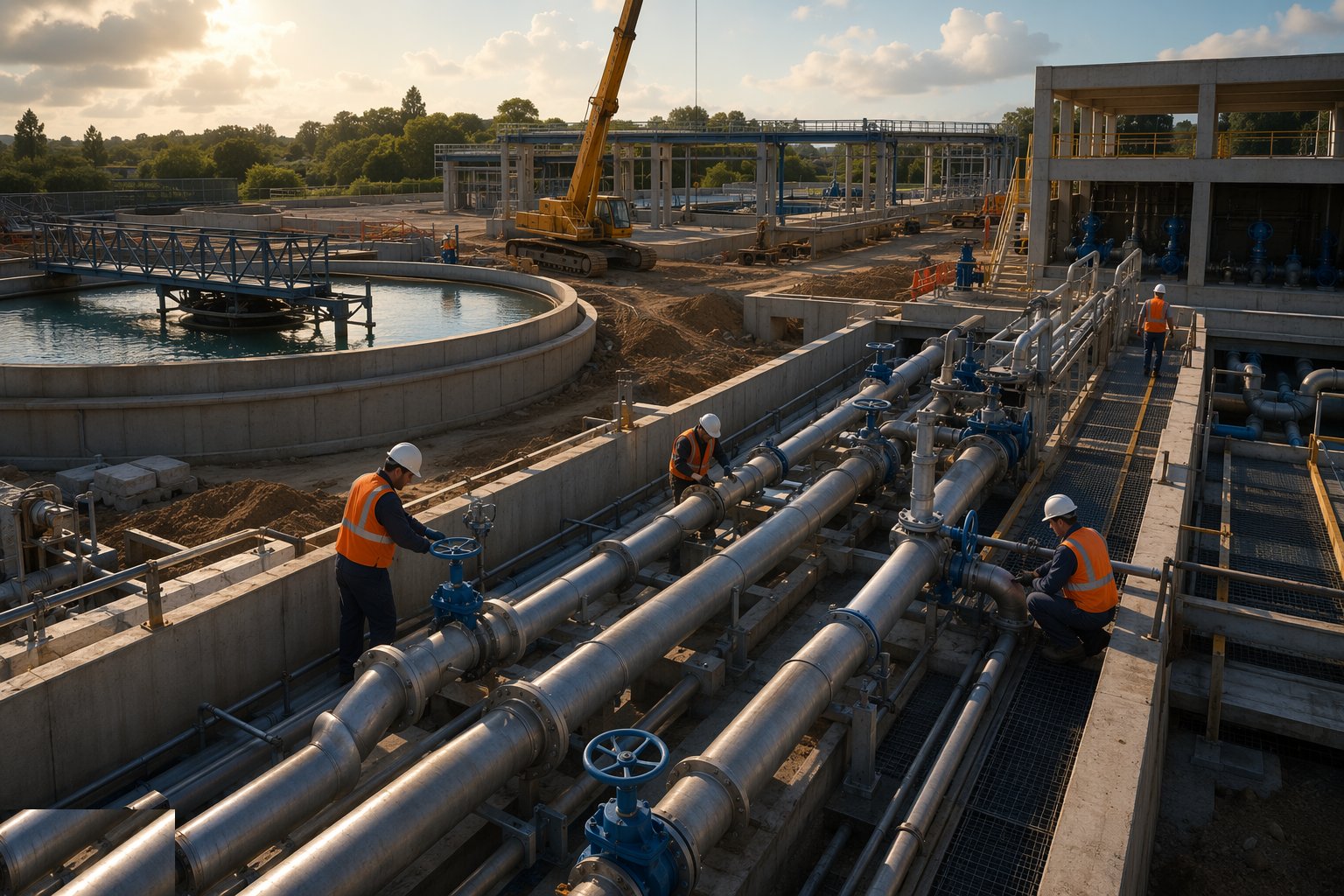
Pipework in ductile iron, stainless steel and GRP is run between tanks and valve chambers on its supports and thrust restraints, joints made and tested per material, and penstocks, sluice gates and actuated valves set plumb, sealed and stroked through their travel. Valve chambers and culverts are built as water-retaining structures in their own right, and every flange, gasket and coating on the water side carries its Regulation 31 approval with the certificates filed.
Step 6: Run the water-tightness tests
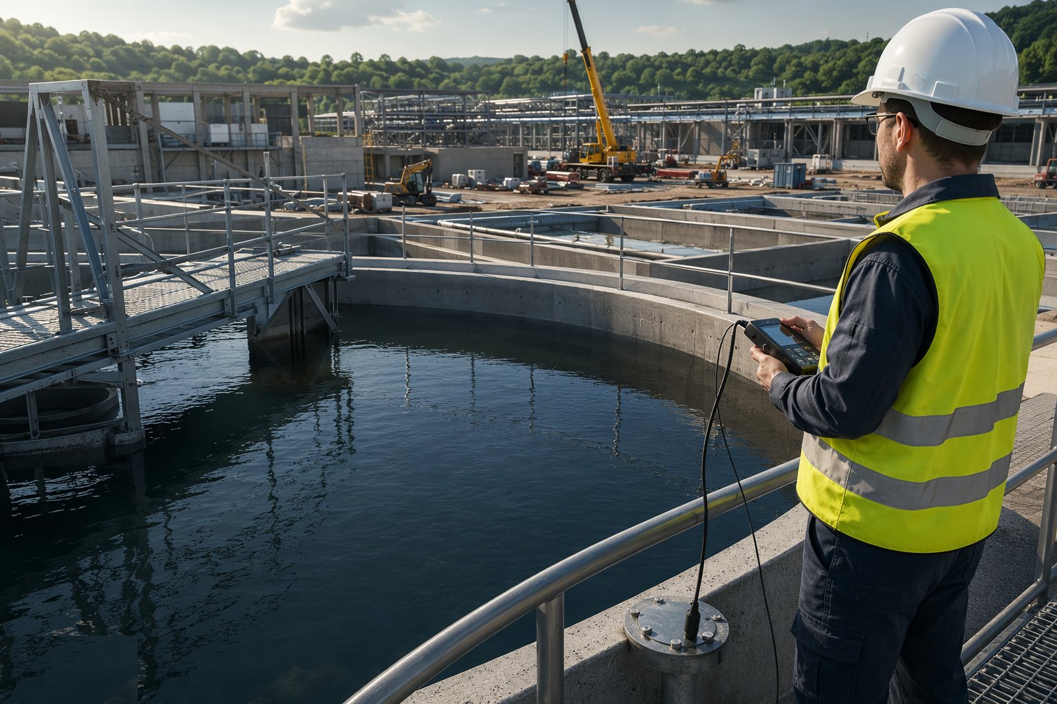
Each tank is cleaned, filled and left for its absorption period, then the seven-day test measures the level drop against the BS 8007 criterion with evaporation and rainfall accounted for. Failures are investigated honestly — joints inspected, suspect pours tested, leaks marked from inside and outside — and repaired by the specified method, then the tank is tested again until it passes. The results are signed and filed tank by tank, because the tightness certificate is the tank's birth certificate and the commissioning programme will not accept a bastard.
Step 7: Commission the process chain and hand over
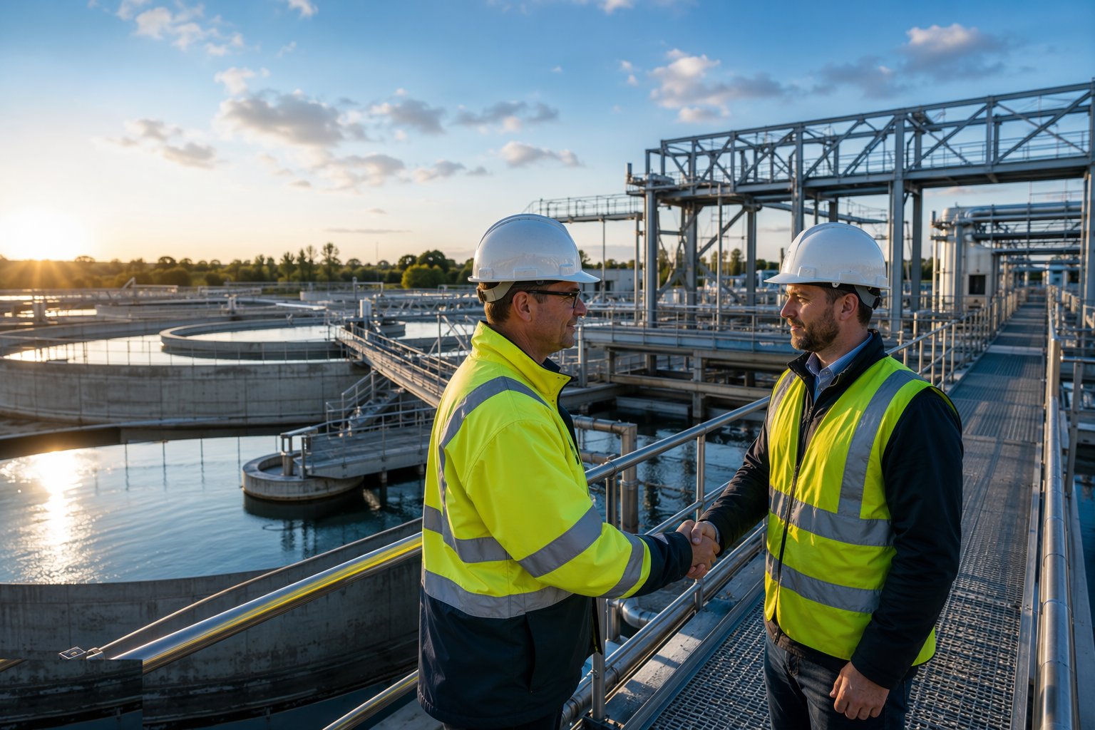
Media is loaded into the proven filter cells, chemical systems are filled and run, and the works is brought on stream stage by stage: clean-water runs first, then process water, with backwash cycles, valve sequences and instrumentation proven under the process engineers' witness. Water quality sampling through commissioning demonstrates the works does what the design promised, the O&M manuals and Regulation 31 file are completed, and the asset is handed to operations. The concrete, if it was loved, is never discussed again.
Plant and equipment
- Tower and mobile cranes serving repetitive tank pours; concrete pumps and placing booms
- Panel formwork systems and falsework designed for tall water-retaining walls
- Waterstop installation kit, joint preparation and inspection equipment
- Dewatering plant and piezometers for below-water-table construction; flotation monitoring
- Survey instruments for filter floor and weir level control — total stations and precise levels
- Pipe installation spreads: fusion equipment for PE/GRP, welding sets for stainless, joint testers
- Test water supply and disposal consents for filling and emptying tanks under test
- Level loggers, evaporation pans and rain gauges for the seven-day tightness tests
Quality control checks
- Concrete records per pour: cubes, slump or flow, temperature, and curing regime against the durability spec
- Cover surveys and crack-width compliance checks against BS 8007 and EN 1992-3 design
- Waterstop and joint inspection sign-offs before every wall pour closes
- Regulation 31 approval certificates for every material in water contact, filed and traceable
- Filter floor and weir level surveys against tolerance before media or equipment loads
- BS 8007 water-tightness test certificates per tank — the gate document for commissioning
Safety considerations
- Deep excavations and below-water-table construction: support, dewatering and flotation risk managed together
- Work above open water as tanks fill: edge protection, buoyancy aids and rescue provision at every open tank
- Confined space entry into tanks and valve chambers: permits, gas testing, ventilation and rescue plans
- Chemical systems arriving during fit-out: chlorine and reagent handling under COMAH-aware procedures
- Repetitive formwork and falsework operations: temporary works control under BS 5975 with a named coordinator
- Lifting over live treatment areas on upgrade works — separation from operating plant agreed and barriered
Common defects
- Kicker and wall-base joint leaks — the classic tightness test failure, repaired by injection at ten times the saving
- Honeycombing at congested corners and penetrations, found when the tank is filled
- Thermal and shrinkage cracks beyond the design width from bays cast too big or cured too late
- Filter floors out of level — uneven backwash, media loss and a process complaint that never dies
- Waterstop displaced or holed during the pour, invisible until the test
- Non-approved substitutions on gaskets or coatings — the paperwork defect that can condemn sound concrete
Best suited for
- New water treatment works and clear water storage on greenfield sites
- Capacity extensions and process upgrades on operating works
- Filter block refurbishments and media replacement programmes
- Washwater recovery and sludge treatment additions driven by consents
How long does Water Treatment Works Construction take?
Typical duration: A medium treatment works is a 24–48-month programme from formation to water; tightness testing adds weeks per tank and sits stubbornly on the critical path, because commissioning will not touch a tank that has not passed..