Service Reservoirs & Water Towers
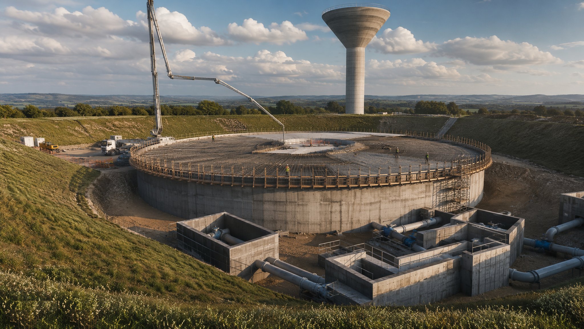
Treated water stored against the day's demand — circular prestressed and rectangular reinforced concrete tanks holding millions of litres, roofs in flat slab, membrane or dome, valve houses and instrumentation at the rim, then cleaning, sterilisation and sampling before the water company lets a drop near the network.
Last updated 2026-07-28 by the BuildPedia Editorial Team.
What is Service Reservoirs & Water Towers?
A service reservoir is the water network's savings account: treated water stored at the right elevation to even out the day's demand and keep pressure in the pipes when the pumps falter. The structures come in families. Circular tanks, often prestressed — post-tensioned walls wrapped or tanked against the outward pressure of the stored water — make the most efficient use of concrete and are the classic big-storage answer. Rectangular reinforced concrete tanks, designed to BS 8007 and EN 1992-3 with crack widths controlled at 0.2 mm, suit awkward sites and compartmented layouts, and compartmentation is itself a design principle: two or more cells so one can be drained, inspected and cleaned while the other keeps the town supplied. Elevated water towers put the storage on a shaft or columns to buy hydraulic head where the ground will not.
The roof earns more engineering than its appearance suggests. Flat slab roofs on columns carry the soil and grass of a buried reservoir and must be waterproofed and drained so that neither rainwater nor a leaking joint finds the stored water; membrane roofs add a continuous waterproofing layer with protection above it; dome and shell roofs span column-free where the geometry suits. Light is the enemy inside — algae grows where daylight leaks in — so every roof joint, hatch and vent is detailed to keep the stored water in darkness while keeping insects and vermin out with it. Around the rim sit the valve house and the instrumentation: inlet and outlet pipework with their isolating and control valves, level instrumentation feeding telemetry, the overflow and washout arrangements, and sampling taps for the water quality regime the asset will live under.
Like every water-retaining structure, the reservoir proves itself in water: the BS 8007 tightness test on each compartment, seven measured days against the allowable loss. But the service reservoir adds a second gate beyond the civil one — cleanliness. Before commissioning, the tank is emptied, cleaned and sterilised: surfaces disinfected by chlorination to the specified dose and contact, then flushed, and bacteriological samples taken and passed before the compartment is accepted into supply. Every material that touched the water carried its Regulation 31 approval; every operative who entered carried water hygiene training; and the record of it all — tightness certificates, sterilisation records, sample results — is what turns fifty million litres of concrete structure into a drinking water asset.
When and why is Service Reservoirs & Water Towers used?
Service reservoirs are built for growth and resilience: new storage for expanding networks, replacement of cracked and leaking Victorian tanks, and security-driven covering and compartmentation of open storage. The structural choice follows hydraulics and ground — circular prestressed where volume and economics align, rectangular where the site or the phasing demands, towers where head must be manufactured. It matters because a service reservoir sits between treatment and the customer with no further barrier: a leak is lost treated water, a roof defect is a contamination route, and a failed commissioning is a public health incident wearing a hard hat. These are structures whose failures make regulators and newspapers at the same speed, so they are built, tested and commissioned with a formality the concrete industry reserves for very few other boxes.
Types of Service Reservoirs & Water Towers
Circular prestressed concrete tanks
Post-tensioned circular walls storing the largest volumes at the least concrete, with strand or wire prestress and protected anchorages. The efficiency answer for big storage — engineered, stressed and tested as a pressure structure.
Rectangular RC compartmented tanks
BS 8007 reinforced concrete tanks divided into cells for operational flexibility, with columns supporting flat slab roofs. The adaptable workhorse: any shape the site allows, one cell always available for cleaning.
Buried and earth-banked reservoirs
Tanks built into or covered by ground, roofs soiled and grassed, invisible from the road. Storage that hides: waterproofed, vented and drained against the ground that leans on it.
Elevated water towers
Tanks carried on shafts or column frames, buying hydraulic head above flat country. Structure, hydraulics and civic silhouette in one — the reservoir as landmark.
Membrane and dome roofed tanks
Continuous waterproof membranes on flat roofs, or shell and dome roofs spanning column-free. The roof as the contamination barrier — chosen, tested and detailed like the asset's first line of defence.
Service Reservoirs & Water Towers: step by step
Step 1: Found the tank and control the ground water
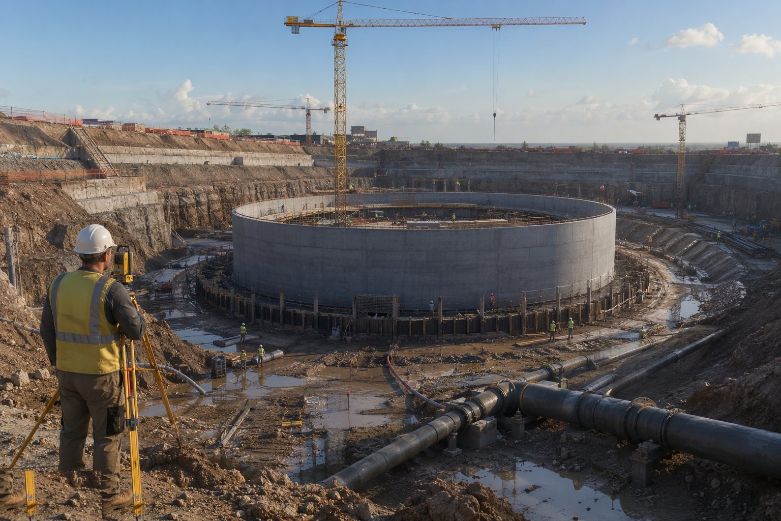
The reservoir is founded on proven ground or piles, with blinding, formation survey and the drainage that keeps construction dry — and the flotation check governs from day one, because an empty reservoir beside a rising water table is buoyancy arithmetic waiting to happen. Compartment layouts, pipework positions and the valve house footprint are set out together, since the inlet, outlet, overflow and washout all land at fixed levels tied to the network's hydraulics, and a pipe cast at the wrong invert is a redesign wearing wellies.
Step 2: Cast the base and raise the walls
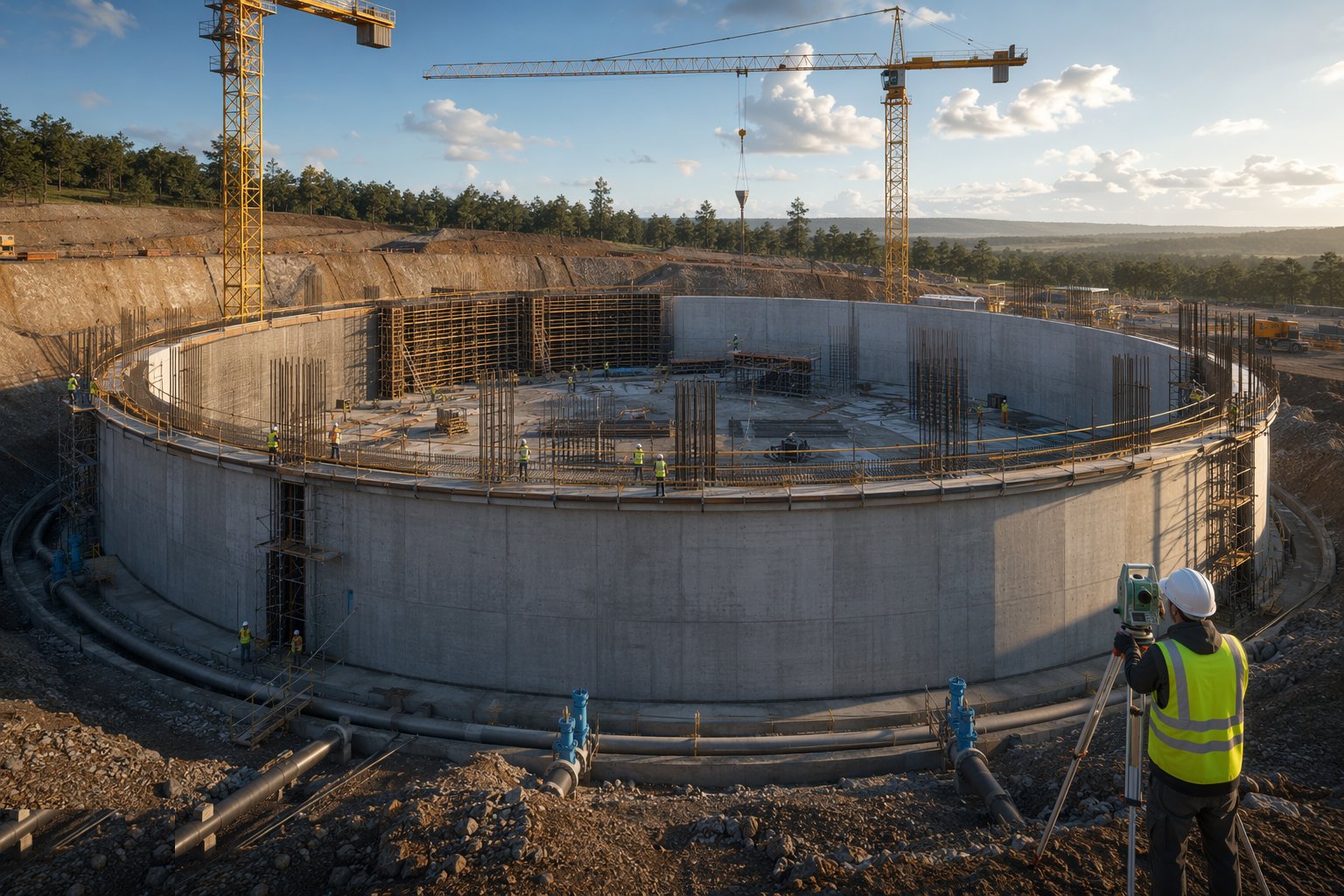
Base slabs are cast in sequenced bays with waterstops at every joint and kickers monolithic with the slab; walls rise in panels to the crack-control design, with wall-base joints — the traditional leak seat — prepared, waterstopped and inspected like the reputation they carry. Circular prestressed walls are stressed in sequence with duct, anchor and elongation records for every tendon. Penetrations are cast in with puddle flanges and the pipework sleeve positions proven by survey before the pour, not after the test.
Step 3: Build the roof and seal it against the world
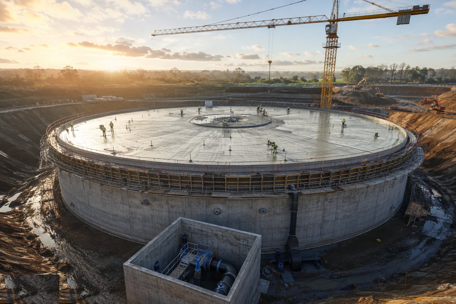
Columns and roof slabs are cast with the falls and drainage the waterproofing needs, or dome formwork erected for the shell. Membranes are laid with every seam tested — electronic leak detection where specified — and protection layers placed before soil or ballast follows. Hatches, vents and access shafts are detailed as contamination barriers: sealed, locked, vermin-proofed and light-tight, because the roof's job for the next sixty years is to let nothing reach the water but the pipework.
Step 4: Fit the valve house and the instrumentation
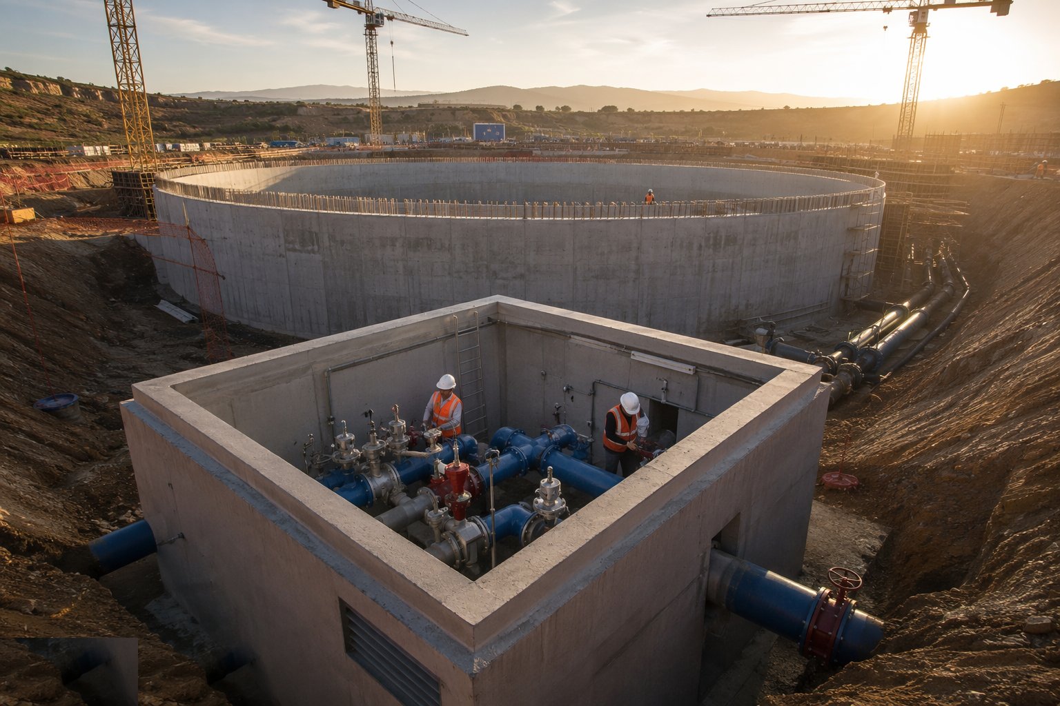
The valve house is built around pipework that arrives through the tank walls: isolating valves, control valves and actuators set, aligned and stroked; the washout and overflow run to their discharge with the consents they need. Level instrumentation, telemetry outstation and sampling taps are installed and wired, with calibration certificates filed. Every valve that will ever isolate a compartment is proven now — a seized valve discovered at the first cleaning outage is a network problem, not a maintenance one.
Step 5: Prove the structure: tightness test by compartment
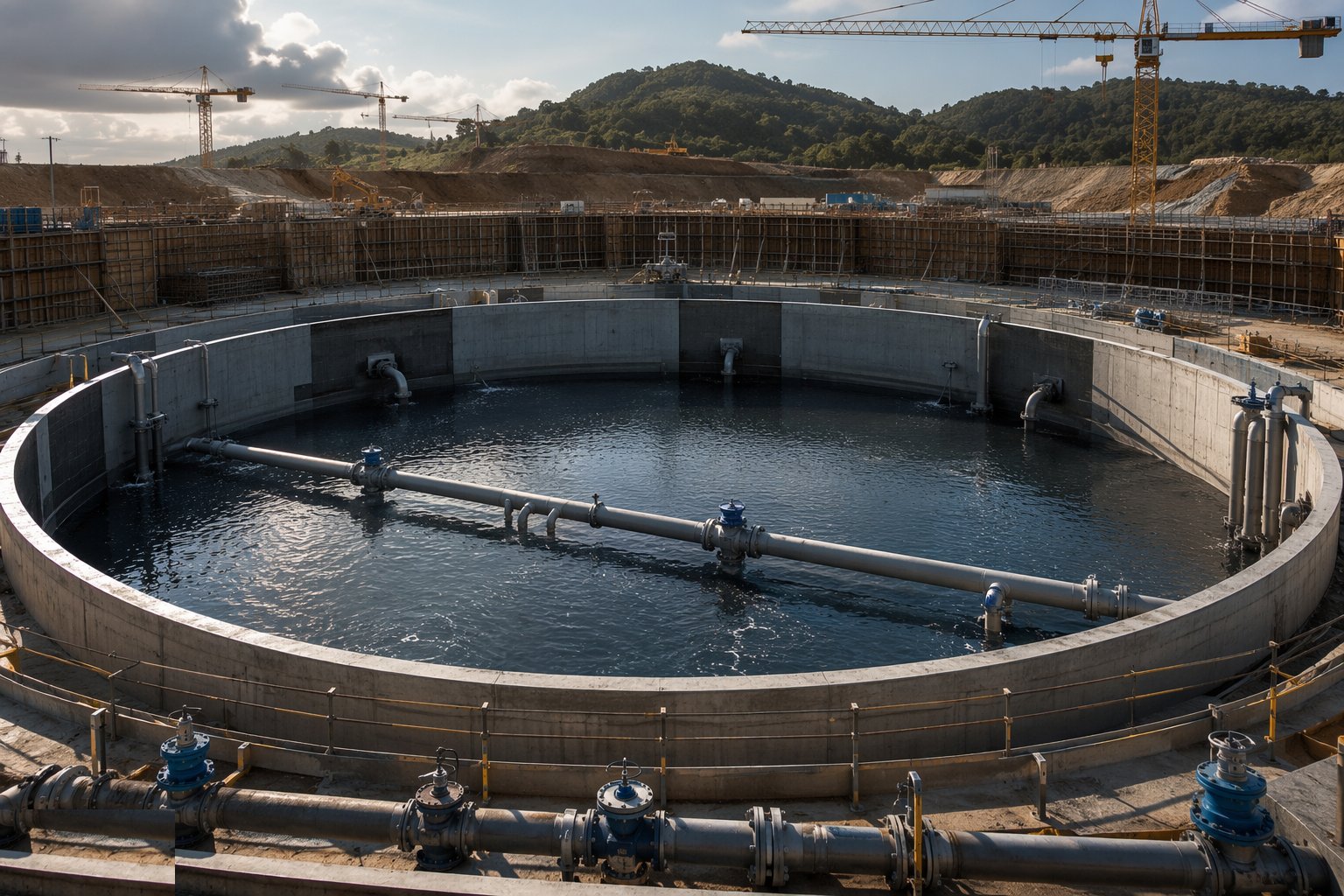
Each compartment is filled, rested through its absorption period, and measured over seven days against the BS 8007 allowable, with evaporation and rainfall accounted. The roof membrane is flood-tested or electronically tested; the pipework and valves are pressure tested with the tank. Failures are investigated and repaired by the specified methods and the test repeated — a reservoir that passes on the third attempt passes exactly once, on the record that matters.
Step 6: Clean, sterilise and sample
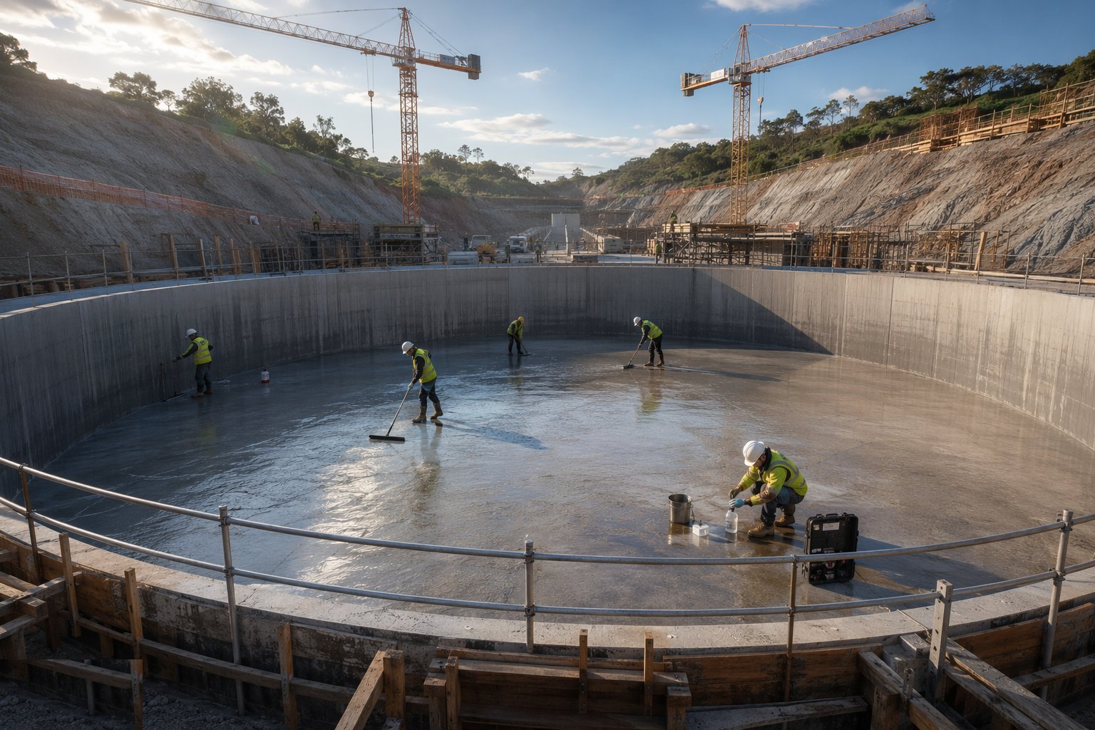
With the structure proven, the commissioning hygiene begins: the compartment is cleaned of every trace of construction, sterilised by chlorination to the specified dose and contact time under the water company's supervision, flushed through the consented discharge, and sampled for bacteriological clearance. Operatives entering work under water hygiene discipline with their training current; every material in contact has its Regulation 31 certificate already filed. The compartment is accepted into supply only when the samples pass — the water company's laboratory, not the site agent, makes that call.
Step 7: Commission into the network and hand over
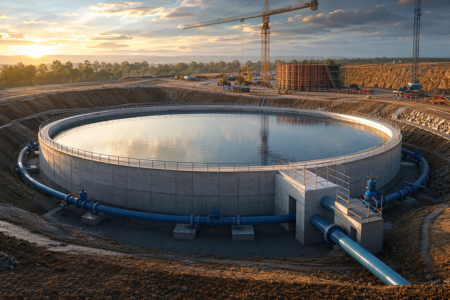
The compartment is brought on line in stages: inlet opened, levels tracked against telemetry, outlet feeding the network under the operations team's control, and the overflow and washout proven. The handover file assembles the whole biography — design, pour records, prestress records, tightness and membrane tests, Regulation 31 file, sterilisation and sample certificates, valve and instrument schedules — and the inspection and cleaning regime is written into the O&M. Then the reservoir does what it was built for: nothing visible, every day, for decades.
Plant and equipment
- Tower cranes and concrete pumps for large repetitive tank pours
- Circular formwork systems and prestressing equipment — stressing jacks, duct and anchorage gear
- Roof formwork and falsework, or dome formwork for shell roofs
- Membrane installation and seam testing kit; electronic leak detection equipment
- Dewatering plant and piezometers; flotation monitoring during construction
- Valve and actuator installation spreads; instrument calibration equipment
- Chlorination dosing, mixing and dechlorination equipment for sterilisation
- Confined space entry and rescue equipment for tank internals
Quality control checks
- Pour-by-pour concrete records and cover surveys against the BS 8007 / EN 1992-3 design
- Prestress records: duct installation, stressing sequence, elongations and grouting
- Waterstop and joint sign-offs before every pour; wall-base joint inspection records
- Roof membrane seam and integrity testing, including electronic leak detection where specified
- BS 8007 tightness test certificates per compartment; pipework and valve pressure test records
- Sterilisation records, bacteriological sample results and the Regulation 31 materials file
Safety considerations
- Flotation and groundwater risk around the empty tank: monitoring and pumping maintained until backfill and ballast are complete
- Work at height on roofs and domes: edge protection and access that survives the membrane's presence
- Confined space entry for internal works and cleaning: permits, ventilation, gas testing and rescue on standby
- Open water as compartments fill: barriers, buoyancy aids and controlled access to tank rims
- Chlorine handling at sterilisation: dosing by trained crews with emergency procedures briefed
- Prestressing operations: exclusion zones at anchorages during stressing and grouting
Common defects
- Wall-base joint leaks — the reservoir's oldest enemy, waiting at the kicker with a syringe repair bill
- Roof leaks at penetrations and seams, found by the flood test or the first winter
- Daylight and insect ingress at hatches and vents — algae and contamination routes in a drinking water store
- Column or floor cracking from settlement between compartments — the tank arguing with its own ground
- Valves that will not seal at the first isolation — unstroked, misaligned or left with debris in the seat
- Failed commissioning samples from inadequate cleaning — construction dust and boot prints read as bacteria
Best suited for
- New potable water storage for network growth and resilience
- Replacement of life-expired or leaking reservoirs
- Compartmented storage allowing maintenance without loss of supply
- Elevated storage providing hydraulic head on flat networks
- Security-driven covering and upgrading of open storage
How long does Service Reservoirs & Water Towers take?
Typical duration: A 20–50 ML service reservoir is a 12–24-month programme from excavation to commissioning; tightness testing, sterilisation and sampling occupy the final months in sequence, and the water company's laboratory — not the programme — decides when the last gate opens..