Commercial MEP & Vertical Distribution
The arteries of the tower — risers, plant floors, AHUs, rising mains and the BMS backbone — distributing air, water, power and data to every floor before the ceilings close over them.
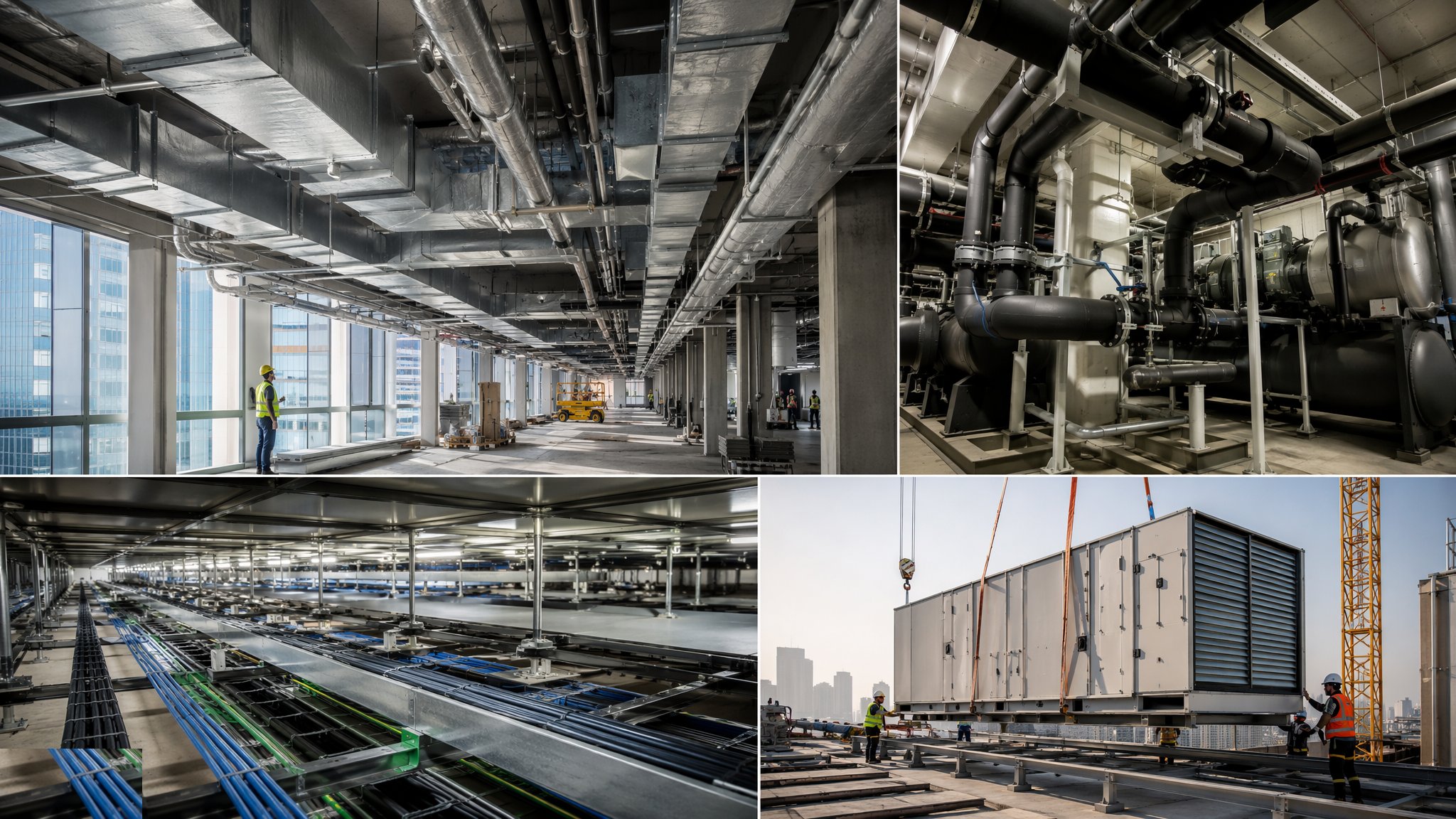
Last updated 2026-07-28 by the BuildPedia Editorial Team.
What is Commercial MEP & Vertical Distribution?
A commercial tower's services are organised vertically. In the core, a stack of riser shafts carries everything that must travel the height of the building: chilled water and heating pipework, ductwork, drainage stacks, electrical rising mains or busbar risers, fire alarm and BMS cabling, and the low-current containment. At the top — or at intermediate plant floors on tall buildings — sit the air handling units, chillers or district cooling connections, pumps, pressurisation sets and main switchgear. On each floor, horizontal distribution branches off the risers into the ceiling void: ductwork and fan coil or VAV terminals, sprinklers, cable containment, small power and lighting. The core's cast-in sleeves and box-outs, planned floors earlier, now either fit the riser schedule or begin an expensive conversation.
The big design fork is how cooling reaches the floor. In the UK the modern office defaults are four-pipe fan coil units fed by central chilled and low-temperature hot water, or VAV systems supplying conditioned air from central AHUs with terminal boxes per zone — with chilled beams on premium low-energy schemes. In the Gulf, district cooling dominates the big commercial districts — chilled water bought by the tonne-hour from Empower, Emicool or Tabreed and fed to the building's energy transfer station — with VRF/VRV direct expansion systems on smaller buildings and as a flexible tenant-level solution. Each architecture has its own installation grammar: water systems are about pipework, flushing, pressure testing and insulation; VAV is about ductwork, leakage testing and controls; VRF is about refrigerant pipework, nitrogen purging, vacuum and charge.
Tying it together is the BMS — the building management system, usually a Tridium Niagara, Trend, Siemens or Schneider backbone with outstations per plant room and floor — which monitors and controls every AHU, pump, valve and meter. The BMS is installed like any other trade during first and second fix, but it only becomes a system during commissioning, and the quality of its installation — containment, terminations, point schedules matched to the reality in the riser — decides whether commissioning is a month of point-to-point checks or a month of archaeology. Electrical distribution runs its own vertical logic: rising mains or busbar risers from the main intake and substation, tap-offs per floor to landlord distribution boards, all installed to BS 7671 in the UK and under DEWA regulations and Civil Defence-listed materials in Dubai.
When and why is Commercial MEP & Vertical Distribution used?
MEP first fix starts as soon as floors are weathertight enough to work and the risers are accessible — which is why the core led the frame: the riser shafts are the first usable vertical space in the building. It runs floor by floor behind the façade and ahead of Cat A, and it must finish ahead of the ceilings because everything it installs is concealed. The order is not arbitrary: risers first because they are the spine and the longest route; plant floors early because AHUs and switchgear are long-lead and commissioning-hungry; floor distribution next, coordinated off the reflected ceiling and services drawings so ducts, pipes, cable tray and sprinklers do not collide in a 450 mm ceiling void. It matters because the concealed services are the fit-out's skeleton — every diffuser, sprinkler head, floor box and lighting row in Cat A and Cat B hangs off what is installed and pressure-tested now — and because a leaking riser joint or an untested busbar discovered after ceilings close costs ten times what it cost to do right.
Types of Commercial MEP & Vertical Distribution
Four-pipe fan coil systems
Chilled and heating water piped from central plant — or a district cooling energy transfer station — to ceiling-mounted fan coil units per zone, each with its own valve set and controls. Flexible, quiet and the UK office workhorse: tenants reconfigure layouts without touching central plant, and the waterside balancing is done at the valves, floor by floor.
VAV with central AHUs
Central air handling units on the roof or plant floors supply conditioned air down ducted risers to variable air volume terminals per zone, which throttle air volume to match load. Excellent fresh air capability and energy performance on deep floor plates — at the cost of big ductwork, rigorous leakage testing and a controls-heavy commissioning burden.
VRF/VRV direct expansion
Refrigerant pipework from outdoor condensers to indoor cassette or ducted units, with branch selector boxes on heat-recovery variants. Fast to install, easily metered per tenant and common on smaller Gulf commercial buildings — but the refrigerant network demands nitrogen-purged brazing, deep vacuum and precise charging, and leak-tightness is everything.
Commercial MEP & Vertical Distribution: step by step
Step 1: Coordinate the risers and confirm the builder's work
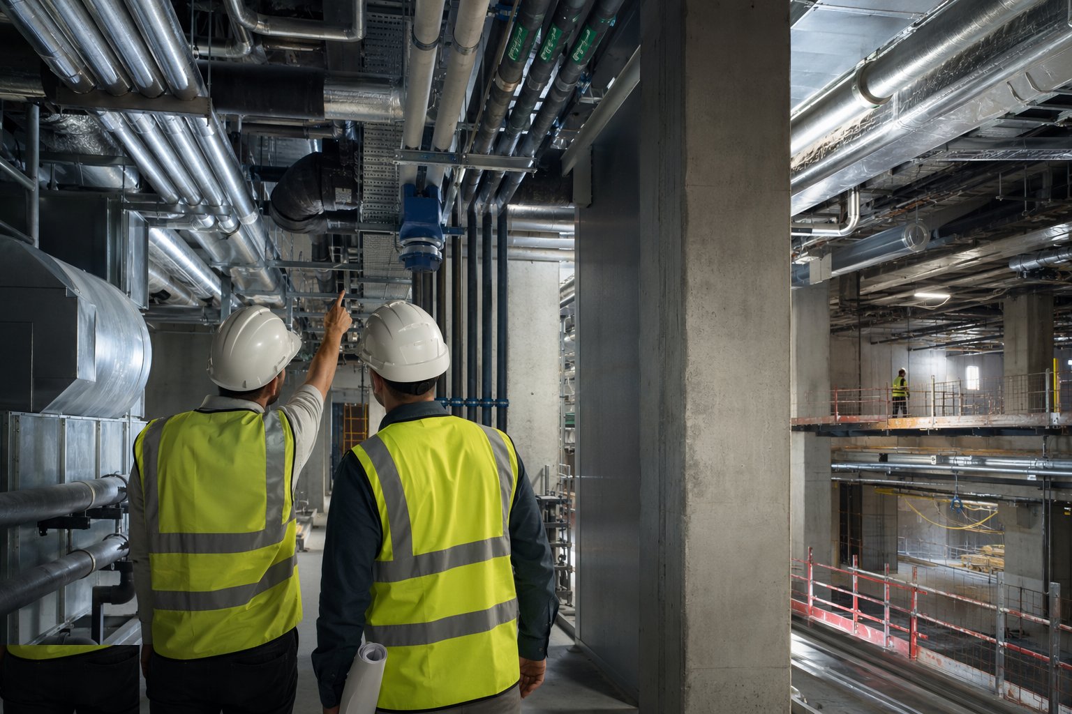
The riser shafts are surveyed against the services drawings: cast-in sleeves and box-outs from the core construction checked for position and size, conflicts raised now while a core drill is still a cheap answer. The riser layout — pipework runs, duct, busbar, containment, valve positions and the access space to maintain them — is coordinated in 3D before a bracket is cut, because a riser that fits on paper and not in the shaft is a redesign at floor 20. Fire strategy is designed in from the start: every penetration through the shaft walls will need its tested fire-stopping detail, and the riser doors and their ratings are part of the compartmentation, not joinery.
Step 2: Install the risers top-down or bottom-up
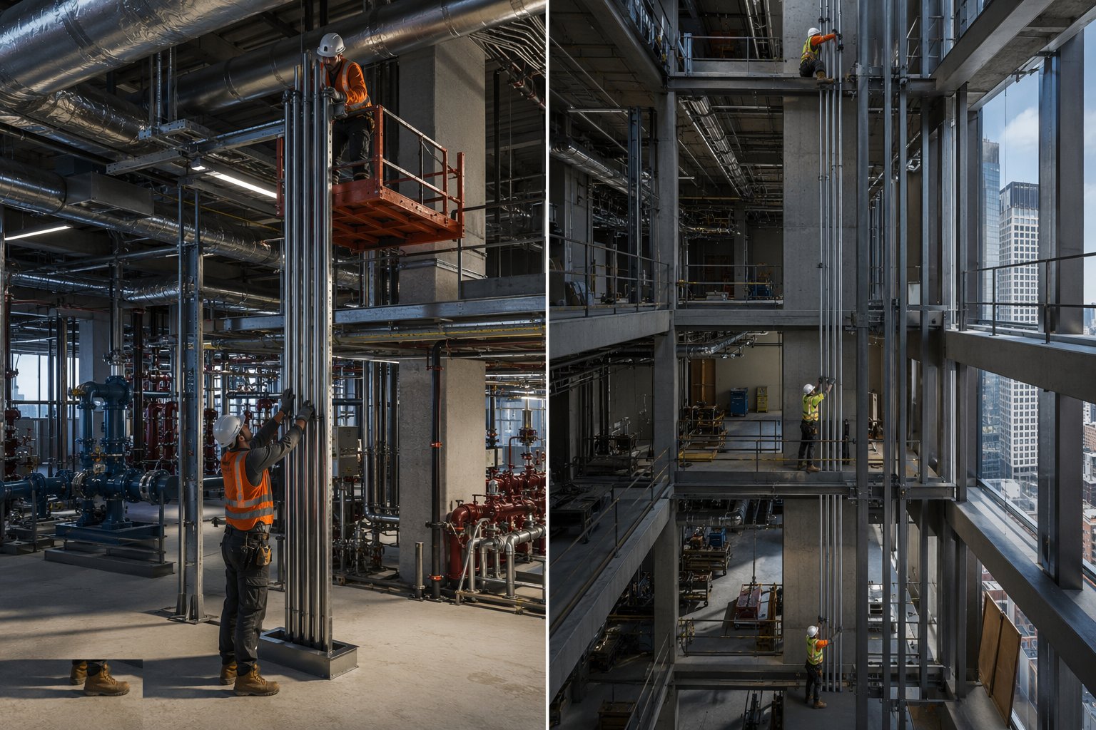
Vertical distribution goes in as complete engineered runs: pipework on hangers and guides with expansion taken at the designed points, ductwork risers section by section, busbar risers or rising main cables fixed and torqued, containment stacked and bonded. Anchor loads into the core walls are per the design — a riser full of water is tonnes hanging off the concrete — and every branch, test point, drain and air vent lands where the commissioning engineer will need it. Each floor's take-off is capped, tested and left ready: the riser is the spine, and it is built once, properly, before the floors make access miserable.
Step 3: Set the plant: AHUs, pumps, switchgear and ETS
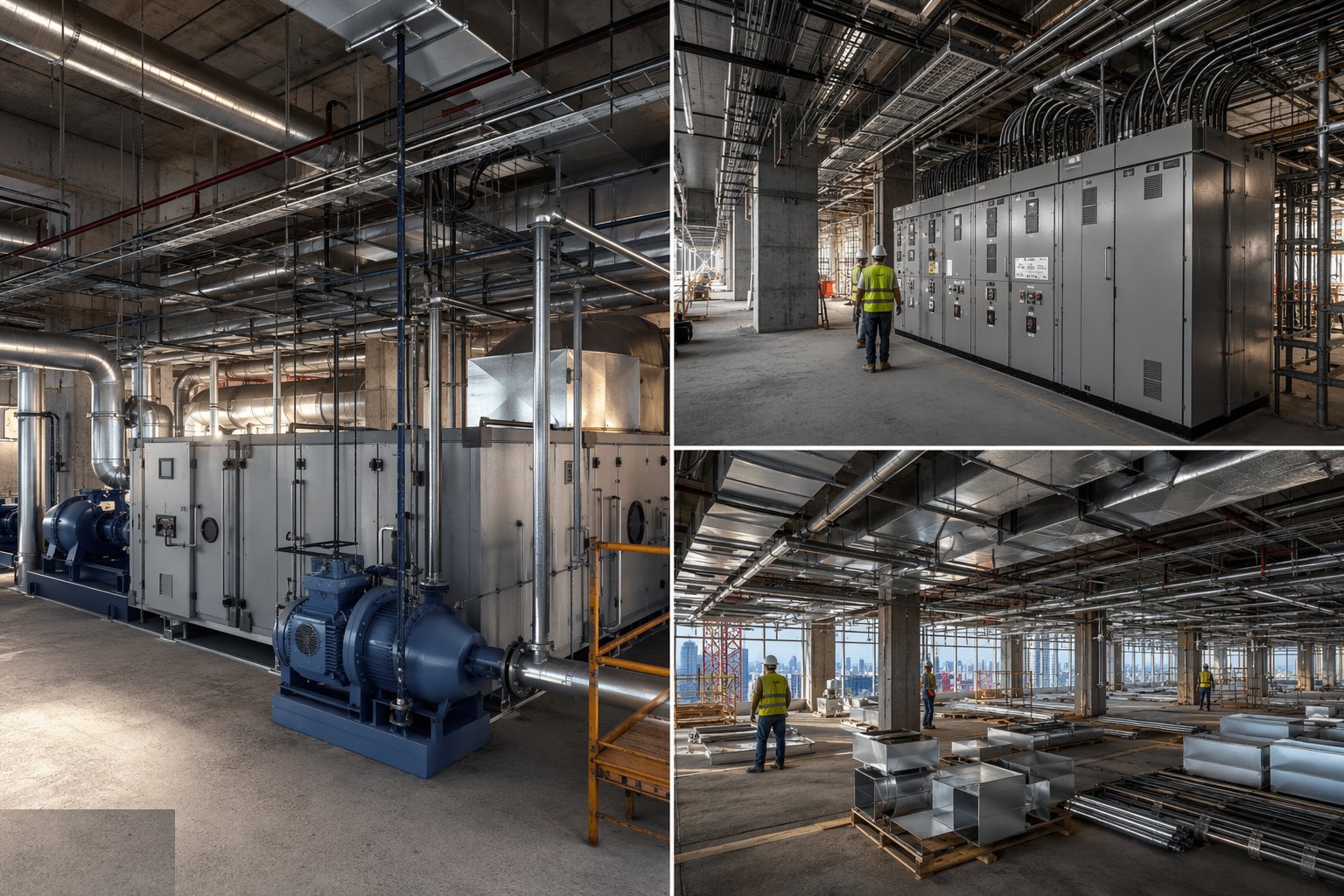
Plant rooms are equipped as early as the structure allows: AHUs landed by crane before the roof closes over them — the lifting study decides whether they go in as units or sections — pumps on their inertia bases, pressurisation and dosing sets, main switchgear and distribution boards, and in Gulf districts the energy transfer station with its heat exchangers and district cooling authority meters. Bases, plinths and builder's work are checked before plant lands; alignment, grouting and pipework flexible connections follow the manufacturers' requirements, because vibration from a badly set pump travels the whole riser and arrives in someone's office as a hum nobody can find.
Step 4: Run the floor-by-floor first fix
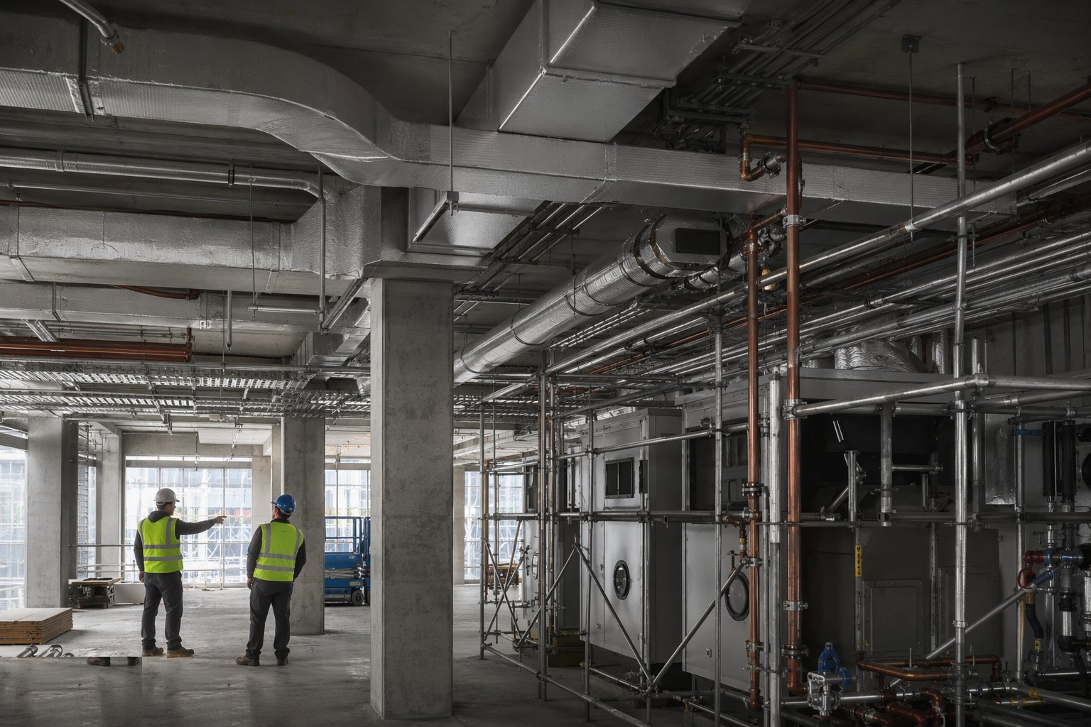
On each floor the horizontal distribution installs against the coordinated services drawings: ductwork on its hangers with the specified leakage class, pipework to fan coils or terminal units with valve sets accessible, sprinkler pipework to the hydraulic layout, cable tray and basket for power and data, and the BMS field wiring to every outstation and sensor point. Heights are held to the ceiling void strategy — services runs clash-checked so the Cat A ceiling grid lands where the letting agent expects it. Penetrations through compartment walls and floors are fire-stopped as they are made, with labelled, photographed records, not patched in a panic before the inspection.
Step 5: Test the concealed systems before they disappear
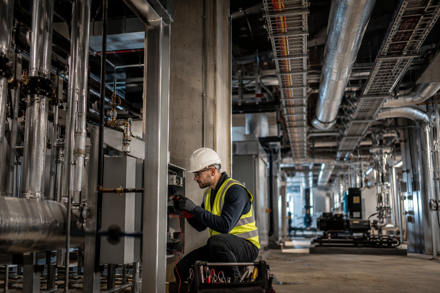
Everything is proven before it is covered: pipework pressure-tested section by section with the results recorded, ductwork leakage-tested to its class under DW/144 practice, rising mains and floor circuits tested to BS 7671 or the local authority's requirements, and sprinkler pipework hydraulically tested to its design standard. Water systems are flushed and chemically cleaned to BSRIA guidance — debris left in a chilled water system is commissioning failure shipped in advance — then filled, dosed and sampled. WIRs or inspection requests close each floor with the consultant before the ceiling programme arrives; the ceiling will not be lifted later for a test certificate nobody got.
Step 6: Install the BMS backbone and pre-commission point-to-point
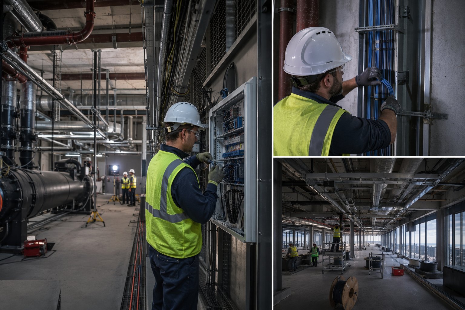
The BMS installs alongside the services: controllers and outstations in the plant rooms and risers, field cabling to valves, dampers, sensors and meters, and the head-end network in the comms room. Before commissioning proper, every point is proven point-to-point — the actuator the graphics say is CHW valve 12 actually stroking CHW valve 12, the sensor reading reality — because a mislabeled point found in cause-and-effect testing undermines the credibility of the whole system. Lifts interface here rather than belong here: the lift contractor runs his own installation and witnessing programme with its independent inspection regime, but his machine rooms, shaft services, fire recall and BMS monitoring points all land in the same risers and the same cause-and-effect matrix.
Plant and equipment
- Tower crane and hoists for landing AHUs, chillers and riser sections
- Pipework fabrication: threading, grooving and welding sets; nitrogen purge and brazing kit for VRF
- Ductwork installation kit: lifters, hangers and leakage test rigs to DW/144
- Pressure test pumps, chart recorders and flushing/chemical cleaning rigs
- Cable pulling winches, busbar jointing and torque tools, electrical test instruments to BS 7671
- Core drills and fire-stopping materials with their tested systems
- BMS field panels, outstations and network infrastructure
- Vacuum pumps, gauges and refrigerant charging equipment for DX systems
Quality control checks
- Riser surveys reconciled to cast-in schedules before installation starts
- Pressure test certificates per pipework section; duct leakage test results per system
- Flushing and chemical cleaning records with water analysis on completion
- Electrical test certificates per floor and riser; busbar joint torque records
- Fire-stopping register: every penetration labelled, photographed and traceable to a tested detail
- BMS point-to-point verification sheets signed before commissioning begins
- WIR/inspection sign-offs per floor before ceilings close
Safety considerations
- Riser work at open shaft edges and voids: edge protection, harness points and controlled access — a riser is a fall route the full height of the building
- Lifting heavy plant onto roofs and plant floors: lifting plans, exclusion zones and weather limits
- Pressure testing: stored-energy procedures, calibrated gauges, exclusion during test and controlled depressurisation
- Hot work on brazing and welding: permits, fire watch and DCD-compliant fire precautions on Gulf sites
- Electrical work on rising mains: safe isolation, authorised persons and energisation only under the authority sequence
- Refrigerant handling on VRF: trained, certificated operatives and ventilation in enclosed plant rooms
Common defects
- Cast-in sleeves misplaced or missing — risers redesigned around core holes that never were
- Pipework pressure-tested as one heroic system rather than section by section — leaks hunted through finished floors
- Flushing skipped or under-dosed — commissioning strainers blocking weekly and fan coil valves eating debris
- Fire-stopping patched late and untraceable — compartmentation failed at the authority inspection
- BMS points mislabeled in the field — cause-and-effect testing becomes a relabeling exercise under programme pressure
- Busbar joints under-torqued — hot joints found by the thermal survey at handover, or later by the smell
- Ductwork over its leakage class — the AHU working forever against air that never reaches the floor
Best suited for
- Vertical distribution in towers where the core risers are the services spine
- Fan coil, VAV or VRF cooling architectures matched to market and floor-plate depth
- District cooling interfaces on Gulf commercial districts
- BMS-driven buildings heading for full commissioning, witness testing and soft landings
How long does Commercial MEP & Vertical Distribution take?
Typical duration: Riser installation typically runs 2–4 months on a mid-rise tower; floor-by-floor first fix follows the façade at roughly one floor per 1–2 weeks per trade, with plant-room fit-out and testing overlapping — allow 8–14 months across the MEP first-fix programme on a 30-storey building..