Long-Span Structural Frames
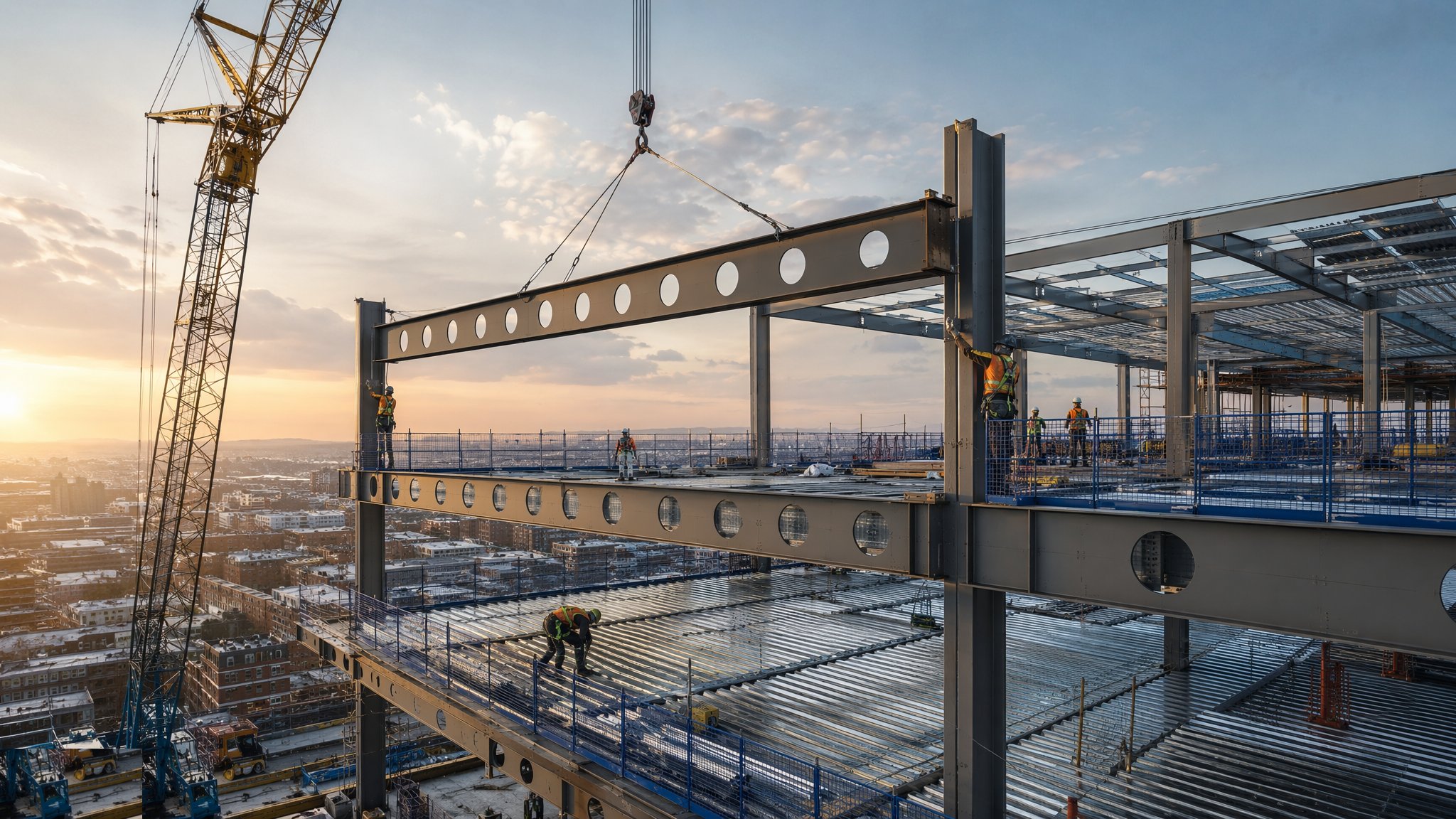
The column-and-beam skeleton that carries the floor plates — steel, concrete or composite — erected around the core and kept plumb, braced and stable as it climbs.
Last updated 2026-07-28 by the BuildPedia Editorial Team.
What is Long-Span Structural Frames?
The frame is what turns a core into a building. Around the core goes the grid: columns on an 8–12 m spacing typical of office planning, beams or slabs spanning between them, carrying every floor plate, façade panel and desk to the foundations. Commercial frames fall into two families. The steel frame — universal columns, cellular or plain universal beams, bolted connections, composite metal deck slabs — dominates UK city offices because it is fast, light and tolerant of long spans. The concrete frame — columns with flat slabs or post-tensioned slabs, or a beam-and-slab frame — dominates Gulf towers, where ready-mixed concrete, cheap formwork labour and thermal mass suit the market, and where the frame often doubles as the fire protection and the acoustic separation for free.
Whatever the material, the engineering of erection is about temporary conditions. A steel frame is not stable until its bracing system — vertical braced bays, shear connections to the core, or the diaphragm of the completed floor — is in place, and the erection method statement works in sequences that keep every bay stable at every stage. In the UK, fabricated steelwork arrives CE/UKCA-marked to BS EN 1090 at Execution Class 2 or 3, erected to the National Structural Steelwork Specification with alignment surveys at each tier. In the Gulf, concrete frames climb behind the core on table forms with back-propping two or three floors deep, and post-tensioned slabs are stressed, grouted and released on a weekly cycle — the frame and the floor plate are the same operation.
The tall-building problem is accumulation. A column a few millimetres out of plumb per storey is a tower leaning by the time the façade designer asks for his fixing tolerances, and a frame erected level on average can still hide individual columns far enough out to break the curtain walling's adjustment range. The frame is surveyed tier by tier — position, plumb, level — against tolerances the façade and core teams have agreed they can live with, because from here on, every trade hangs off the frame's geometry.
When and why is Long-Span Structural Frames used?
Frame erection follows the core up the building, typically a few floors behind, and runs in parallel with the floor plates — on a steel frame the decking follows the steel almost immediately; on a concrete frame the slab is the floor plate. The material choice is made early and on commercial logic: steel where speed, long spans and site congestion argue for dry construction and a small site workforce; concrete where material economics, fire strategy, acoustics and local skills argue for wet construction and a bigger one. It matters because the frame sets the building's rhythm — one floor per week per crane on steel, a weekly pour cycle on concrete — and because its geometry is the reference for the three trades that follow and cannot forgive error: the floors that land on it, the façade that bolts to its edges, and the partitions and risers that repeat its grid forty times over.
Types of Long-Span Structural Frames
Braced steel frame with cellular beams
Universal columns and beams with web openings for services, stability from vertical braced bays or the concrete core, and composite deck slabs. The UK city office standard: fast erection, services threaded through the beams rather than under them, and fire protection by intumescent coating or boarding applied after.
Composite steel-concrete frame
Steel columns and beams acting compositely with the concrete slabs through shear studs — sometimes with slim-floor or integrated beam sections to flatten the construction depth. The efficiency play: less steel, less depth, and the slab working as part of the beam rather than dead weight on it.
Post-tensioned concrete flat-slab frame
Concrete columns with flat slabs — no downstand beams — post-tensioned with bonded or unbonded tendons stressed after the concrete hardens. The Gulf tower default and common on UK residential-over-commercial podia: thin slabs, flat soffits for services and ceilings, and a fast table-form cycle.
Concrete frame with shear walls and core
A conventional column-and-slab reinforced concrete frame relying on the core and shear walls for stability, built to BS EN 13670 execution tolerances with the frame and floor plates cast together. Robust, fire-resistant and quiet — but every floor is a formwork, reinforcement, pour and striking cycle, and the programme runs on concrete strength gain, not crane lifts.
Long-Span Structural Frames: step by step
Step 1: Set out, check and grout the base connections
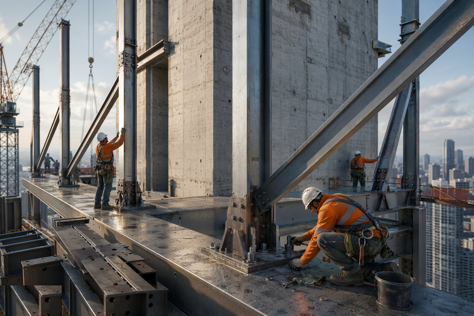
Everything downstream hangs off the first tier. Holding-down bolt groups are surveyed against the grid before columns arrive — cast-in bolts that have wandered beyond the adjustment of the base plates mean drilled-in retrofit anchors and a design query on day one. Columns are landed, levelled on shim or screw jacks, plumbed, and the bases grouted with non-shrink grout once alignment is confirmed — not before, because grout poured to a wrongly set column is a demolition job. On concrete frames, the equivalent discipline is the starter bars and kickers from the core and transfer levels: couplers checked, kickers cast true, and the first lift of columns plumbed against survey control.
Step 2: Erect columns and beams in a stable sequence
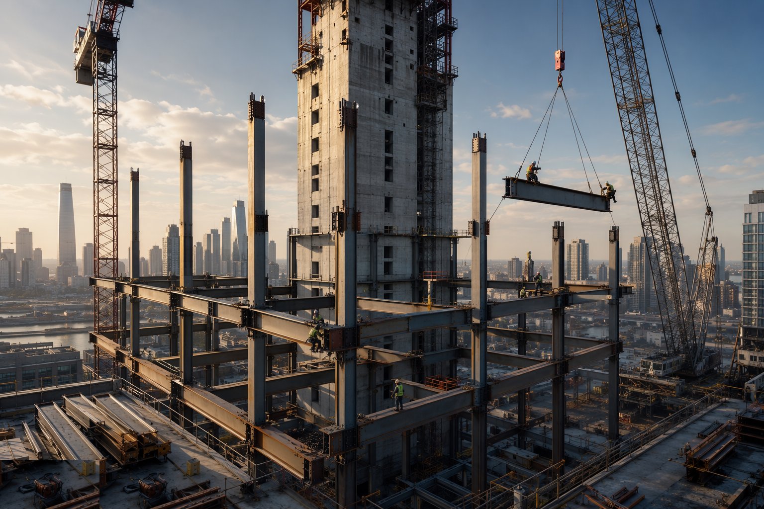
Steel erection follows the method statement bay by bay: columns first, beams connecting them, and the braced bay or core connection completed before the crane wanders off to the next area — an unbraced line of columns is a row of dominoes waiting for a gust or a nudge. Two-bolt minimum rule on connections as members are landed, erection bolts until the permanent bolting follows, and guys, props or temporary bracing wherever the sequence demands. Concrete frames run their own sequence: column forms struck and columns standing before the table forms fly in, edge protection on the slab edge before the deck is a workplace.
Step 3: Complete the connections: bolts and welds
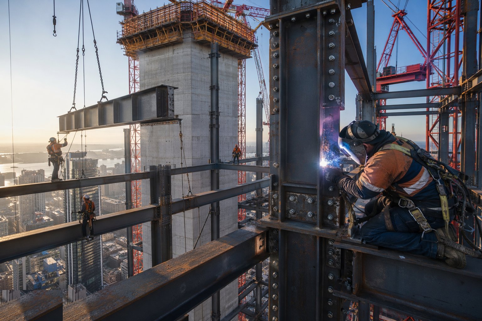
Bolted connections are completed with the specified bolts, tightened by the specified method — pre-loaded HSFG assemblies in slip-critical connections tightened with torque or part-turn methods and verified, bearing-type connections snugged and checked. Untorqued or wrongly assembled pre-loaded bolts are the classic latent frame defect: invisible, load-critical, and found either by the torque audit or by a slipping joint under load. Site welding, where specified, is done by coded welders to approved procedures with the specified level of NDT — in most commercial frames welding stays in the fabrication shop precisely because site welding is slow, expensive and weather-dependent.
Step 4: Survey and correct the alignment, tier by tier
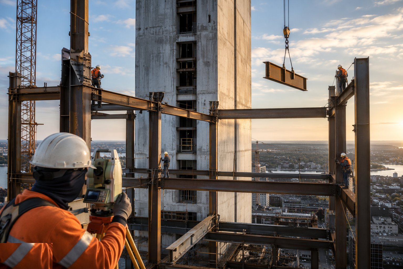
Each tier is surveyed after erection and before the floors lock it in: column plumb and position, beam levels, overall frame geometry against the NSSS or project tolerances and — critically — against what the façade can absorb. Corrections are made by adjustment at the tier above, never by forcing members, and the survey record goes to the decking, slab and façade teams as their working datum. On concrete frames the same check applies to column plumb and slab edge positions; the edge of slab is the curtain waller's fixing line and it is surveyed like one.
Step 5: Integrate temporary stability with the permanent works
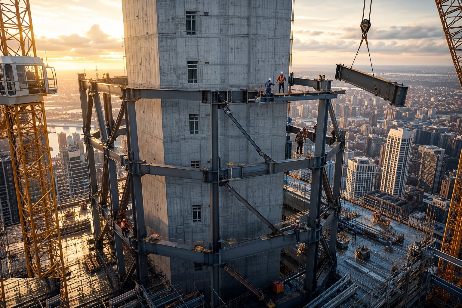
The frame is stable permanently only when the bracing, core connections and floor diaphragms are complete — until then, stability is a temporary works problem with a named owner under BS 5975 and the Temporary Works Coordinator. Erection sequences are planned so that no stage leaves the frame reliant on the crane for stability; decking is spread and fixed promptly because the deck is the diaphragm; and on concrete frames, back-propping between floors is designed, installed and struck to a sequence that respects the loads from wet concrete above — a fresh slab plus its formwork and plant routinely exceeds the design imposed load of the floor carrying it.
Step 6: Apply fire protection and corrosion protection
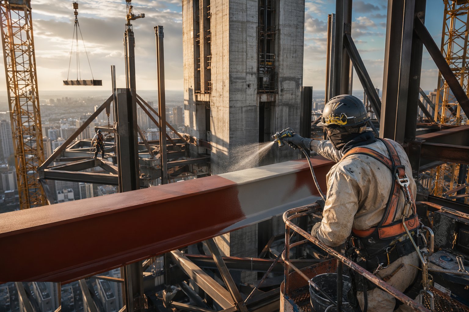
Steel has no inherent fire resistance: the intumescent coating, board or spray that gives the frame its 60, 90 or 120 minutes is applied after erection, to the specified dry film thickness or board thickness, with repairs where erection damage stripped the shop-applied primer or coating. In the UK the specification follows the fire strategy and the coating manufacturer's assessment; in the UAE the fire protection system must be listed and approved under the UAE Fire and Life Safety Code with Civil Defence sign-off. Corrosion protection is inspected with the same discipline — a tower frame near the Gulf coast with damaged galvanising or paint is a maintenance liability cast into the structure.
Plant and equipment
- Tower cranes as the primary erection tool; mobile or crawler cranes for podium and ground-level work
- MEWPs and erection access equipment for connection work at height
- Torque wrenches, part-turn equipment and bolt-tension verification kit for pre-loaded connections
- Total stations, laser levels and GNSS for tier-by-tier alignment surveys
- Welding sets and NDT equipment where site welding is specified
- Table forms, props and back-propping systems for concrete frames
- Post-tensioning jacks, stressing pumps and grouting equipment for PT slabs
- Intumescent and fire-boarding application equipment
Quality control checks
- Fabricated steel certified to BS EN 1090 with CE/UKCA marking and mill certificates traceable to members
- Holding-down bolts surveyed before erection; base grout strength verified before loading
- Bolt installation audits: correct assemblies, tightening method and verification records on pre-loaded connections
- Weld procedure approvals, welder qualifications and NDT records where site welding applies
- Tier-by-tier alignment surveys filed against tolerance — frame geometry issued to dependent trades
- Intumescent dry film thickness tested on a grid; fire protection certification to the fire strategy
- PT stressing records: jack pressures, elongations and grouting logs for every tendon
Safety considerations
- Steel erection at height: MEWP access to connections, fall-arrest only where collective protection is impossible, and edge protection on every floor as it is decked
- Lifting operations under plan: exclusion zones under loads, tagged craneage, and no erection in wind beyond the method statement limits
- Temporary stability owned and inspected — no bay left unbraced overnight, no props or back-props struck without sign-off
- Falling-object protection: tool lanyards, bolt keepers, and barriered zones below erection fronts
- Hot work where site welding occurs: permits, fire watch and extinguishers — doubled down under UAE Fire Code construction-phase rules
- Concrete frame cycles: formwork striking under permit, PT stressing exclusion zones behind anchorages, and controlled access on freshly poured floors
Common defects
- Holding-down bolts cast out of position — base plates slotted, retrofit anchors, and a slow start to the steel programme
- Pre-loaded bolts installed loose, wrongly assembled or with the wrong washers — slip-critical joints that slip
- Bracing omitted or connections left on erection bolts — the frame stable by luck rather than design
- Column plumb drifting tier on tier until the façade fixing tolerance is blown — the most expensive survey conversation on the job
- Intumescent thickness short of specification, or fire protection damaged at connections and never repaired
- Back-props struck early or in the wrong sequence — cracked slabs below the pour and a temporary works NCR
- PT tendons under-stressed, misprofiled or grouted late — deflection and cracking that only show once the floors are loaded
Best suited for
- Long-span office floor plates on an 8–12 m column grid
- Steel frames where dry construction, speed and a small site workforce win
- Concrete and PT frames where material economics, fire strategy and local skills win
- Frames chasing a slipformed or jump-formed core up a tall tower
How long does Long-Span Structural Frames take?
Typical duration: Steel frames typically erect at around one floor per week per crane on a regular grid; concrete frames run a one-to-two-week cycle per floor including propping — a 30-storey frame is a 7–12 month operation from first column to roof..
Related processes
- Core Construction — Slipform & Jumpform
- Floor Plates & Composite Decks
- Curtain Walling & Unitised Façades
- Commercial MEP & Vertical Distribution
- Cat A Fit-Out
- Cat B Fit-Out
- Testing, Commissioning & Handover — Commercial
- Long-Span Structural Frames in Off-Site & Modern Methods
- Commercial & Workplace sector guide
- Buildings group