Propping, Façade Retention and Temporary Support
Holding a building up while you take parts of it away — needle beams, raking shores, façade retention frames and the monitoring that tells you it is all still standing.
Last updated 2026-07-28 by the BuildPedia Editorial Team.
What is Propping, Façade Retention and Temporary Support?
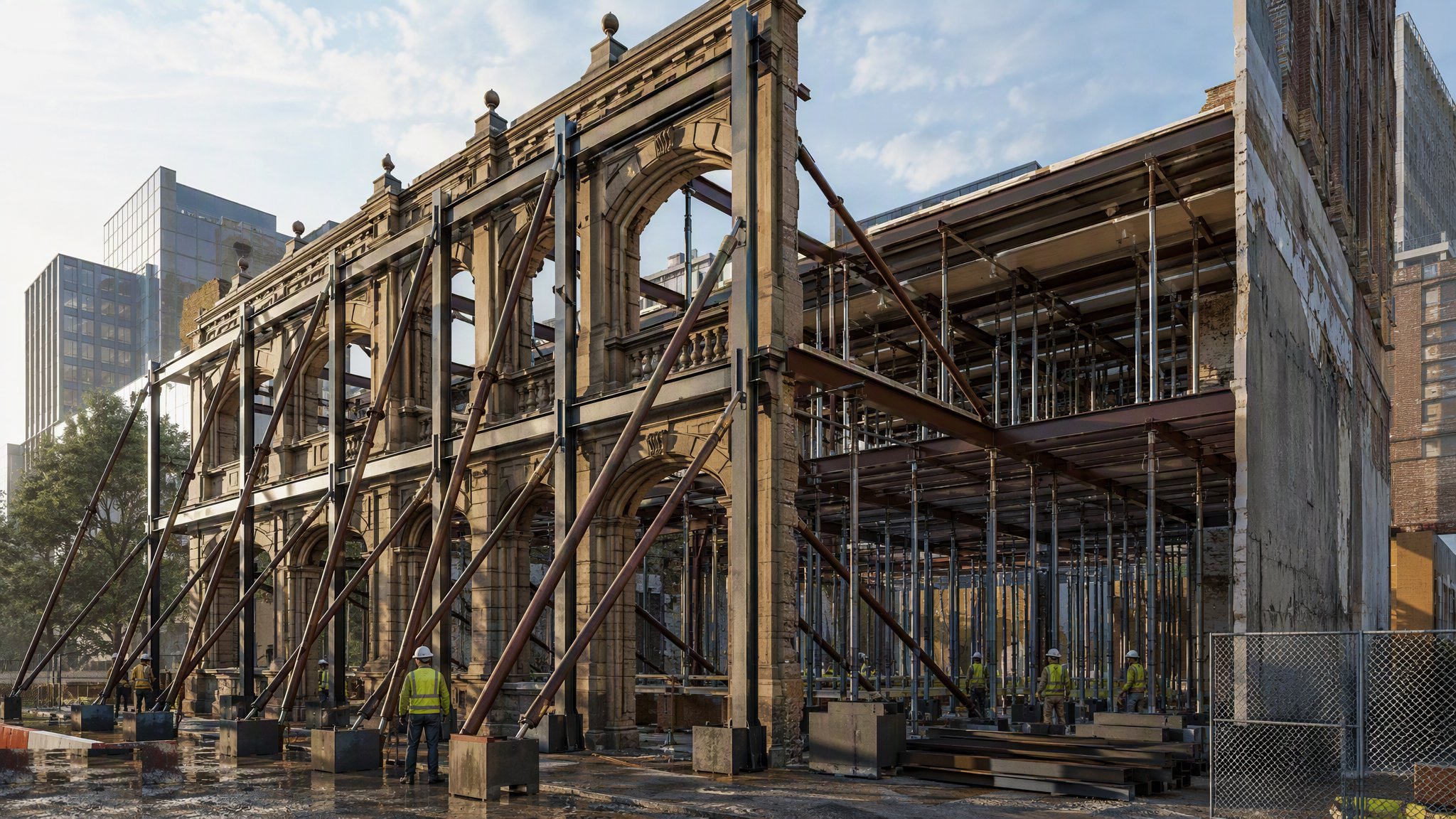
Temporary support is the quiet engineering that makes refurbishment and structural alteration possible. Before a wall comes out, an opening is enlarged or a façade is kept while everything behind it is demolished, something has to carry the load that wall was carrying. That something is usually steel: needle beams threaded through the wall to catch it from both sides, raking shores leaning against a party wall to stop it toppling, flying shores spanning between two buildings, or a full façade retention frame — a steel exoskeleton that holds a listed frontage upright while a brand-new building grows behind it.
The distinction that matters on site is between dead shoring (carrying vertical load), raking shoring (resisting lateral load and overturning) and flying shoring (bracing across a gap). Most real schemes mix all three. Every one of them is designed temporary works under CDM, with a Temporary Works Coordinator, a design check category and an erection sequence — because the moment of maximum risk is not the finished scheme, it is the hour when the wall is cut and the needles are not yet loaded. In the UAE the same logic applies to villa extensions and podium alterations, with DDA or Trakhees approving the temporary works drawings alongside the permanent ones.
Monitoring is not decoration. A retained façade that moves 20 mm at the parapet is telling you something, and the trigger levels in the design — amber at one figure, red at another, with a written action for each — are the difference between a controlled adjustment and a collapse in the street.
When and why is Propping, Façade Retention and Temporary Support used?
Temporary support goes in before any structural removal — it is the enabling works for demolition-behind-façade schemes, basement insertions under occupied buildings, wall removals for extensions and opening enlargements in loadbearing masonry. It is chosen because the alternative is not doing the job: on conservation and listed-building work in the UK the façade is often the planning condition, so retention is the price of consent. The sequencing rule is absolute — support installed, loaded and checked before the structure it replaces is touched, and left in place until the permanent structure has reached the strength to take over, confirmed by test results, not by the programme.
Types of Propping, Façade Retention and Temporary Support
Needle beams and dead shores
Steel needles threaded through pre-cut holes in a wall, carried on props or needle beams each side, so the wall above an opening can be supported while the section below is removed. The classic method for enlarging openings and inserting beams in loadbearing masonry.
Raking shores
Inclined timbers or steel sections from a ground sole plate up to wall plates, holding a bulging, fire-damaged or demolition-adjacent wall against overturning. Seen on party walls when the neighbouring building comes down first.
Flying shores
Horizontal struts spanning between two stable buildings across the gap left by a demolished middle one, bracing the exposed party walls. Designed for the wind and stability loads the demolished building used to resist.
Façade retention frames
A braced steel frame — outside the façade, inside it, or both — that restrains the retained frontage laterally and sometimes vertically while the entire structure behind is demolished and rebuilt. Common on central-London commercial refurbishments and increasingly on Dubai podium refits.
Underpinning support
Temporary needles and props carrying the existing foundation while new mass-concrete or mini-piled underpinning is placed in short, sequenced bays — the support regime is what makes underpinning survivable for the building above.
Propping, Façade Retention and Temporary Support: step by step
Step 1: Survey, investigate and establish the loads
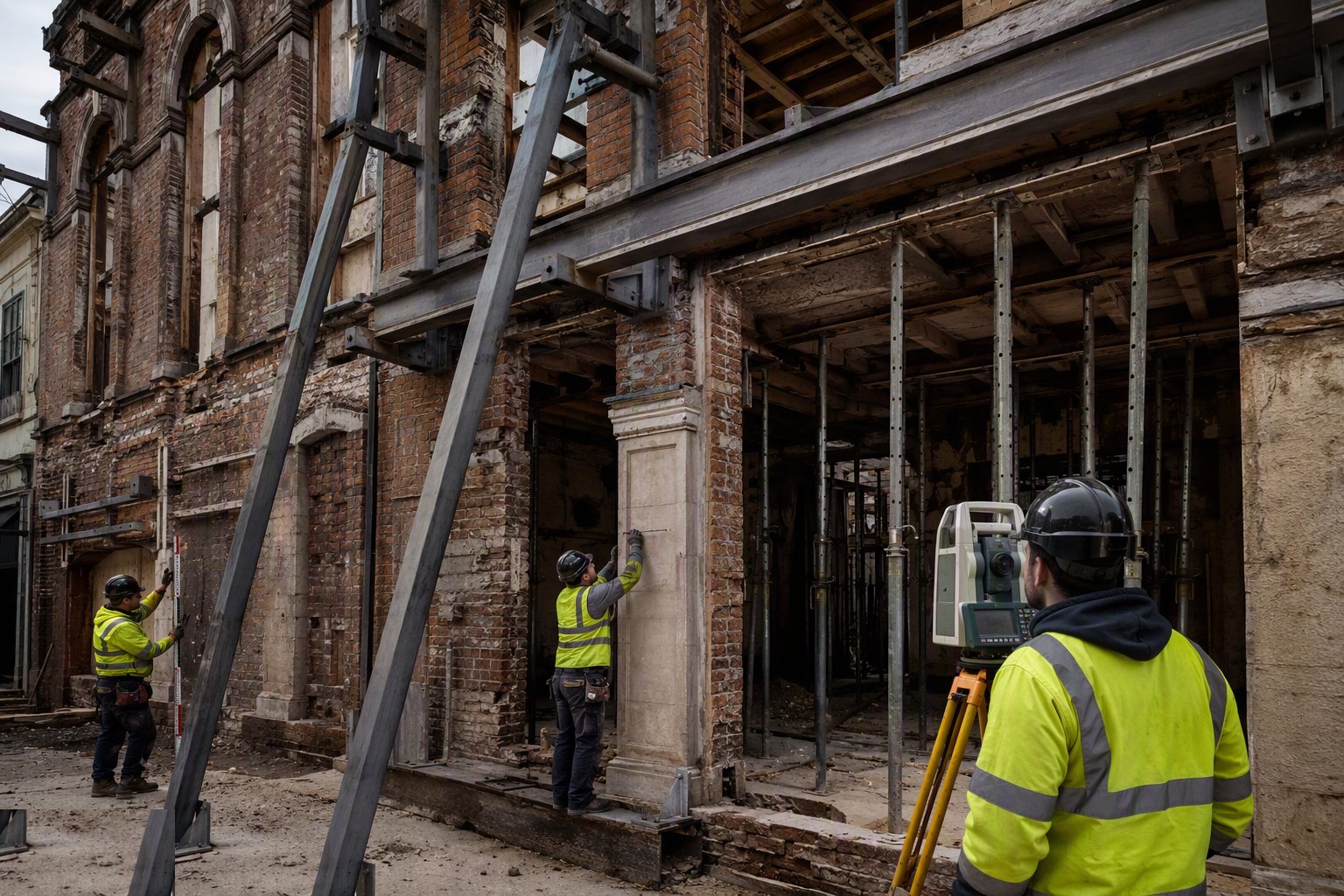
Before any support is designed, the building is surveyed and opened up: wall thicknesses, floor constructions, timber condition, existing cracks tell-taled and levelled. The temporary works designer needs real loads — storey heights, masonry densities, roof construction — not assumptions. Trial holes confirm what the wall is actually built of; a 1900s London stock brick wall and a rendered rubble wall of the same thickness carry and shed load very differently.
Step 2: Design the scheme and agree the sequence
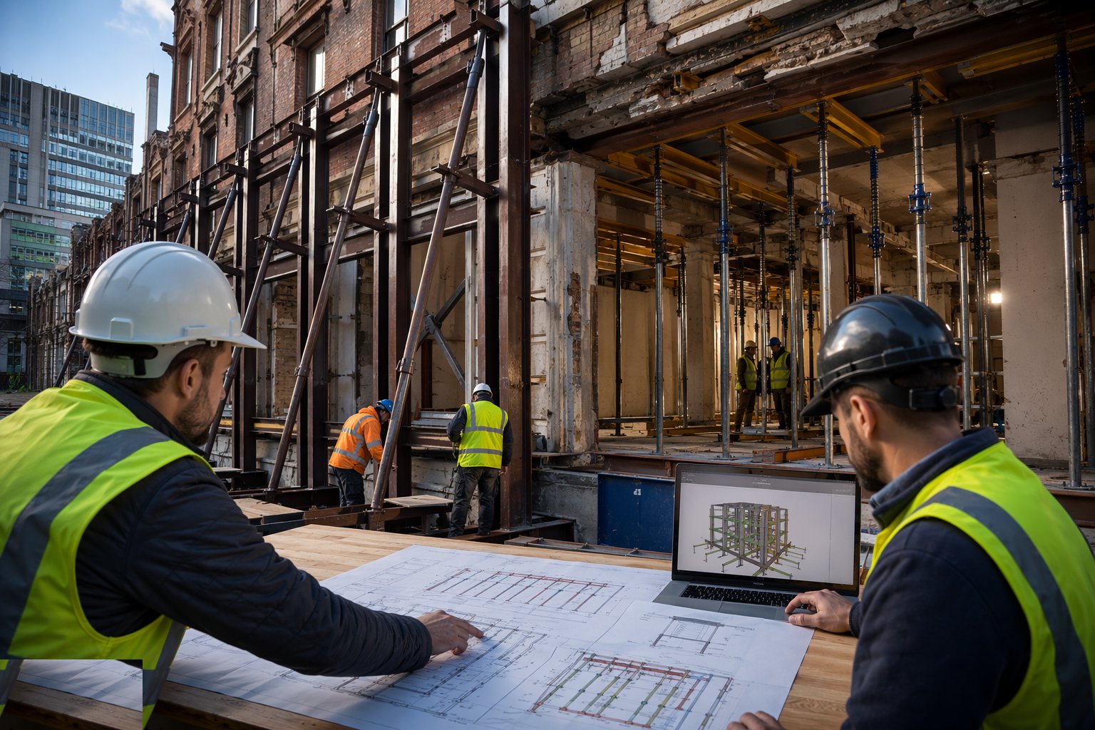
The temporary works designer produces the scheme: prop sizes and centres, needle spacing, sole plates onto verified ground or existing structure, bracing, and — just as important — the erection and loading sequence drawing. Design check category is assigned per the project's temporary works procedure. On UK party wall jobs the Party Wall etc. Act 1996 notices and awards run in parallel; where the works face a highway, the local authority and hoarding/licence interfaces are agreed now, not when the frame arrives.
Step 3: Pre-load check and baseline monitoring
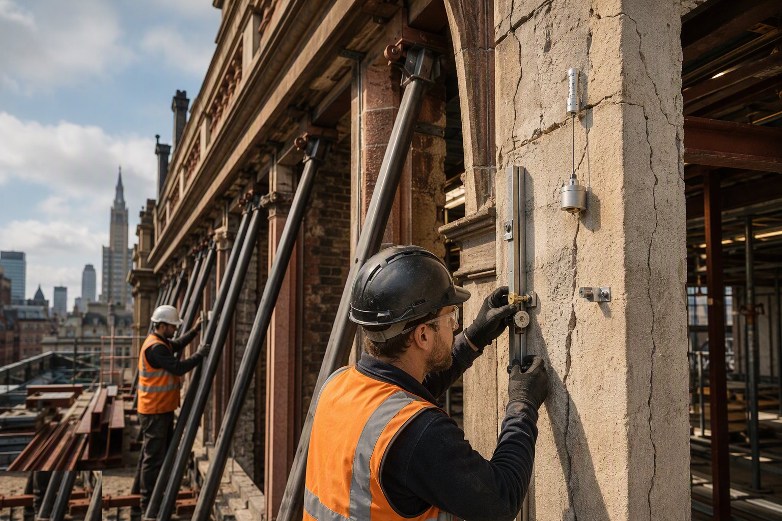
Before the steel goes in, monitoring points are fixed and baselined: precise level studs on the façade, plumb bobs or tiltmeters at the parapet, crack gauges across existing cracks. Baseline readings are taken over several days so thermal and traffic movement is understood. Trigger levels — green/amber/red with named actions — are written into the inspection and test plan and briefed to everyone who will read a gauge.
Step 4: Install needles, props and shores in sequence
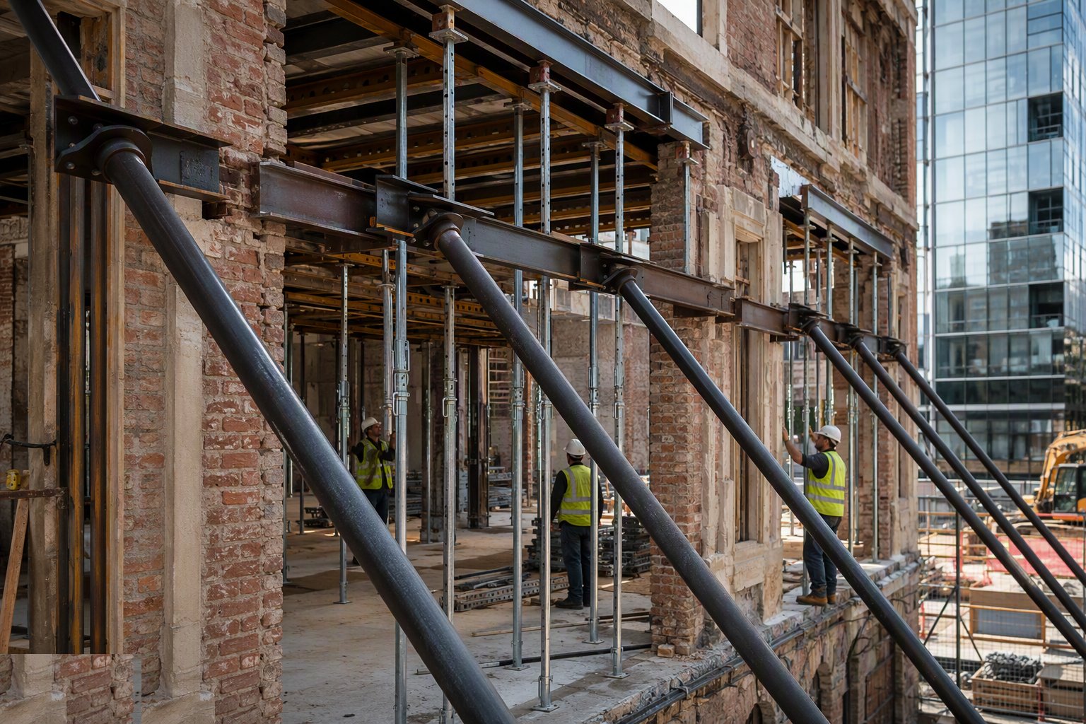
Needle holes are cut at the designed centres — alternating, never a continuous slot — and the needles threaded and seated on sound bearings. Props are plumbed, pinned and pre-loaded with wedges, screw jacks or flat jacks to the specified load so the support is actually carrying before the wall is cut. Raking shores land on sole plates bearing on verified ground; every prop base gets a check that what it stands on can take it.
Step 5: Erect the façade retention frame
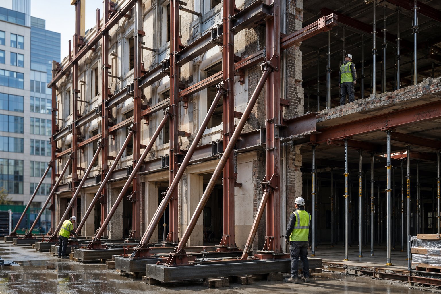
On retention schemes the frame goes up first: grillage or kentledge bases, columns, waling beams against the façade with spreader plates through to sound structure, and the bracing that makes it a frame rather than a fence. Connections to the façade are through pre-drilled holes into engineered fixings, tightened to torque — a frame that leans on the façade without being tied to it is scenery, not support.
Step 6: Hand over to demolition behind the support
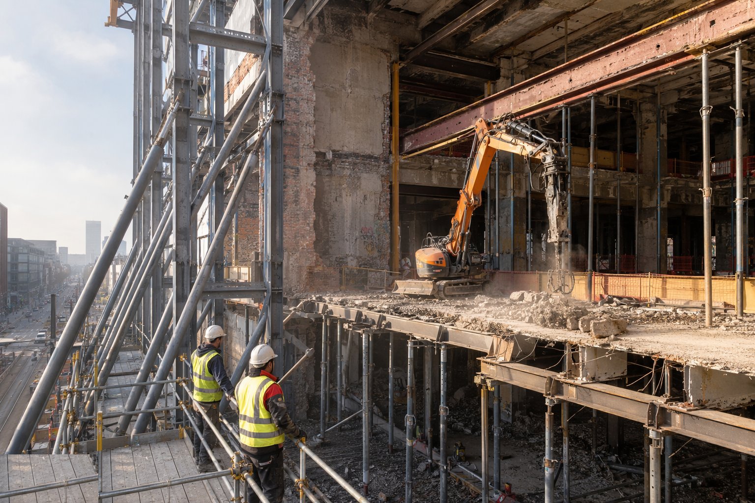
Only after the Temporary Works Coordinator signs the permit to load does demolition start — top-down, remote plant where possible, and never pulling structure towards a retained façade. The demolition method statement respects the support: no excavator arms over needle lines, no stockpiles against shores, no saw-cutting below a needle level until the next row is in. Monitoring frequency increases during this phase.
Step 7: Monitor, inspect and respond to triggers
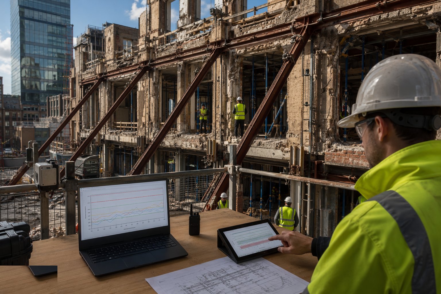
Readings are taken at the specified frequency — daily during active demolition, weekly once stable — plotted against the baseline and the trigger levels. Amber means investigate and re-check torques, wedges and bearings; red means stop, exclude and call the designer. Props are re-torqued as the building relaxes onto the support; a prop that has gone loose has stopped working, whatever it looked like last week.
Step 8: Build the permanent works and transfer load
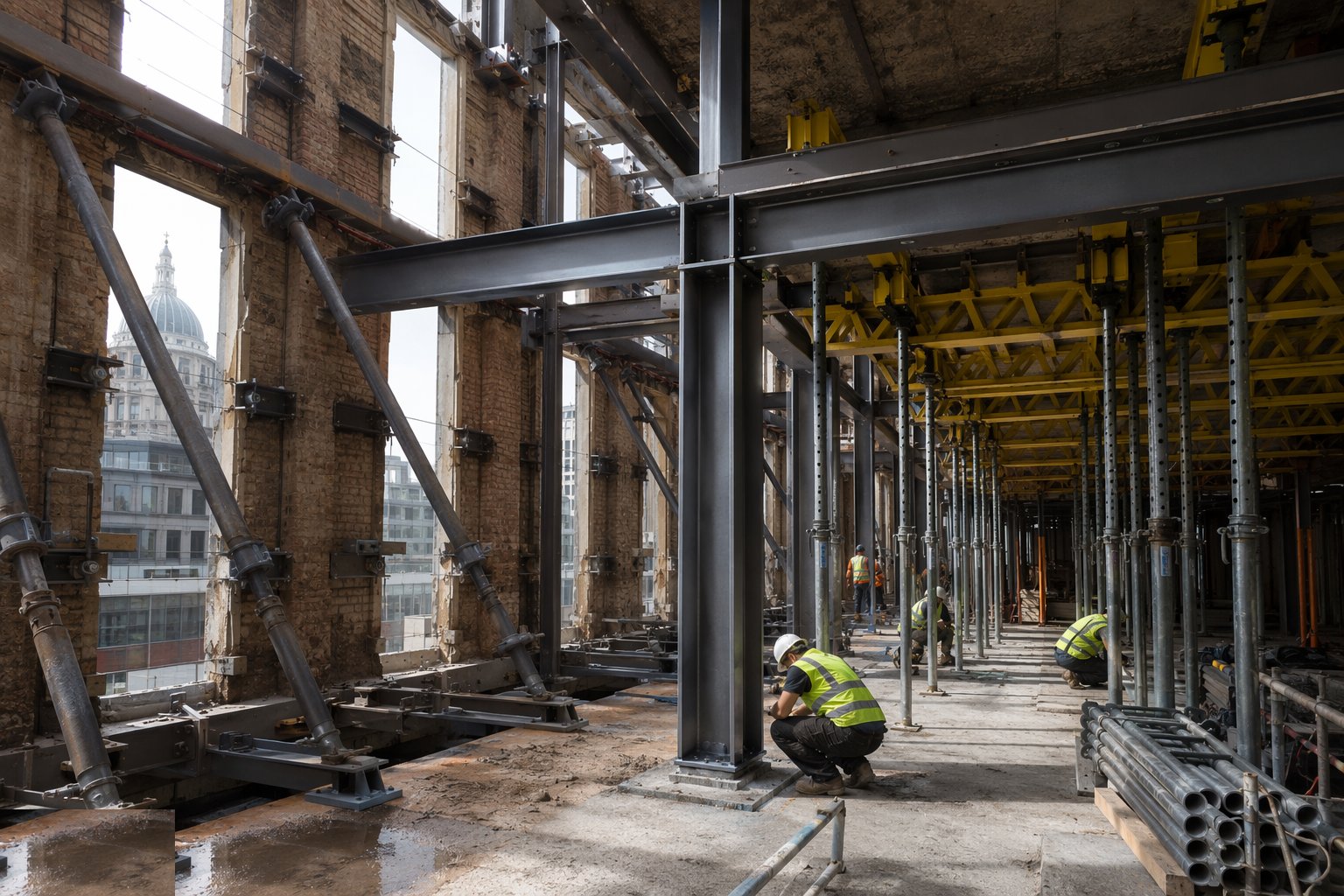
The new beams, columns or walls go in with their bearings grouted solid and their connections complete. Load transfer happens only when the permanent structure has reached the specified strength — cube results or maturity data, recorded — and then gradually: wedges eased, jacks lowered in stages, monitoring watched as the load moves. A jump on the gauge during de-propping means stop and reassess.
Step 9: De-propping, making good and close-out
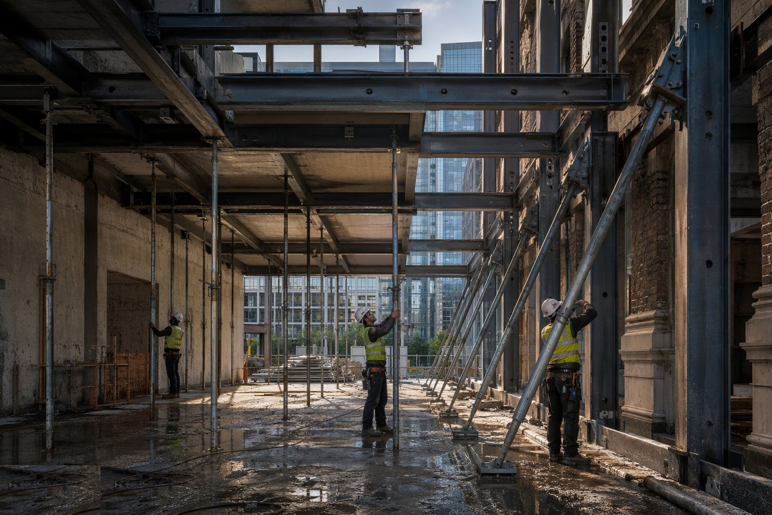
Support comes out in the reverse logic of the design — never the prop that is easiest to reach first. Needle holes and fixing points are made good in matching materials, monitoring continues for an agreed tail period, and the file closes with the as-installed records, load transfer evidence and final readings handed to the permanent works and, on listed façades, the conservation officer.
Plant and equipment
- Adjustable steel props (acrow-style) and high-load proprietary propping systems
- Universal beams and columns for needles, walings and shores
- Hydraulic flat jacks and screw jacks for controlled pre-loading
- Mobile crane or telehandler for frame erection
- Torque wrenches for frame connections; wedges and sole plates
- Monitoring kit: precise level, total station, tiltmeters, crack gauges, tell-tales
- Diamond drilling and sawing kit for needle holes and fixings
- Hoarding, fans and debris protection at street interfaces
Quality control checks
- Temporary works design and check certificates in place before erection
- Prop and needle bearings onto verified structure or tested ground — recorded
- Pre-load values on every prop/jack logged at installation and re-checks
- Baseline and ongoing monitoring readings plotted against trigger levels
- Connection torques on retention frames checked and marked
- Load transfer authorised on permanent-works strength evidence, with staged de-propping records
- Permit to load / permit to strike issued by the Temporary Works Coordinator
Safety considerations
- Collapse is the killer: no structural removal before support is installed, loaded and permitted
- Exclusion zones below and behind walls being needled or demolished
- Street interface: double hoarding, fans, and highway authority licences where frames oversail the pavement
- Manual handling of heavy steel — mechanical aids and planned rigging for needles
- Stored energy in wedges and jacks: controlled release only, no cutting props out
- Competent erectors under a method statement; Temporary Works Supervisor on site
- Party wall and neighbour liaison maintained — movement affects the building next door first
Common defects
- Props onto unverified ground or suspended timber floors that quietly crush under load
- Needle holes cut as a continuous slot, severing the wall they were meant to support
- Loose props after the building relaxes — support installed but never re-torqued
- Façade fixing into decayed masonry that pulls out under wind load
- Demolition pulling structure towards the retained façade and jacking it off its bearings
- Monitoring installed but nobody reading it — triggers breached with no response
- Early de-propping on programme pressure before permanent works reach strength
Best suited for
- Demolition-behind-façade schemes on listed and conservation-area commercial buildings
- Wall removals and opening enlargements in loadbearing masonry housing and villas
- Basement insertions and underpinning beneath occupied buildings
- Party wall support where a neighbouring structure is demolished first
- Any structural alteration where the loads must be carried by something during the works
How long does Propping, Façade Retention and Temporary Support take?
Typical duration: A needle-and-prop scheme for a single opening: 1–2 weeks including design lead-in. A full façade retention frame on a commercial block: 6–12 weeks to erect, then standing for the duration of demolition and rebuild — often 12–18 months. Monitoring runs throughout..
Related processes
- Temporary Works — Design, Control and the TWC
- Scaffolding and Access Systems
- Vertical Formwork — Wall, Column, Climbing and Jump Form
- Horizontal Formwork and Falsework
- Excavation Support and Trench Shoring
- Craneage and Lifting Operations
- Hoists, Mast Climbers and Material Handling
- Construction Plant and Equipment
- Temporary Works & Plant sector guide
- Buildings group