Excavation Support and Trench Shoring
Keeping the sides of a hole standing — battered slopes, trench boxes, hydraulic walings and sheet piles — because a cubic metre of soil weighs about two tonnes and it does not warn you.
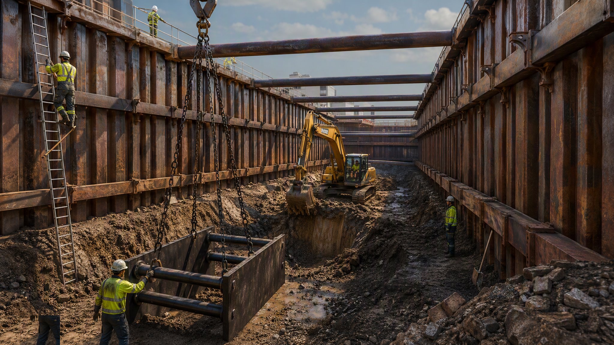
Last updated 2026-07-28 by the BuildPedia Editorial Team.
What is Excavation Support and Trench Shoring?
Excavation support is where construction most often kills people quietly. Trench collapses do not give warnings a man in the bottom of the trench can react to: a cubic metre of soil weighs 1.6–2.2 tonnes, and a collapse at chest height is usually unsurvivable. The HSE statistics make the point bluntly — excavation work is a small fraction of construction activity but a persistent source of fatalities, and the victims are typically in unshored trenches under 2 m deep that "would only take an hour". That is why support is non-negotiable: in the UK, CDM requires every excavation to be supported or battered unless a competent person has inspected and confirmed no risk of collapse, and in practice that means nearly every trench gets support.
The first decision is batter or support. Battering — cutting the sides back to a safe angle, typically 1:1 to 1:2 depending on the soil — is always preferable where space allows, because there is nothing to fail. Where space does not allow, and on constrained UK housing plots and UAE villa plots it rarely does, the options are proprietary: trench boxes dragged along as the pipe or duct is laid, hydraulic waling frames that clamp the trench sides with adjustable struts, drag boxes for continuous utility runs, and trench sheets or sheet piles driven ahead of the dig for deeper or wetter ground. In UAE coastal plots the high water table turns a simple trench into a dewatering and support problem at the same time — running sand will flow under and around any support that was not designed for it.
Every support decision is a ground decision. The soil classification, the water table, the surcharge from spoil heaps and passing plant, and the vibration from adjacent traffic all change what the sides will do. The assumptions are written in the temporary works design; the site's job is to check daily that the ground is still doing what the design assumed, because rain overnight changes the answer. Deeper permanent excavation support — contiguous piled walls, diaphragm walls, propped basement boxes — is a separate, heavier discipline covered in the basement works pages; this page is about the everyday trenches and shallow excavations where most of the exposure sits.
When and why is Excavation Support and Trench Shoring used?
Support is needed wherever people enter an excavation — drainage runs, service ducts, foundation trenches, manholes, inspection pits. Battering is used where the plot has room and the soil will stand at a stable angle; proprietary support is used on constrained plots, near adjacent structures, and anywhere the dig must be vertical. Sheet piling earns its keep for short-term deeper works — pump sumps, deep manholes, works next to live services or roads. The trigger depths that matter on site: any trench a person can enter is assessed, and anything at or below 1.2 m gets support, batter or benching by default on a well-run site, whatever the soil looks like at 8 am.
Types of Excavation Support and Trench Shoring
Battered or benched excavation
Sides cut back to a stable angle or stepped in benches — no proprietary kit, no failure mode except the angle itself. The default choice wherever the footprint allows it; slope angle set by soil type, water and surcharge.
Trench boxes and drag boxes
Steel box panels lowered into the excavated trench and pulled along as the pipe or duct is laid ahead — the worker always stays inside the box. Drag boxes are the same idea sized for continuous utility laying by an excavator.
Hydraulic waling frames
Proprietary frames of hydraulic struts and waling rails, assembled and pressurised against trench sheeting or the ground itself as the excavation descends in stages. Fast to install and remove, adjustable, and the modern default for service trenches and manholes.
Trench sheets and sheet piling for short-term works
Interlocking light sheets or Z-piles driven ahead of the excavation and braced with frames — for deeper sumps, wet ground, and digs tight against roads or live services where ground loss behind the face is unacceptable.
Excavation Support and Trench Shoring: step by step
Step 1: Classify the ground and check the services
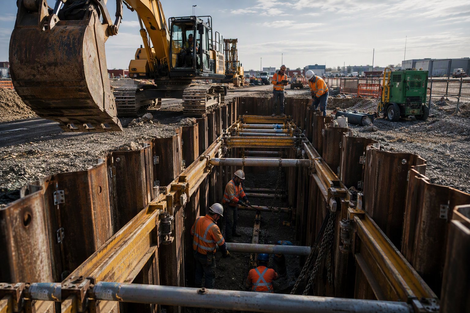
Before the bucket touches ground: service drawings, CAT scan and trial holes to find what is buried — a live 11 kV cable or a gas main changes the whole method. Assess the soil: made ground, clay, sand, gravel, and the water table position. On UAE coastal plots assume water until proven otherwise; on UK brownfield assume made ground and old foundations. These facts feed the temporary works design, not site folklore.
Step 2: Design the support or batter
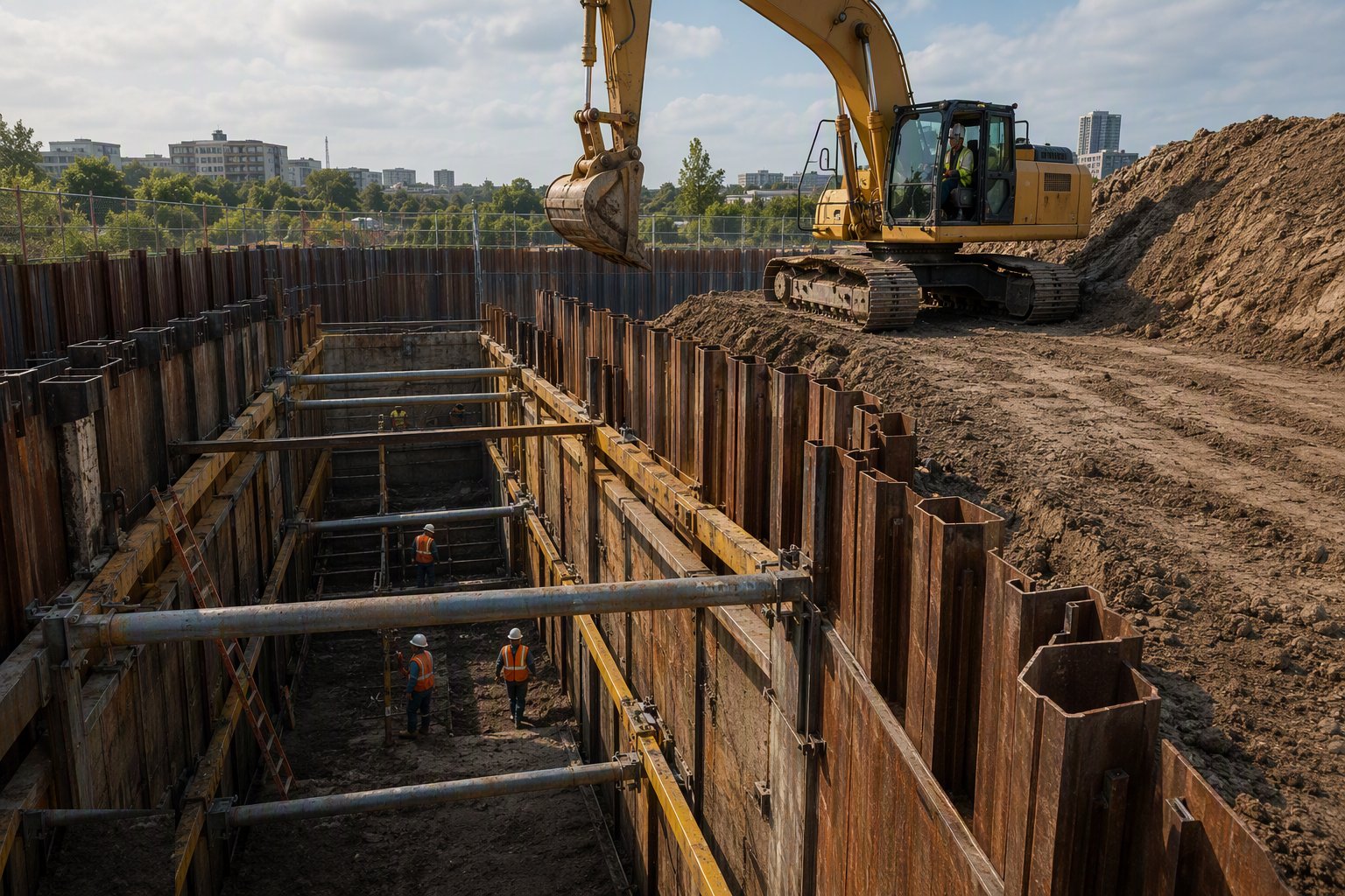
The temporary works designer sets the batter angle or selects the support system for the soil, depth, water and surcharge — including the excavator standing at the edge and the spoil heap, which most designs limit to a set-back distance. Proprietary systems are used within their tabulated data or designed outside it. The permit to dig is raised with the method, the support drawings and the inspection regime attached.
Step 3: Set up edge protection and access
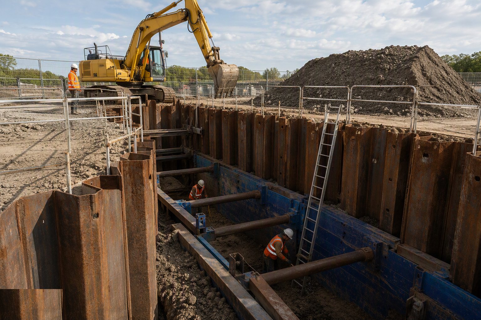
Before anyone descends: guardrails or barriers around the excavation, spoil and plant kept back from the edge (typically at least the depth of the dig for spoil), and a ladder within the trench so nobody is ever more than a few metres from a way out. Ladder access, not jumping, and never climbing the support. Vehicle stop blocks go in where tippers approach the edge.
Step 4: Excavate in stages, installing support as you go
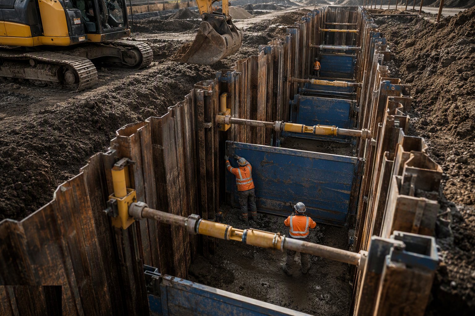
The cardinal rule: support follows the dig down, never the other way round. Excavate 300–500 mm, install and pressurise the frame or place the sheeting, then dig the next stage. Nobody enters unsupported ground at any stage — the first frame goes in from outside the trench or in a shallow first cut. Trench boxes are lowered into a slightly over-deep dig and the sides backfilled and compacted against them so the ground cannot run.
Step 5: Manage water as it appears
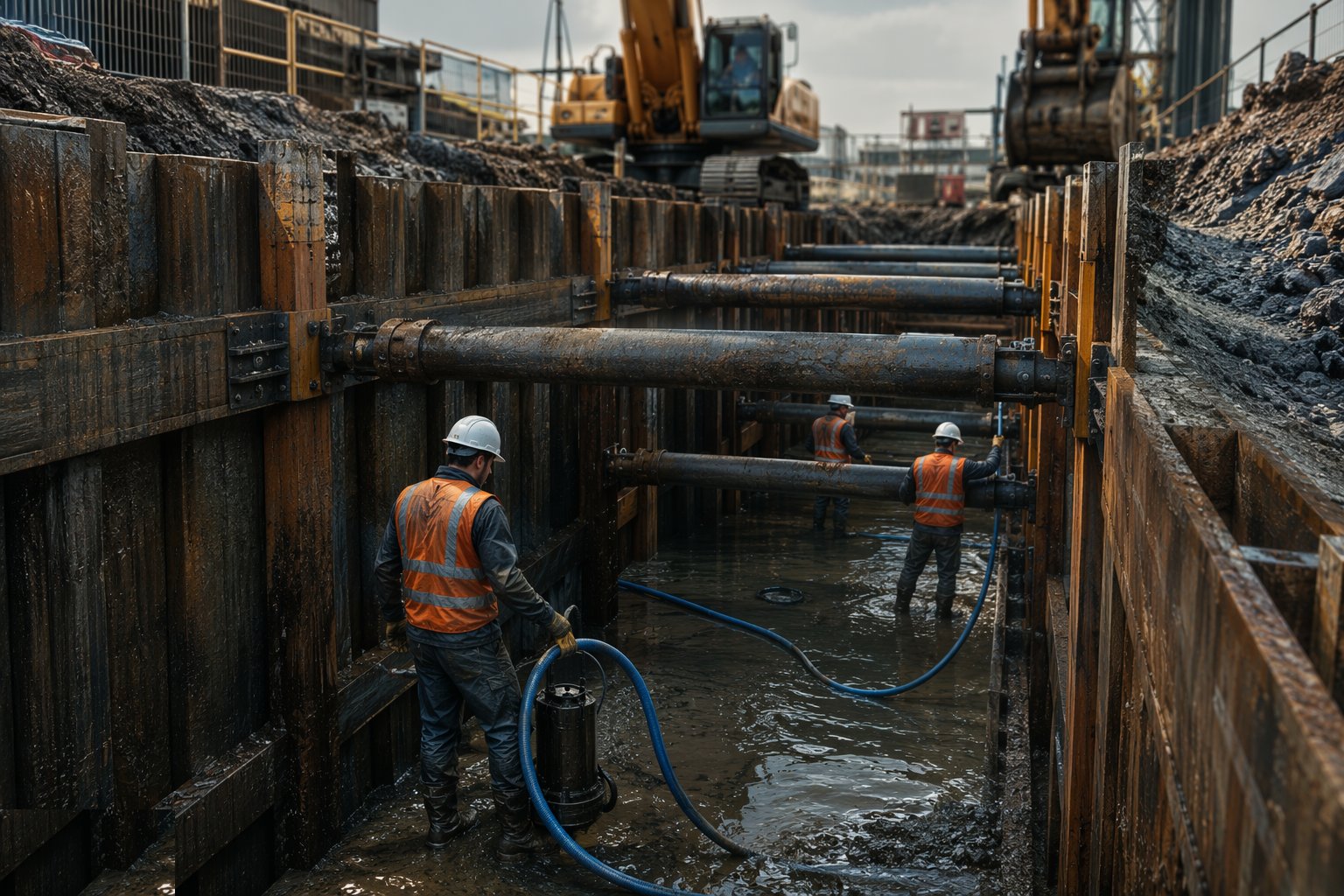
Water is pumped from sumps within the supported zone — never by digging a deeper unshored pocket to hide it in. In sands, pumping from inside the trench can draw fines and collapse the face from below; the design says whether pumping is allowed or external wellpoints are needed. Inflow that appears where the design said dry is a stop-and-check event: the ground is not behaving as assumed.
Step 6: Install the permanent work inside the support
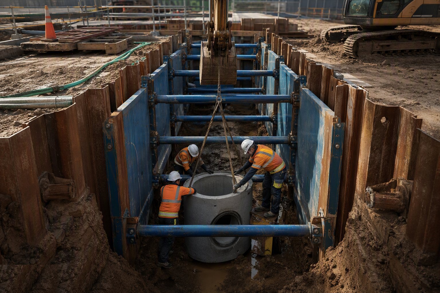
Pipe, duct, manhole or foundation goes in with everyone working inside the box or between the frames. Bedding and surround are placed and compacted in layers — the voids between support and trench face are filled as the support is raised or withdrawn, so ground cannot relax into the gap. Drag boxes move forward only when the run behind is bedded and the next section of trench is open.
Step 7: Inspect daily and after every event
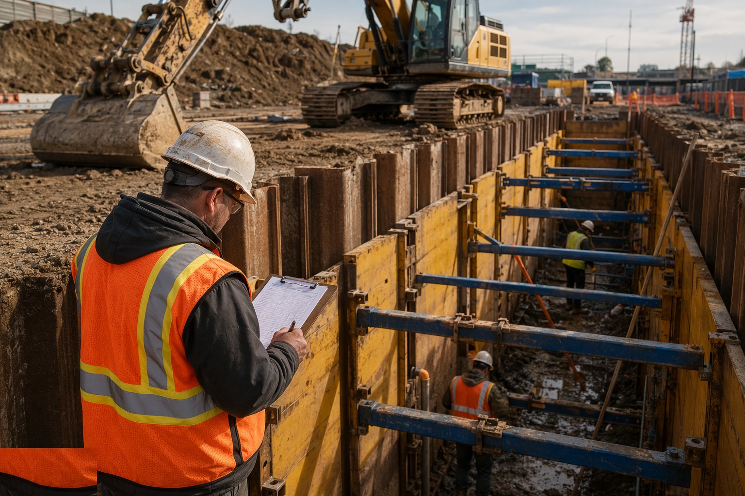
A competent person inspects the excavation at the start of every shift, after rain, after any ground movement, and after any nearby plant or vibration event — and the inspection is recorded. Look for tension cracks at the surface, slumping at the toe, water seepage lines on the face, and struts that have gone slack or bowed. Any of these means nobody goes in until the cause is understood.
Step 8: Withdraw support and backfill in controlled stages
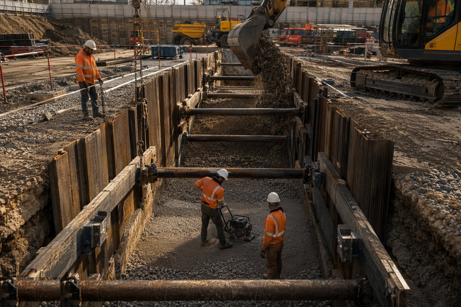
Support comes out as the backfill goes in, in stages that keep the face supported for as long as possible: compact a layer, raise the frame or pull the sheets to the next level, repeat. Sheets are pulled with vibration where specified, and the void left by a pulled sheet is filled as it forms — a gap left overnight becomes a settlement trough under someone else's road by spring.
Plant and equipment
- Excavator with quick-hitch buckets; vacuum excavator near live services
- Trench boxes and drag boxes in modular sizes
- Hydraulic waling frame systems with hand pumps and pressure gauges
- Trench sheets, Z-piles and a vibratory hammer or excavator-mounted driver
- Pumps: submersible, diaphragm for slurries; wellpoint kit for running sand
- Ladders, edge protection barriers and stop blocks
- CAT scanner and signal generator for service location
- Gas detector for deep or contaminated-ground digs
Quality control checks
- Permit to dig issued with service scans and trial-hole records attached
- Support system used within tabulated data or designed, with check certificate
- Daily competent-person inspection recorded; post-rain and post-event re-inspections
- Surcharge set-backs observed — spoil and plant positions against the design limits
- Bedding, surround and backfill compaction tested at specified layer frequencies
- Frame pressures and strut condition checked at every stage change
- Withdrawal sequence recorded, with void treatment behind pulled sheets
Safety considerations
- No entry to unsupported ground — ever, at any depth, "just for a minute" least of all
- Collapse is the fatal risk: assume the face will fail and stay inside the support
- Edge protection and set-backs keep plant and spoil loads off the face
- Ladder access within the supported zone at all times; ladders extend above the edge
- Gas testing in deep, confined or contaminated digs before and during entry
- Adjacent structures: movement monitoring where digging near foundations or walls
- Night and poor-visibility working: lighting of the excavation edge and the dig itself
Common defects
- Trench dug to full depth then "boxed" — the unprotected stage is where collapses happen
- Gaps between box panels and trench face left unfilled, letting ground run and settle
- Spoil heaped at the edge, loading the face the design assumed was unloaded
- Support removed early to lay the next pipe run faster — the classic fatality sequence
- Water pumped from an unshored sump pit that undermines the supported face
- Sheets pulled without backfilling the void — settlement appears months later under the road
- Batter cut steeper than the soil will stand because "it looked fine yesterday"
Best suited for
- Drainage, water and utility trenches on housing and villa plots
- Service diversions and connections in constrained urban sites and highway work
- Manholes, pump sumps and inspection chambers below box depth
- Digs adjacent to live services, roads and existing foundations where ground loss is unacceptable
- Wet and running ground where sheet piling controls both the face and the water path
How long does Excavation Support and Trench Shoring take?
Typical duration: A shored drainage trench run: 10–20 m per day with a drag box and a laying gang. A deep manhole in framed support: 3–5 days including base and benching. Battered excavations are as fast as the excavator — the support cost is the space, not the time..
Related processes
- Scaffolding and Access Systems
- Vertical Formwork — Wall, Column, Climbing and Jump Form
- Horizontal Formwork and Falsework
- Propping, Façade Retention and Temporary Support
- Craneage and Lifting Operations
- Hoists, Mast Climbers and Material Handling
- Construction Plant and Equipment
- Temporary Works — Design, Control and the TWC
- Excavation Support and Trench Shoring in Residential & Housing
- Excavation Support and Trench Shoring in Commercial & Workplace
- Excavation Support and Trench Shoring in Roads & Highways
- Excavation Support and Trench Shoring in Water Infrastructure
- Excavation Support and Trench Shoring in Wastewater & Sewerage
- Excavation Support and Trench Shoring in Land Development & Earthworks
- Temporary Works & Plant sector guide
- Buildings group