Precast Concrete Structures
Crosswall, twin-wall, hollowcore, stairs, lift shafts and sandwich panels — the factory-made concrete frame, and why the UAE builds this way by default.
Last updated 2026-07-28 by the BuildPedia Editorial Team.
What is Precast Concrete Structures?
Precast concrete is the oldest and most successful MMC of them all, which is presumably why the MMC conversation keeps forgetting to include it. Walls, floors, stairs, lift shafts, columns, beams and façade panels are cast in a factory or yard under controlled conditions, cured properly, and craned into position where they are stitched together with in situ concrete, grout and reinforcement. The quality argument is settled: factory concrete has better finish, better cover control and better strength consistency than anything poured in the rain off the back of a mixer. The site stops being a concrete factory and becomes an assembly operation with a crane.
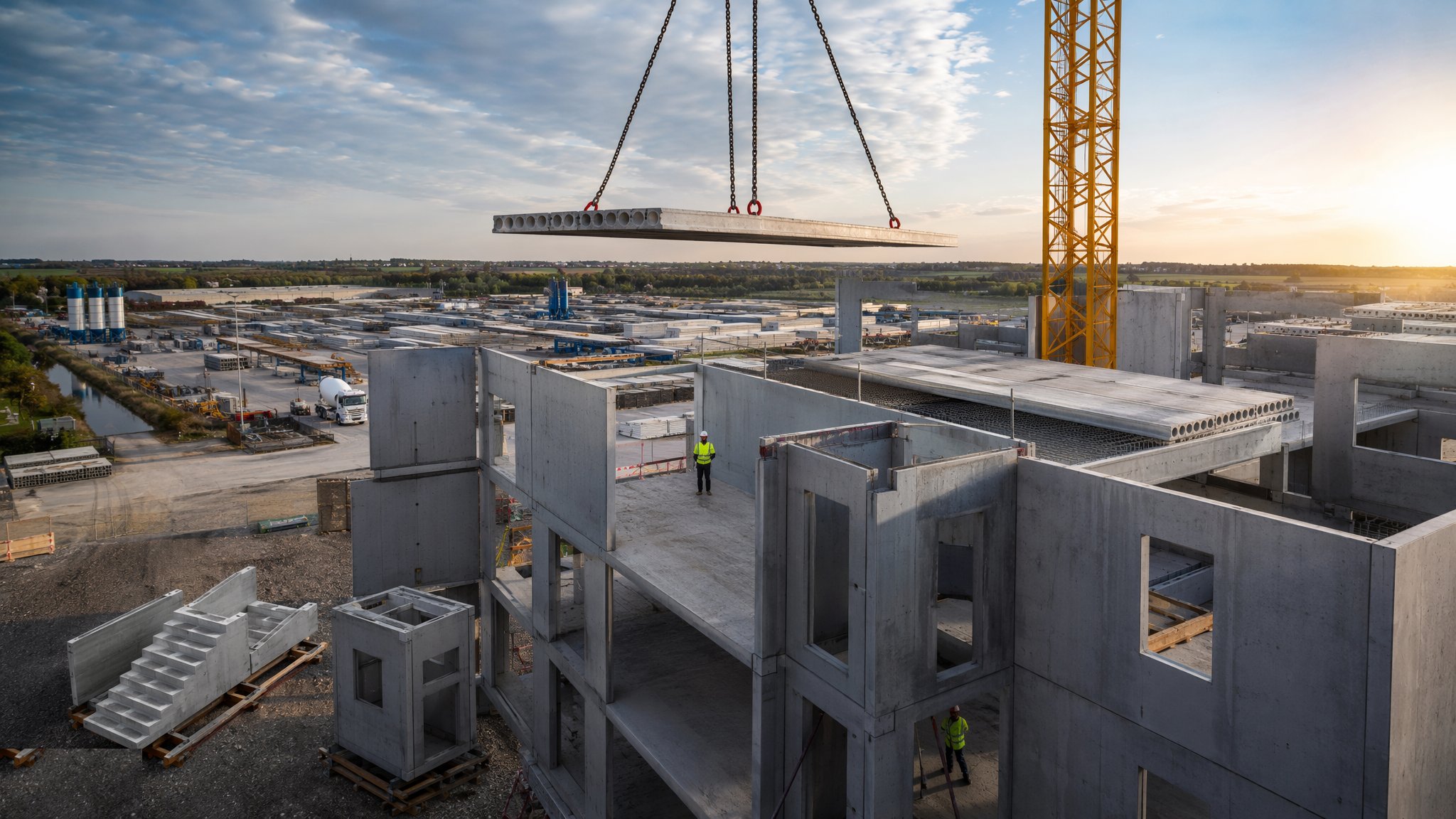
The systems divide by how much is precast. Crosswall construction uses loadbearing precast walls with hollowcore or solid precast floors — the classic hotel and residential-block system, fast and inherently fire- and sound-resistant. Twin-wall is the halfway house: two factory-cast leaves joined by lattice girders, craned into position and filled with in situ concrete to make a solid wall with the ties and laps already in it. Hollowcore planks span between walls or beams as floors with their cores doing duty as service routes and saving dead weight. Around them sit the components every site knows: precast stairs that land in minutes instead of a fortnight of formwork, lift-shaft modules, and insulated sandwich façade panels that are structure, insulation and architectural face in one pick.
Nowhere has taken this further than the UAE, where precast is not an MMC choice but the default. Villa walls across Dubai are precast panels standing on strip or raft foundations, hollowcore floors span the rooms, and the boundary wall of nearly every plot in the emirate is precast — an industry built on DM/DDA-approved standard designs, with the casting yards of Sharjah and Abu Dhabi feeding a supply chain that never stopped. There are hard reasons: the climate punishes site-cast concrete (48 °C afternoons, hot-weather concreting rules, curing that never quite happens on site), the labour model suits factory production over formwork carpentry on site, and repetition is total — a thousand villas of the same five types is a factory order book, not a design problem.
The trade-offs are the same everywhere. Precast is heavy, so craneage and transport are real costs and the design grid is set by what a lorry and a crane can handle. Connections — grouted sleeves, bolted plates, welded plates, dowelled hollowcore bearings — are engineered points in an otherwise monolithic material, and they demand the tolerance discipline that in situ work lets you fudge. And during erection the frame is a kit of parts held up by props and temporary bracing until the stitches gain strength: the stability case is a temporary-works design, not an assumption.
When and why is Precast Concrete Structures used?
Precast wins on repetition, programme and quality: residential blocks, hotels, student housing, car parks, prisons and anywhere the same bay repeats. Crosswall suits cellular plans where walls can carry load; twin-wall suits where cast in situ robustness is wanted without formwork; hollowcore floors span economically with few props. In the UAE it is the default for villas, boundary walls and much mid-rise work — DM/DDA-approved standard systems, factory quality in a climate hostile to site concrete, and a mature yard supply chain. It loses on one-off geometry, heavy transfer structures, sites with no crane standing, and designs that are still moving after the moulds are ordered.
Types of Precast Concrete Structures
Crosswall frames
Loadbearing precast concrete walls at room-width centres carrying hollowcore or solid precast floors. The hotel, student-block and residential system: monolithic once stitched, excellent fire and sound performance, very fast per floor.
Twin-wall systems
Two precast leaves joined by lattice girders, erected and filled with in situ concrete — factory accuracy and finish with a monolithic core. Walls go up without formwork; the fill pour ties walls, floors and stitches into one structure.
Hollowcore floors and stairs
Prestressed hollowcore planks spanning 6–12 m between supports, grouted at joints, with precast stair flights and landings craned in per storey. The workhorses of precast: fast, soffit-flat, minimal propping.
Sandwich façade panels and lift shafts
Insulated sandwich panels — structural inner leaf, insulation core, architectural outer face — hung on the frame as the finished envelope in one pick; plus precast lift-shaft modules stacked like blocks. Cladding and core solved as products, not trades.
Precast Concrete Structures: step by step
Step 1: Fix the grid, the tolerances and the connection design
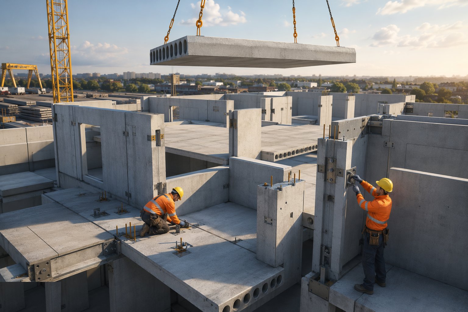
Precast design locks early: the structural grid, panel sizes within transport and crane limits, bearing lengths, and every connection detail — grouted sleeves, dowels, bolted or welded plates, hollowcore bearing strips. Tolerances are allocated across the chain (foundation, unit, erection) so they do not stack up at the worst joint. In the UAE this stage runs through DM/DDA or Trakhees approval of the precast system and shop drawings before the moulds are touched.
Step 2: Cast and cure in the yard, with QC the site cannot match
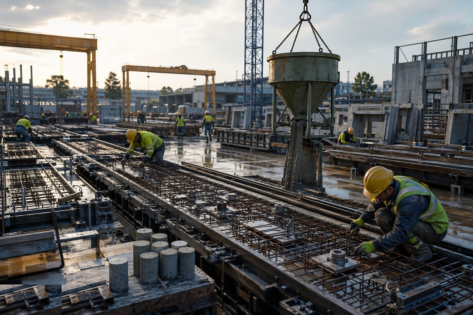
In the casting yard, reinforcement and cast-in items — lifters, sleeves, connection bars, plates — are fixed in the moulds, inspected, and concreted under controlled batching with cube or cylinder sets per cast. Curing is managed (steam or controlled heat in many yards), demould times follow strength results, and every unit is marked, dimension-checked and logged before it leaves the bed. The paper trail per unit — cast date, results, mark — is what the site will demand when a panel looks wrong.
Step 3: Transport, stack and sequence the deliveries
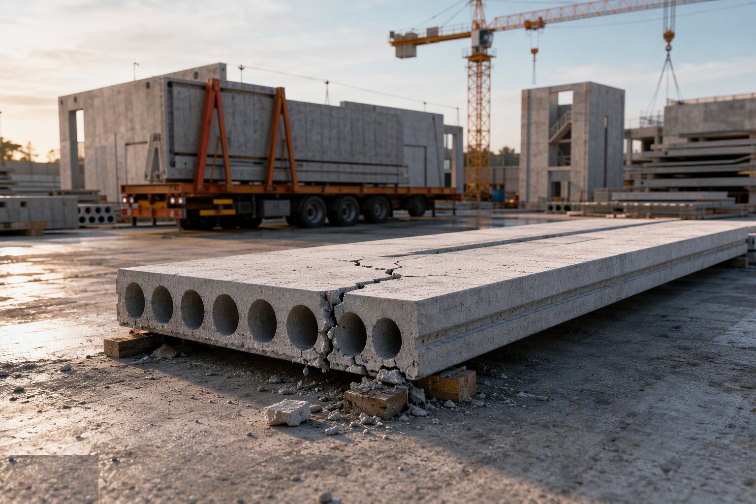
Units travel on A-frames and flatbeds in erection order, supported at their designed points — a hollowcore plank stored on the wrong bearers cracks before anyone lifts it. The site stacks on level, firm ground with bearers aligned vertically through the stack, and the delivery schedule is matched to the crane: just-in-time is the aim because a site full of stacked panels is a handling accident and a wind-load problem waiting to happen.
Step 4: Set out, level the bearings and start the walls
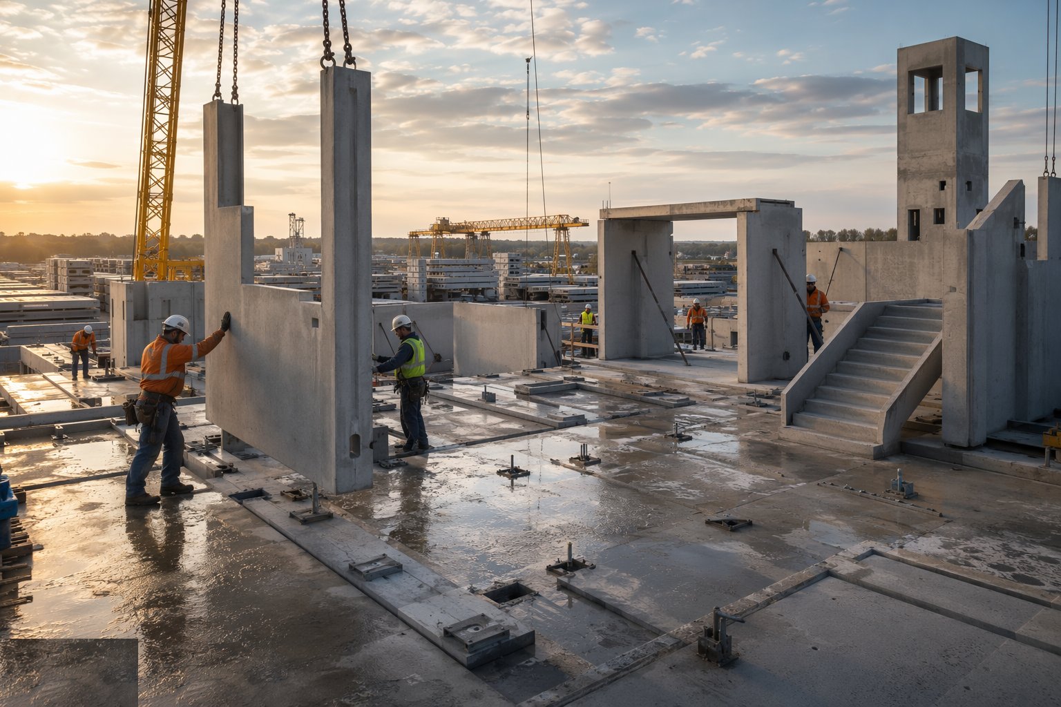
Foundation or slab bearings are surveyed to the erection tolerance — level pads, grout beds or shims per the detail — and wall panels are lifted on their designed anchors, set to line, plumbed and braced or propped immediately. The first panels establish the grid truth for the whole floor; connections to starters and sleeves are made as each panel lands, not in a batch later.
Step 5: Land floors, stairs and shafts on the wall plates
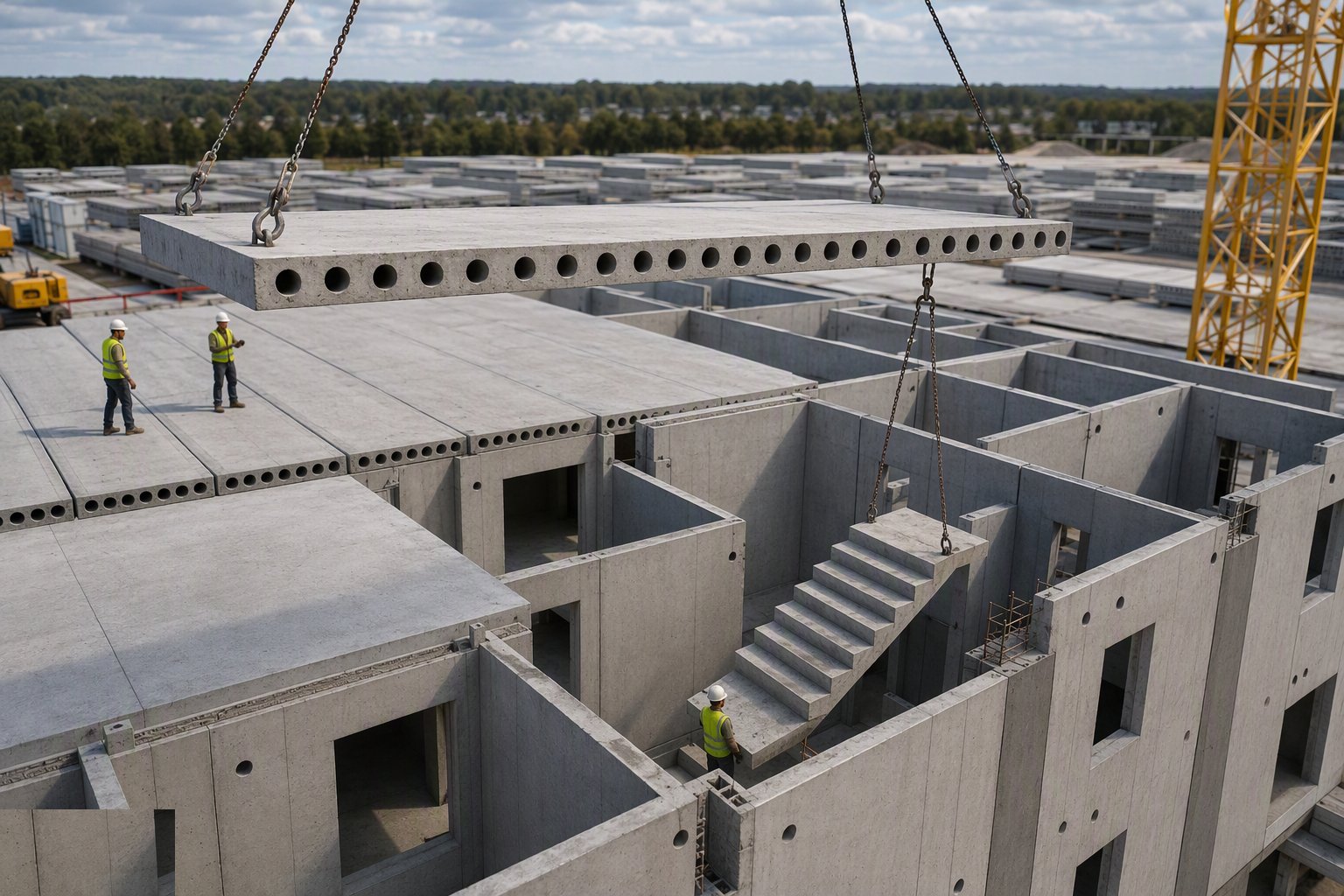
Hollowcore planks land on their bearing strips with the specified bearing length, jointed and grouted; precast stairs drop between landing levels in minutes with their bearings and ties made; lift-shaft modules stack with their inter-unit connections. Propping goes in where the design calls for it — planks carrying construction load, edge conditions, twin-wall awaiting its fill — and stays until the stitch concrete has the strength, not until the programme wants it gone.
Step 6: Make the connections — grout, bolts, welds and stitches
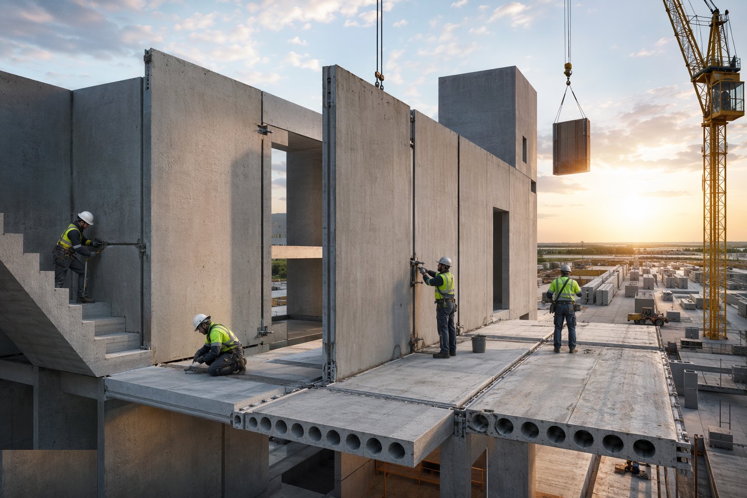
This is the structural heart of the method. Grouted sleeve and dowel connections are filled with the specified non-shrink grout, flowed and vented properly, with test cubes; bolted and welded plate connections are torqued or welded to procedure and inspected; in situ stitch concrete between walls and floors is placed, vibrated and cured. Twin-wall gets its core fill in controlled lifts. Every hidden connection is photographed and recorded before the next unit buries it.
Step 7: Hold stability through the temporary-works design
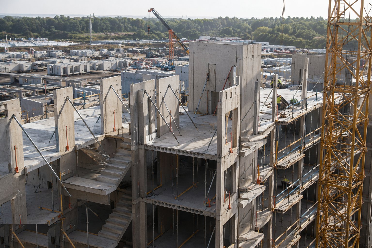
Until the stitches and fills reach strength, the building stands on its temporary works: panel braces, floor props, hold-downs and the erection sequence itself. The temporary-works designer owns the stability case — wind on unbraced panels, incomplete diaphragms, crane loads on part-strength floors — and the site does not strike a prop or load a floor without the strength evidence. Most precast collapses worldwide happen in exactly this window.
Step 8: Survey, seal the joints and hand the structure over
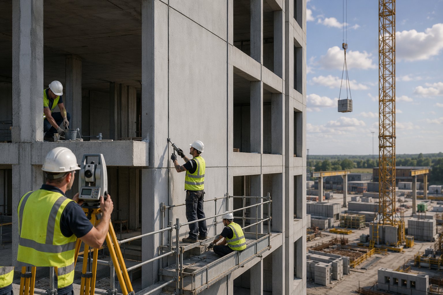
As-built survey records line, level and plumb per floor; joints between façade panels are sealed with the specified system; bearing and joint grouts are checked for fill. The structure hands over to follow-on trades with cast-in channels, plates and sleeves exactly where the drawings put them — which is the last discipline of precast: there is no chasing a concrete wall that was finished in a factory, so first fix works to the cast-in schedule or not at all.
Plant and equipment
- Tower or mobile crane sized for the heaviest unit at the working radius
- Lifting beams, chains and proprietary lifting-anchor tackle with certificates
- Panel props, braces and temporary-works kit with a checked design
- Grout pumps, mixers and flow-test kit for sleeve and joint grouting
- Torque wrenches and welding sets for plate connections
- A-frames, stillages and transport bearers for unit storage
- Survey kit: total station and lasers for bearing and plumb control
- Twin-wall fill kit: pump, tremie pipes and vibrators for core concrete
Quality control checks
- Yard QC: mould checks, reinforcement inspection, cast records and strength results per unit
- Unit identity, dimensions and camber checked on receipt against the cast schedule
- Bearing levels, lengths and grout beds surveyed and signed off per floor
- Grouted connections: flow tests, cube sets and full photographic records before burial
- Propping and bracing in place per the temporary-works design, with strength evidence before striking
- As-built survey of line, level and plumb per floor against the erection tolerances
- DM/DDA or Building Control inspection stages met with the yard-to-site paper trail intact
Safety considerations
- Every unit is a heavy suspended load — certified lifting anchors, tackle inspection, exclusion zones
- Unbraced panels are freestanding sails: braced before the crane unhooks, wind limits observed
- Temporary stability of the part-built frame — no propping removed without the strength results
- Falls at floor edges and shaft openings the moment planks land — edge protection with the pick
- Grout and concrete work: burns, pump-line exclusion zones, controlled pours
- Lorry and crane interface on a constrained site — segregated marshalling and a banksman's word is final
- Hollowcore stored on wrong bearers cracks silently — stack inspections before lifting
Common defects
- Chipped edges and spalled corners from handling, patched cosmetically over reinforcement
- Hollowcore bearing short of the design length where walls drifted off line
- Grouted sleeves part-filled or unvented — the connection that is not there
- Cracked planks from wrong storage bearers or construction overload on props
- Leaking façade panel joints sealed with the wrong system or none
- Stitch concrete honeycombed at wall-floor junctions from congested reinforcement and poor vibration
- Fit-out chaos where first fix ignored the cast-in schedule and met a finished concrete wall
Best suited for
- Hotels, student blocks and residential towers with cellular, repeating plans (crosswall)
- UAE villas, boundary walls and mid-rise blocks — the regional default for climate and supply-chain reasons
- Car parks and podium decks where hollowcore spans and precast speed pay directly
- Custodial and institutional buildings wanting monolithic fire and sound performance
- Any scheme with the repetition, crane access and early design freeze precast demands
How long does Precast Concrete Structures take?
Typical duration: A precast frame floor cycle: 1–2 weeks per storey once running, against 3–4 for cast in situ. A UAE villa wall set erects in days with the yard lead time (typically 4–8 weeks) upstream. The movers: unit count, crane count and radius, connection complexity, and curing time on the stitches before props come out..
Related processes
- Modern Methods of Construction — What They Actually Are
- Volumetric Modular Construction
- Panelised Systems — Open and Closed Panel
- SIPs, Floor and Roof Cassettes
- Bathroom Pods, Riser and Plant Modules
- Design for Manufacture and Assembly
- Site-Based MMC — Tunnel Form, Jump Form, Slipform, ICF
- Hybrid MMC — Modules on Podiums, Precast on Cores
- Off-Site Logistics, Craneage and Tolerance
- 3D Printing and Additive Construction
- Precast Concrete Structures in Residential & Housing
- Precast Concrete Structures in Commercial & Workplace
- Precast Concrete Structures in Mixed-Use & Urban Regeneration
- Off-Site & Modern Methods sector guide
- Buildings group