Drainage & Utility Corridors
Pipes, ducts, chambers and culverts — the buried networks installed before the pavement goes over them.
Last updated 2026-07-28 by the BuildPedia Editorial Team.
What is Drainage & Utility Corridors?
Every road, bridge approach and tunnel portal sits on top of a hidden network: carrier drains and gullies taking water off the carriageway, filter drains in the verge, attenuation ponds and tanks holding back the storm, and ducts carrying power, telecoms, lighting and signals along the corridor. All of it must go in before the pavement and structures above — which is why drainage and utilities come early and sit squarely on the critical path. A drainage run discovered missing after the blacktop is down means digging up finished work, and nobody forgives that.
In the UK, highway drainage and service ducts are specified to Series 500 of the Specification for Highway Works, with design to the DMRB. Where sewers are to be adopted by the water company they are designed and built to the Sewerage Sector Guidance — the Design and Construction Guidance that succeeded Sewers for Adoption 8th edition — under a Section 104 agreement of the Water Industry Act 1991, with adoption inspections and CCTV surveys before the water company takes them on. Utility apparatus in the highway is coordinated under NRSWA: statutory undertakers have their rights and duties, and diversions of their kit are planned months ahead.
In the UAE the same networks answer to different masters: storm drainage and sewerage to Dubai Municipality, power and water to DEWA, telecoms to e& and du, and anything in the road reserve to the RTA right-of-way permits. Diversions of live utilities are the classic programme risk on Gulf infrastructure — a 132 kV cable corridor does not move quickly — so the diversion schedule is agreed with every utility at design stage, trial-pitted, and tracked on the NOC register until the last chamber is certified.
When and why is Drainage & Utility Corridors used?
Drainage and utility corridors are built after the earthworks formation and before the pavement layers and structures above, because they are the deepest buried services and everything shallower crosses over them. Deep first, shallow later is the iron rule of buried services. Getting them in early also protects the earthworks themselves — a corridor without working drainage is a corridor that floods every time it rains.
Types of Drainage & Utility Corridors
Carrier drains, gullies and highway drainage
The piped network that takes run-off off the carriageway: gully pots and kerb outlets collecting surface water, carrier drains running to outfalls, and filter (fin) drains in verges and central reserves handling both surface and groundwater. Laid to line and level on a granular bed, air-tested and CCTV-surveyed before adoption or handover.
Attenuation and SuDS
Ponds, swales, geocellular tanks and oversized pipes that hold the storm and release it slowly, protecting downstream watercourses. Increasingly adoptable in England under the Design and Construction Guidance; in the UAE, storm networks discharge to the municipal system or soakaways under Dubai Municipality approval, with the discharge consent setting the rate.
Service ducts and chambers
Ducts — typically 100–150 mm — laid in trenches on sand beds for power, lighting, signals and telecoms, with draw pits and chambers at changes of direction and spacing set by the pulling length. Marker tape, draw cords and as-built records are the difference between a duct network and a guessing game for the next forty years.
Utility diversions and crossings
Moving other people's live apparatus: a water main lowered under a new cutting, an HV cable diverted around a bridge foundation, a telecoms duct bank rerouted. The undertaker usually lays the new asset and transfers services live, with outages planned to the minute. Where a live crossing cannot move, it is protected in place — concrete surround, marker slabs, and a no-dig zone policed by permit.
Domestic-scale drainage: soakaways and package plants
The small end of the buried-network trade: a house off mains drainage runs its foul flow to a package sewage treatment plant discharging under environmental consent, and its roof and drive run-off to soakaways sized from percolation tests to BRE Digest 365 — the same infiltration-first hierarchy as the highway network, at garden scale. Bedding, falls, air tests and as-built records matter exactly as much, because no adopting authority inspects them and the owner pays for every failure.
Drainage & Utility Corridors: step by step
Step 1: Set out the runs from the drainage schedules
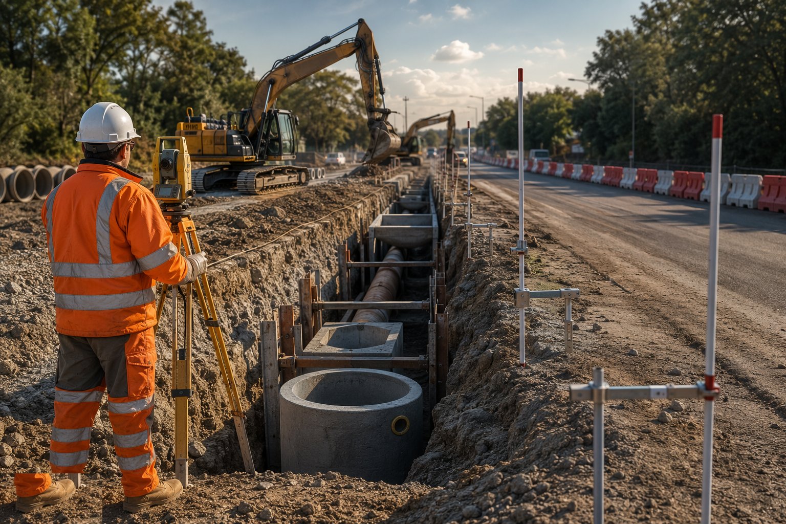
Set out pipe runs, chamber positions and invert levels from the drainage schedules and setting-out data, with profiles and sight rails at every manhole. Check the hydraulic design against the ground truth: outfall levels, existing connections and the invert of the receiving sewer or watercourse — a drain that cannot discharge by gravity is a redesign, not a site fix.
Step 2: Excavate the trenches with support
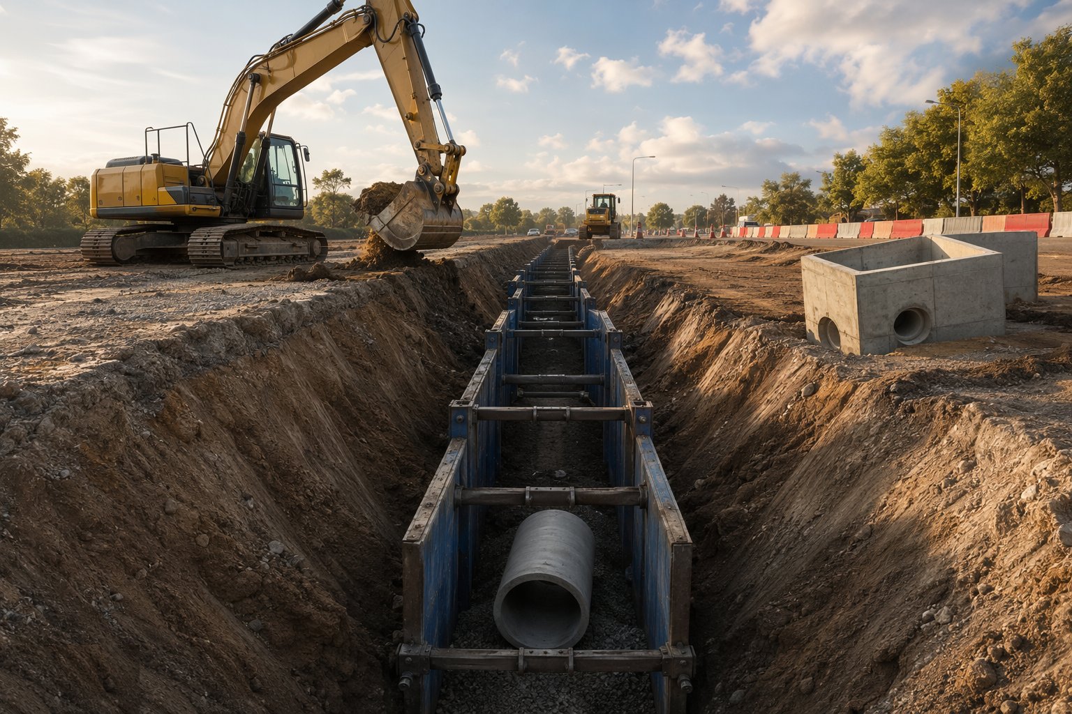
Dig trenches to line and width, keeping the base undisturbed — the last pass shaves to level rather than over-digging. Sides are battered, benched or supported with trench boxes or sheets wherever people enter deeper than about 1.2 m. In water-bearing ground, dewater with wellpoints or sumps outside the pipe bed; in Gulf sands the base stability — boiling or running sand — is watched continuously.
Step 3: Bed and lay the pipes
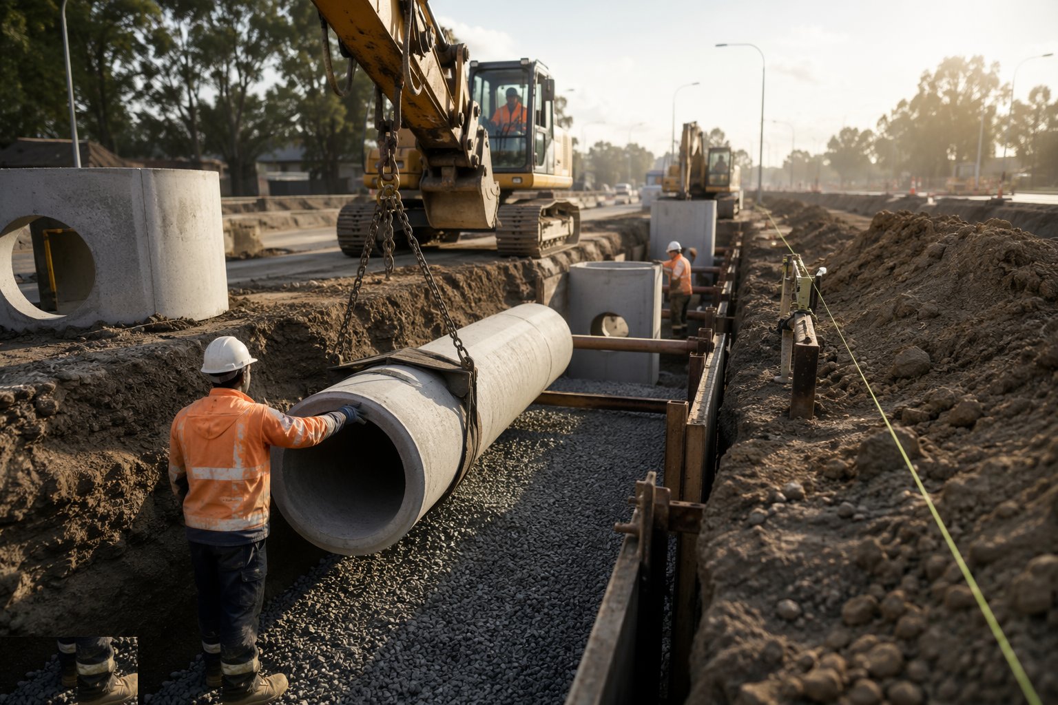
Lay pipes on a compacted granular bed — typically 100 mm — socket uphill, from the downstream end, to laser-set line and level. Joints are home, lubricated and clean; the pipe is bedded and haunched in granular surround compacted at the sides, never dropped onto hard spots. Deflection is checked as you go — an over-deflected flexible pipe has lost its strength.
Step 4: Build the chambers and manholes
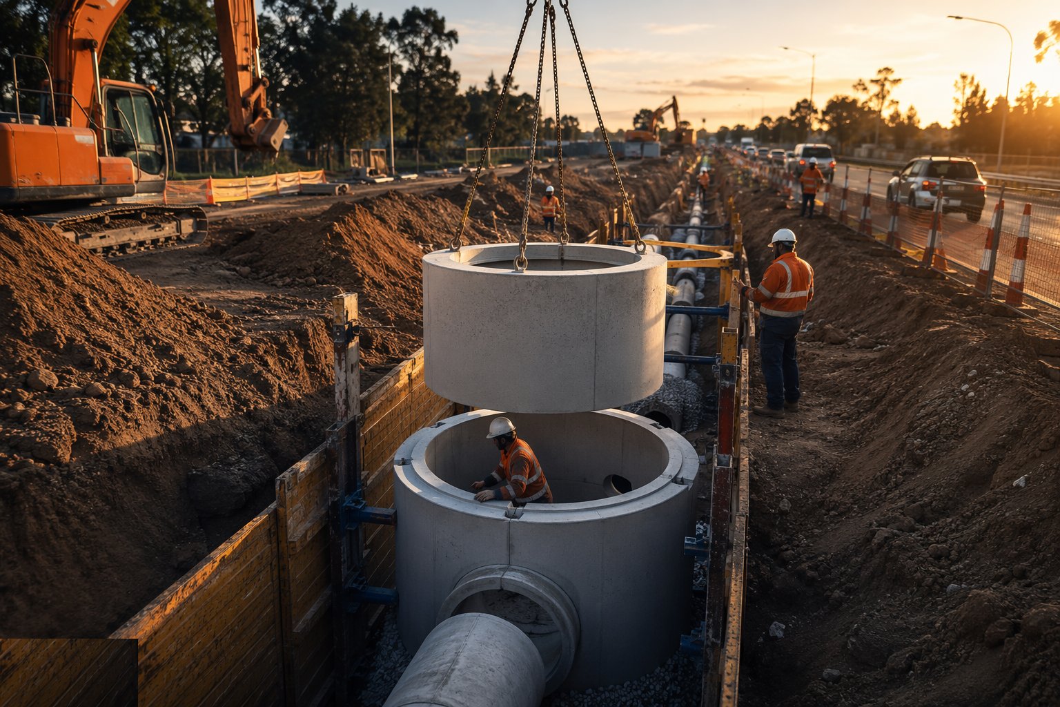
Manholes and inspection chambers go up in precast rings or cast in situ on a base slab, with benching formed to guide flow and channels matched to the pipes. Covers and gratings are set to finished level — on a highway that means matching the future surface course, so frames are often left low and raised at surfacing. Deep chambers are confined spaces and treated as such from day one.
Step 5: Lay ducts and build the utility corridors
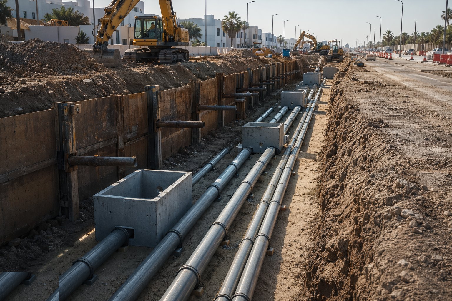
Ducts are laid in straight runs on sand beds with spacers, draw cords installed, and marker tape placed above. Chambers are spaced for the cable pulling lengths, with ducts sealed against silt until the cables come. Crossing ducts under the carriageway go in before the pavement — thrust-bored or open-cut under traffic management where the road is already live.
Step 6: Backfill and compact in layers
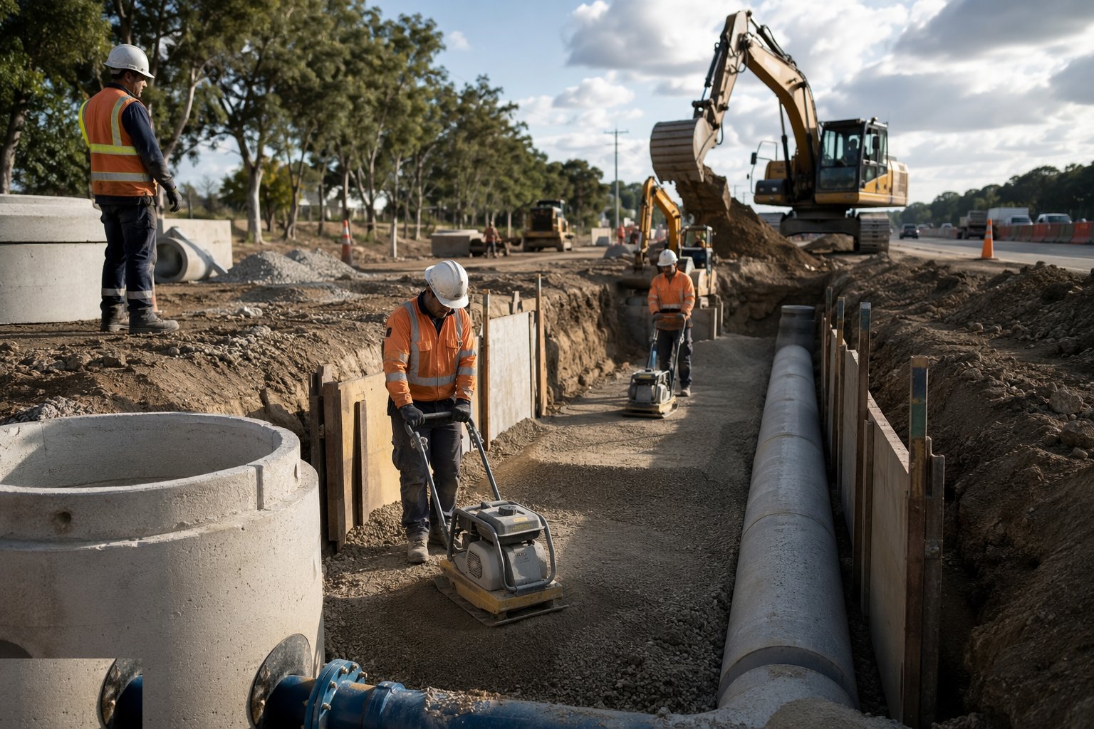
Backfill in compacted layers, protecting the pipe surround with hand compaction above the crown before machines go over. Under pavements, backfill is to Series 600 or the reinstatement specification — a trench that settles leaves a groove in the carriageway and a defect notice. In the live highway, reinstatement is to the Specification for the Reinstatement of Openings in Highways, with its guarantee periods of two years — three for deep openings.
Step 7: Test and survey the completed runs
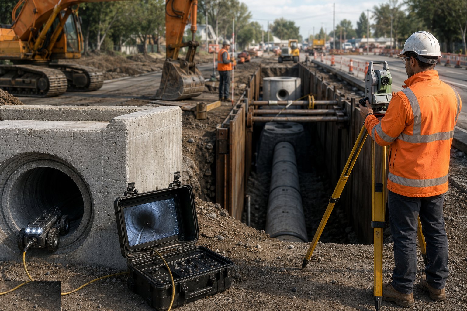
Air or water test the pipes, mandrel-test flexible pipes for deflection, and run a CCTV survey of every adoptable run — the water company will not adopt a sewer it has not seen inside, and the highway authority expects the same discipline. Gullies are rodded and proved. Any infiltration, displacement or debris is rectified before the test is re-run; results go in the handover file.
Step 8: Connect, commission and record as-builts
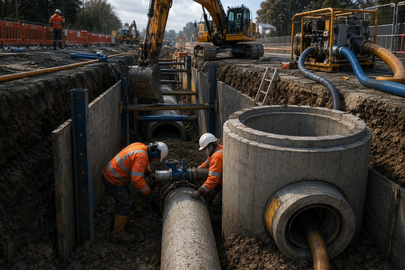
Make the connections to outfalls, existing sewers and live networks — often under the utility's own supervision, sometimes with overpumping while the tie-in is made. Survey every run as built: inverts, chamber positions, duct routes. As-built drawings are a contractual requirement for adoption under Section 104 and for the RTA's as-built certification in Dubai, and they are the only map the next generation will have.
Plant and equipment
- 360° excavators with digging and grading buckets
- Trench boxes, sheets and hydraulic frames for support
- Pipe lasers and grade sheets for line and level
- Laser levels and pipe lasers; mandrels for deflection testing
- Compaction plates and trench rammers
- Wellpoint dewatering sets and submersible pumps
- Thrust-boring or auger-boring rigs for crossings under live roads
- CCTV crawler camera units and air/water test kit
Quality control checks
- Pipe line, level and gradient checked by laser on every length
- Bedding and surround materials to specification, compacted in layers
- Air or water test passed on every run before backfill is accepted
- Mandrel deflection test on flexible pipes
- CCTV survey of adoptable sewers with the report filed for the water company
- Backfill density testing under pavements and reinstatement to the SROH in the highway
- As-built surveys of inverts, chambers and duct routes before covering up
Safety considerations
- No entry to unsupported trenches over 1.2 m; ladder access and edge protection at every open excavation
- Permit to dig with CAT scan — live services are the rule, not the exception, in utility corridors
- Confined space procedures for deep chambers: gas testing, ventilation, rescue arrangements
- Trench spoil and plant kept back from edges; barriers around open excavations beside the public
- Dewatering discharge only to approved outlets with consent
- Live traffic interface where works cross or run beside the carriageway
Common defects
- Pipe laid to a reverse gradient — the laser was set up wrong and nobody checked the inverts
- Settlement over a trench where backfill was dumped, not layered — a groove in the new carriageway
- Chamber benching missing or wrong — a maintenance liability for forty years
- Ducts silted or crushed because they were not sealed or surrounded properly — cables will not pull
- Sewer rejected at adoption CCTV for infiltration or displacement joints
- As-builts left to the end: the duct bank's position is now local folklore
Best suited for
- Buried networks installed before the pavement closes them forever
- Carrier drains, culverts and attenuation serving the whole corridor
- Utility ducts and chambers with capacity left for future services
- Works among live services under permits, trial holes and safe-digging rules
How long does Drainage & Utility Corridors take?
Typical duration: 2–4 weeks per drainage catchment or duct corridor section on a highway scheme; utility diversions run to the undertaker's programme — allow months for HV and telecoms diversions..
Related processes
- Corridor Access & Enabling Works
- Survey Control & Ground Investigation
- Bulk Earthworks — Cuttings & Embankments
- Subgrade Preparation & Capping
- Sub-base & Base Construction
- Asphalt Surfacing — Binder & Surface Course
- Kerbs, Footways & Road Furniture
- Road Markings, Signage & Lighting
- Testing, Commissioning & Asset Handover
- Drainage & Utility Corridors in Bridges & Elevated Structures
- Drainage & Utility Corridors in Tunnels & Underground
- Drainage & Utility Corridors in Rail & Metro
- Roads & Highways sector guide
- Transport Infrastructure group