TRVs & Heating Controls
Thermostatic radiator valves, programmers and smart controls — the small fittings that decide whether a heating system actually works.
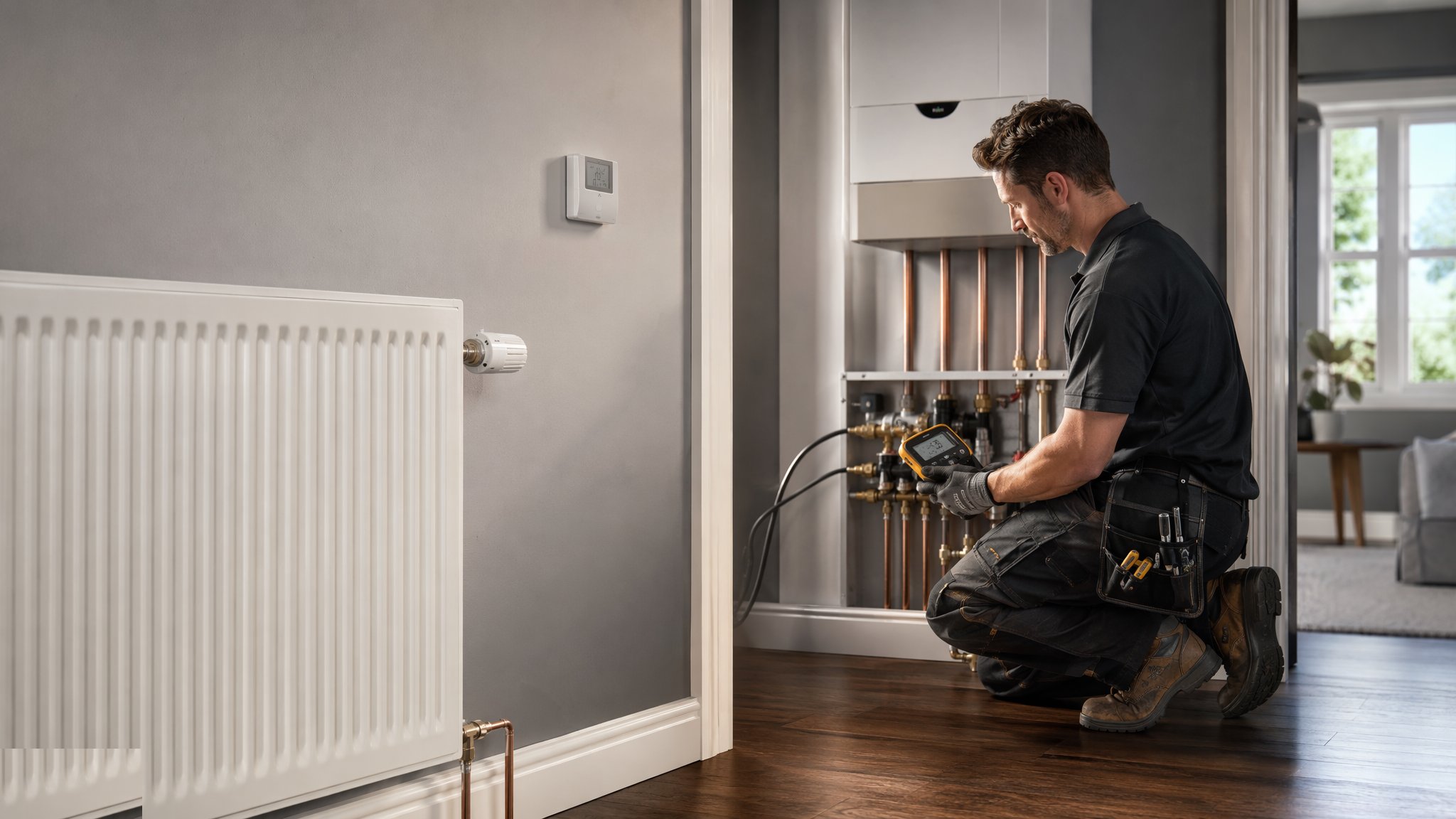
Last updated 2026-07-28 by the BuildPedia Editorial Team.
What is TRVs & Heating Controls?
A heating system without controls is a boiler heating the street through the spare bedroom. The control layer — thermostatic radiator valves on the radiators, a room thermostat or smart stats in the right rooms, a programmer that matches the house's life, and on bigger systems zone valves, weather compensation and balancing — is what turns plant into comfort and fuel bills into reasonable numbers. The TRV is the humble hero: a wax or liquid sensor that throttles the radiator as the room warms, fitted on the flow with the lockshield on the return doing the balancing. It costs little, saves much, and is fitted wrong or never commissioned on a remarkable share of systems.
The UK market is TRV heartland — Part L effectively demands room-by-room control, and the smart-stat wave added learning schedules and zoning to the same bones. In the UAE the heating demand is trivial but the control logic is identical in reverse on the cooling side: zone control, thermostats and balancing decide whether the system works or just runs. Either way, the commissioning — balancing the lockshields, setting the TRVs, proving the controls against the season — is where the performance actually happens.
When and why is TRVs & Heating Controls used?
Controls fit at second fix with the radiators and the wiring, after the plumbing first fix has put the pipes where the valves can reach them. They exist because a boiler or heat pump meeting a single thermostat in the hall overheats half the house and underheats the rest; room-level control fixes comfort and cuts consumption by double digits. They are commissioned — balanced, set and proven — because a TRV left at maximum is a decoration, and a system never balanced delivers all its heat to the nearest radiator.
Types of TRVs & Heating Controls
TRVs & lockshields — the standard set
A thermostatic valve on the flow of each radiator, lockshield on the return for balancing, and the bypass arrangement the boiler needs. The UK default; the valve goes on the flow with its arrow respected, and the one room with the main stat often goes TRV-less by design.
Programmers, stats & smart controls
The system brain: a programmable room thermostat (or smart stats with app zoning and geofencing), the programmer or scheduler, and boiler interlock so the plant only fires when a zone actually calls. Smart TRVs add per-room schedules without re-piping.
Zoned systems & UFH manifolds
Motorised zone valves splitting the house into circuits, or underfloor heating manifolds with their actuators, mixing and per-loop flow gauges — controls that need wiring centres, hydraulic separation thought, and commissioning per loop.
Commercial & tower controls
BMS-linked control of FCUs, radiators and AHUs in offices and tower common parts: schedules, setpoints and frost protection run from the head-end, with local TRVs or thermostatic control in the cellular spaces and the metering that tells the landlord what the system costs.
TRVs & Heating Controls: step by step
Step 1: Design the control strategy
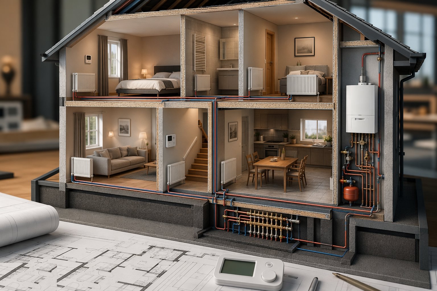
Before a valve is bought: which rooms get TRVs, where the main stat lives (the reference room, not the sunniest), the programmer schedule around the occupants' real life, and the zones where the house splits. On UFH and zoned systems the wiring centre and the hydraulic design are drawn together — controls retrofitted to a system never designed for them behave like it.
Step 2: First fix — pipes and wiring to the right places
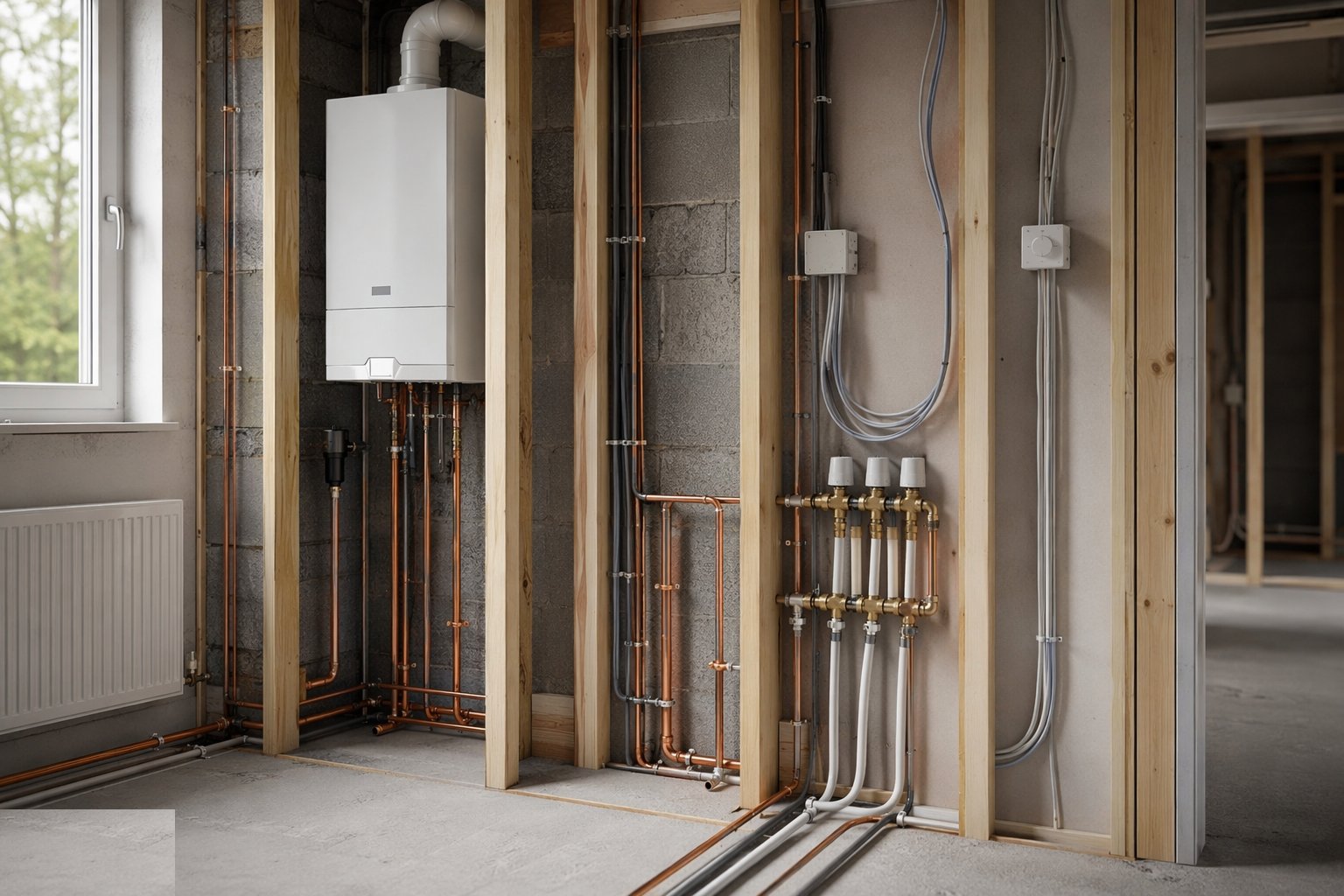
The plumbing first fix puts flow and return where the valves will go, and the control wiring runs with the electrical first fix: stat cables to the right walls, zone valve and wiring centre connections, and the boiler interlock path. Valve orientations are planned now — a TRV body that only fits upside down behind a radiator is a first-fix failure.
Step 3: Fit TRVs and lockshields at second fix
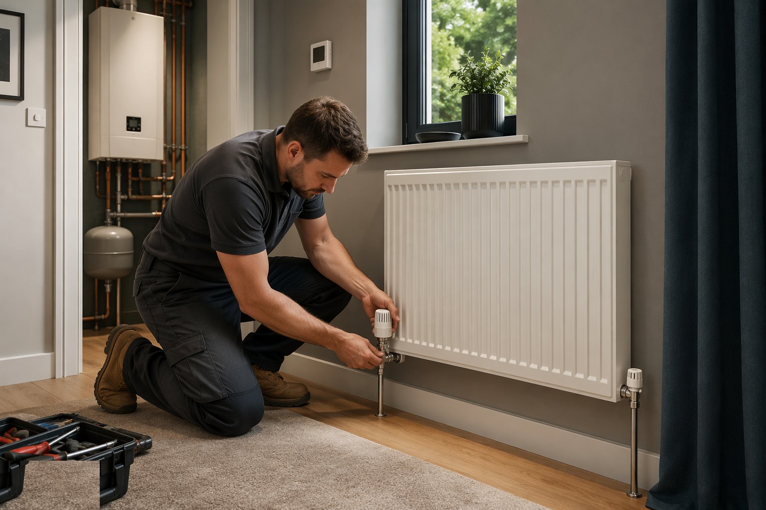
Valves fit at the radiator tails with the flow direction respected, heads accessible and away from curtains and alcoves that would lie to the sensor about the room temperature. Lockshields fit the returns with their caps kept — the balancing settings live on those caps and in the commissioning record.
Step 4: Install stats, programmers and zone hardware
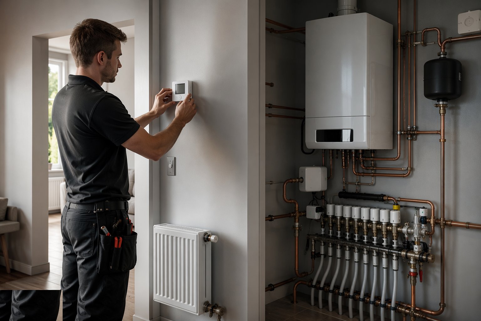
The room stat mounts at 1.5 m on an internal wall away from draughts and heat sources; programmers and smart hubs commission onto their networks; zone valves, actuators and wiring centres wire to the schematic with every connection proven. Smart systems get their accounts, permissions and fail-safes set with the homeowner, not left on installer logins.
Step 5: Balance the system
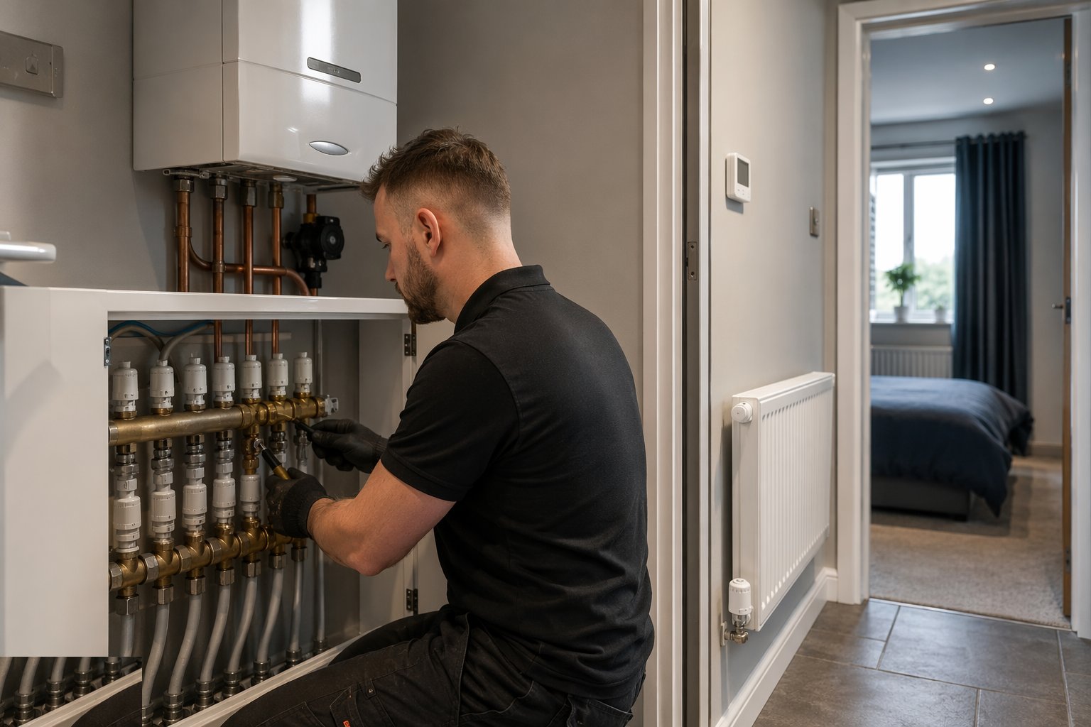
With the system filled and vented, each lockshield is set so every radiator gets its design flow — the far bedroom heats with the hall, not after it. By temperature drop across the radiator or by the modern delta-T method, the figures are recorded radiator by radiator. Balancing is the commissioning step most often skipped and most loudly complained about later.
Step 6: Set the TRVs and the schedules
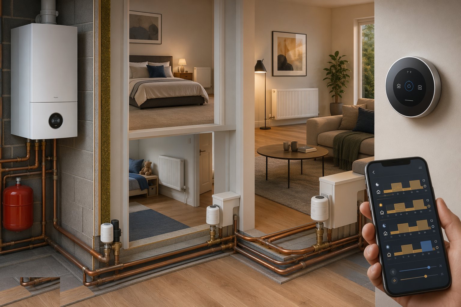
TRV heads set per room use — bedrooms lower, living spaces higher, the reference room per the stat strategy — and the programmer or app schedules set with the occupants: wake, away, evening, sleep. Frost protection and boiler interlock are proven: stat satisfied, boiler off, no ghost firing.
Step 7: Prove the system through a cycle
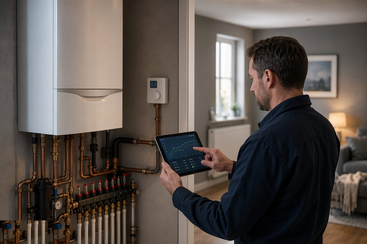
The system runs a full heat-up from cold with the temperatures logged: rooms reach setpoint without overshoot war, the boiler modulates or cycles sensibly, and any UFH loops hold their flow settings. Smart features — zoning, geofencing, weather compensation curves — are demonstrated working, not just present in the app.
Step 8: Hand over — settings, records and the seasonal briefing
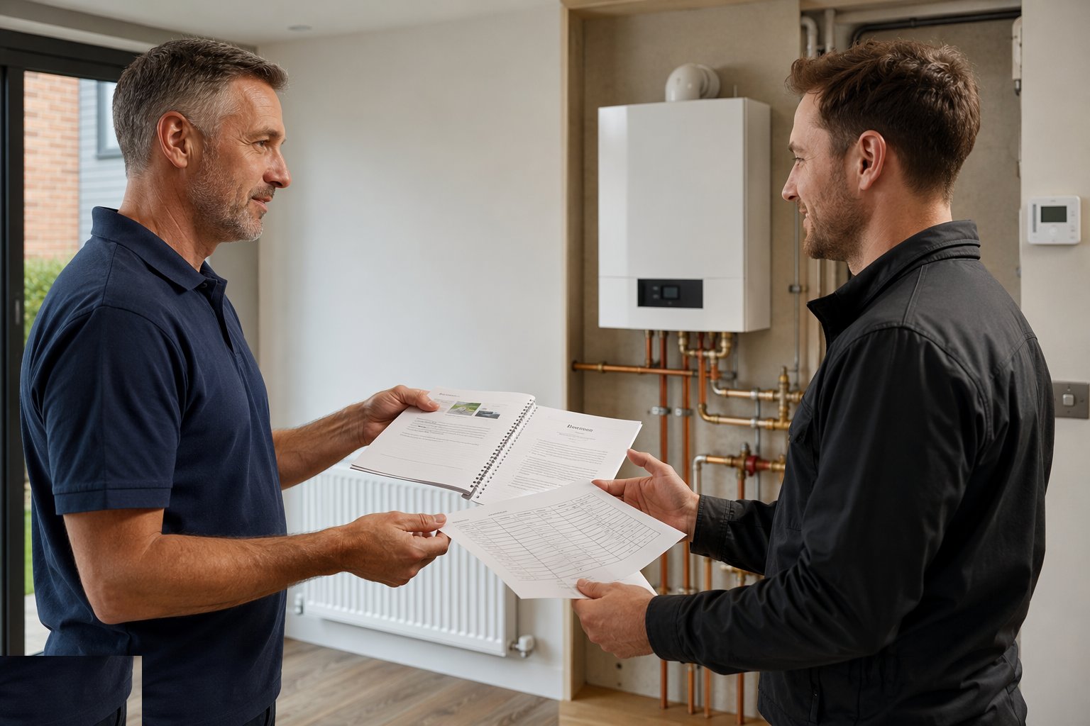
The handover covers the balancing record, the TRV settings per room, the control manual in plain language, and the seasonal advice: what to touch when winter arrives, what the TRV numbers mean, and why the lockshield caps are not radiator ornaments. On commercial systems the BMS graphics, setpoints and alarms hand over with witnessed point-to-point records.
Plant and equipment
- Valve and fitting kit with the correct threads and adaptors
- Manometers and thermometers for delta-T balancing
- Wiring kit and multimeter for control circuits
- Smart hub commissioning devices and network access
- Flow gauges for UFH manifolds
- Label kit for valves, zones and wiring centres
- Commissioning record sheets
Quality control checks
- Control strategy signed off against the system design before install
- Valve orientation and sensor positions checked per radiator
- Wiring proven point to point against the schematic
- Balancing figures recorded per radiator or loop
- Interlock and frost protection function-tested
- Settings schedule (TRVs, stats, programmes) recorded at handover
Safety considerations
- Hot system precautions on filling, venting and balancing
- Electrical isolation for wiring centre and boiler connections
- Scalding protection where flow temperatures run high
- COSHH on inhibitors and cleaners dosed during commissioning
- Manual handling minimal; access care in airing cupboards and voids
- Pressure awareness on sealed systems during valve work
Common defects
- TRVs behind curtains or above radiators sensing their own weather
- Nearest radiator roasting, far one cold — never balanced
- Main stat in the hall with a TRV fighting it in the same room
- Boiler firing with no zone calling — missing interlock
- Smart controls on the installer's account, homeowner locked out
- Lockshield settings lost: caps binned, no record, rebalance by folklore
Best suited for
- UK wet heating systems — Part L room control done properly
- Radiator upgrades and boiler/heat-pump swaps needing rebalancing
- Zoned and UFH systems where per-loop commissioning is the job
- Commercial common parts with BMS control and metering
- Cooling-side zone control in the Gulf — same logic, opposite season
How long does TRVs & Heating Controls take?
Typical duration: A house set: a day to fit, half a day to balance and commission properly. That half day is the difference between a system and a complaint..
Related processes
- Windows & Doors Installation
- Flooring & Floor Finishes
- Private Swimming Pool Construction
- CCTV & Security Systems Installation
- Soft Landscaping & Gardens (Homes & Villas)
- Carpentry — First & Second Fix
- Brick Wall Construction
- Block Wall Construction
- Concrete Structural Walls
- Damp Proofing — DPC, DPM and Cavity Trays
- Firestopping and Passive Fire Protection
- Chasing & First-Fix Cutting for Services
- MEP — Plumbing (First & Second Fix)
- MEP — Electrical (First & Second Fix)
- Ventilation & Air Conditioning
- Below-Ground Drainage Installation
- Sanitary Installation
- TRVs & Heating Controls in Residential & Housing
- TRVs & Heating Controls in Commercial & Workplace
- Building Trades & Methods sector guide
- Buildings group