Ventilation & Air Conditioning
Split systems, VRF, ducted ventilation and district cooling interfaces — moving and conditioning air by build type and climate.
Last updated 2026-07-28 by the BuildPedia Editorial Team.
What is Ventilation & Air Conditioning?
In the UK, ventilation is the compliance story — Part F rates, extract fans, trickle vents and, increasingly, whole-house MVHR — and cooling is the optional extra. In the UAE that is inverted: air conditioning is life support, designed for 48 °C ambient, and the question is which system — split units on a villa, VRF on a mid-rise, chilled water from the district cooling plant on a tower. Both markets share the same physics and the same failure modes: undersized units that never quite cope, ductwork that leaks its conditioned air into the void, condensate drains that stain the facade, and commissioning skipped because the system "seems to blow cold".
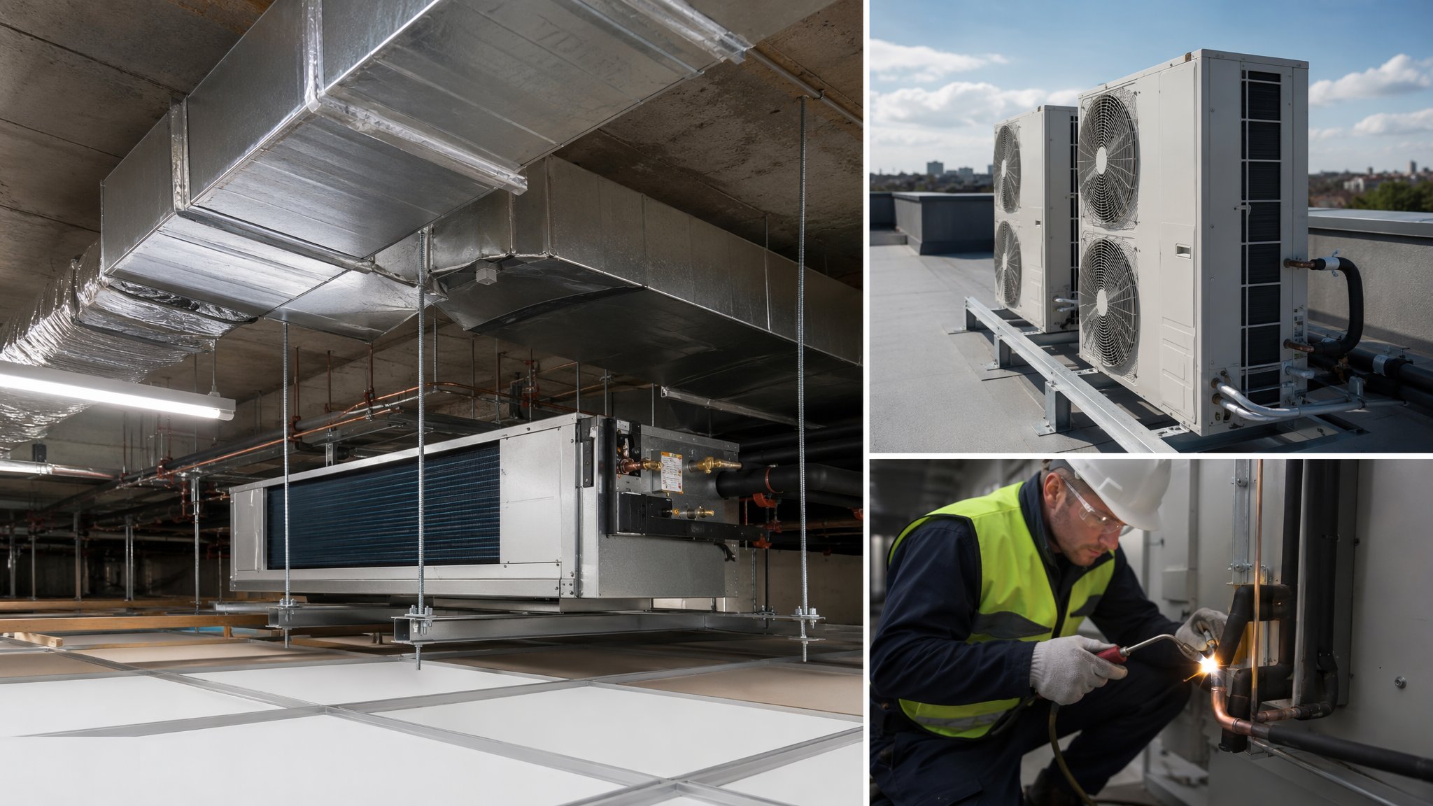
The trade spans refrigeration pipework (a brazed, pressure-tested, evacuated specialist operation), sheet-metal ductwork, grilles and diffusers, controls and the condensate drainage nobody thinks about until it drips on a finished ceiling. On towers add the plant interface: fan-coil units fed from the district cooling supply (Empower or Tabreed in Dubai) with energy transfer stations, BTU metering and water-side balancing.
When and why is Ventilation & Air Conditioning used?
First fix installs the heavy and hidden elements — outdoor unit bases and refrigerant routes, ductwork in voids, fan-coil units, condensate drains — while the ceiling is open, because a duct you cannot fit at first fix becomes a bulkhead everyone hates at second fix. Second fix fits the indoor units, grilles, controls and commissioning after decoration. The system exists to meet the indoor environment the regs and the climate demand; it is commissioned because an unbalanced, uncharged, unmeasured system is a guess with a warranty.
Types of Ventilation & Air Conditioning
Homes & villas — split systems
Wall, ducted or cassette indoor units fed from outdoor condensers, common on UAE villas and increasingly UK homes with air-to-air heat pumps. Refrigerant pipework in insulated pairs, condensate to drain, and controls per room. UK villas of the traditional sort run MVHR instead: a heat-recovery unit with supply and extract ducts to every room.
Residential & office mid-rise — VRF
Variable refrigerant flow: one outdoor bank serving many indoor units with individual control, refrigerant distribution boxes in the voids, and a central controller. Efficient and flexible, but every brazed joint is a potential leak in a sealed system holding kilograms of refrigerant — installation and pressure test discipline is everything.
Towers — chilled water & district cooling
District cooling (or a plant-room chiller) supplies chilled water to an energy transfer station per building, then to fan-coil units per apartment or air-handling units per office floor. Water-side balancing, BTU metering for billing, and DCD-compliant smoke control interfaces close the design.
Ventilation-only — extract & MVHR
UK Part F compliance: intermittent or continuous extract from wet rooms, whole-house MVHR with summer bypass, fire dampers where ducts cross compartment lines, and background ventilators sized to the airtightness the building actually achieved — which is why commissioning waits for the air test result.
Ventilation & Air Conditioning: step by step
Step 1: Confirm loads, layout and routes
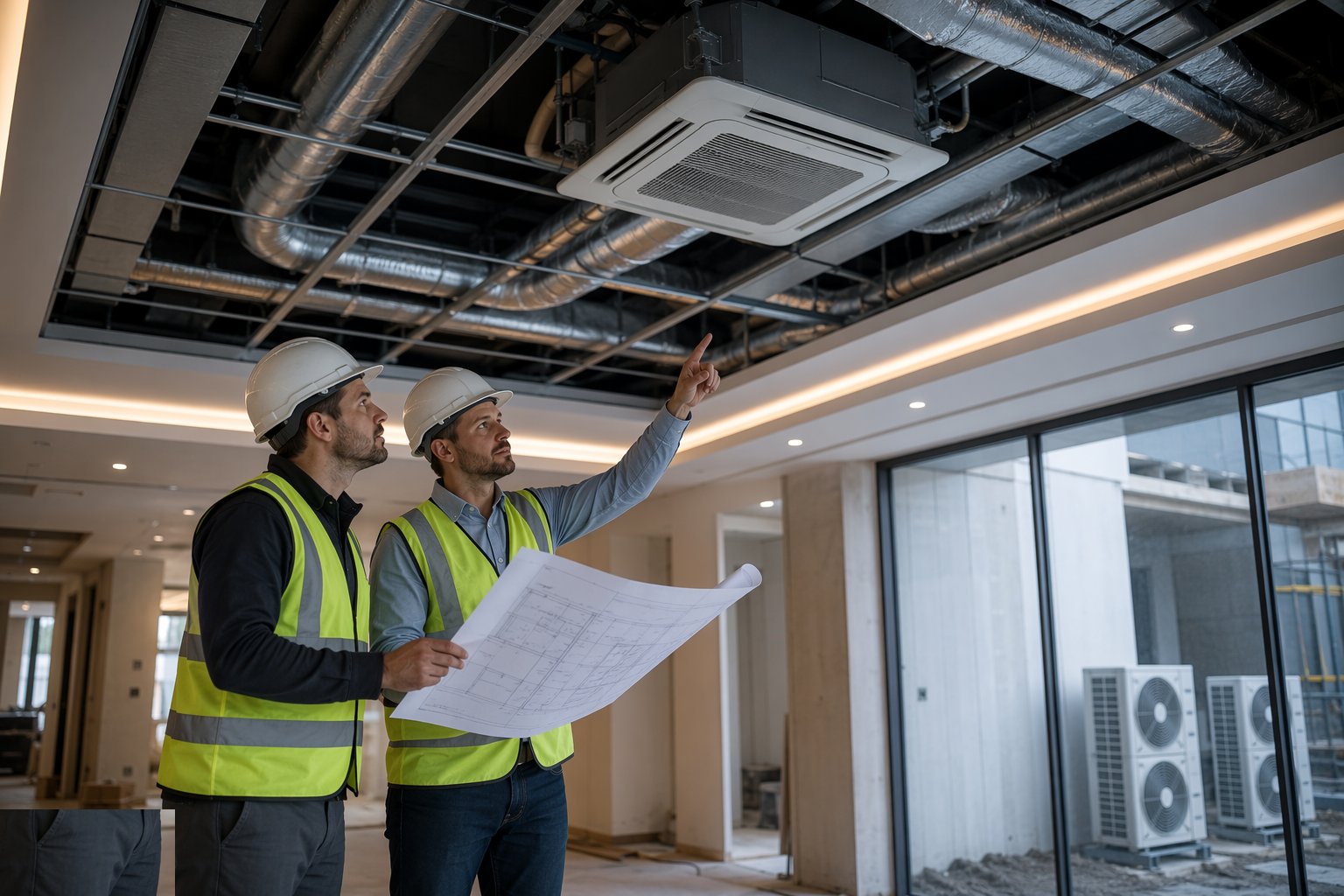
The heat-load or ventilation calculation fixes unit sizes and air volumes; the layout fixes indoor unit, grille and diffuser positions against the ceiling design and the lighting. Refrigerant pipe routes, duct sizes and condensate falls are coordinated with the other services in the void — the drawing that wins the coordination meeting is the one with the fewest bends.
Step 2: Install outdoor plant and bases
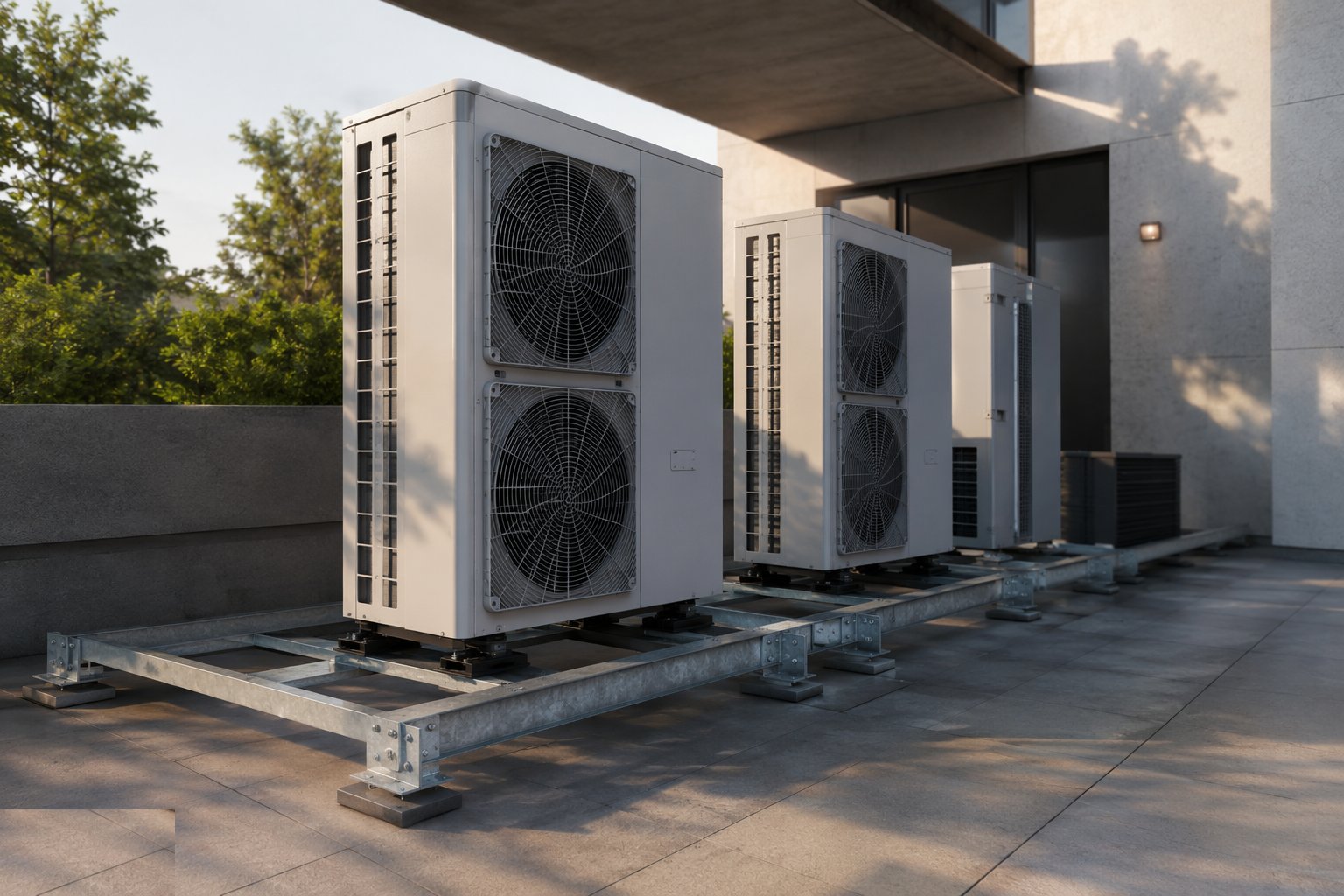
Condensers, heat-pump units and roof plant land on engineered bases or frames with vibration isolation, service access on all sides, and airflow that is not recirculating into itself. On UAE roofs that also means shade where possible, corrosion protection in coastal air, and fixings rated for the wind zone.
Step 3: Run refrigerant pipework and condensate — first fix
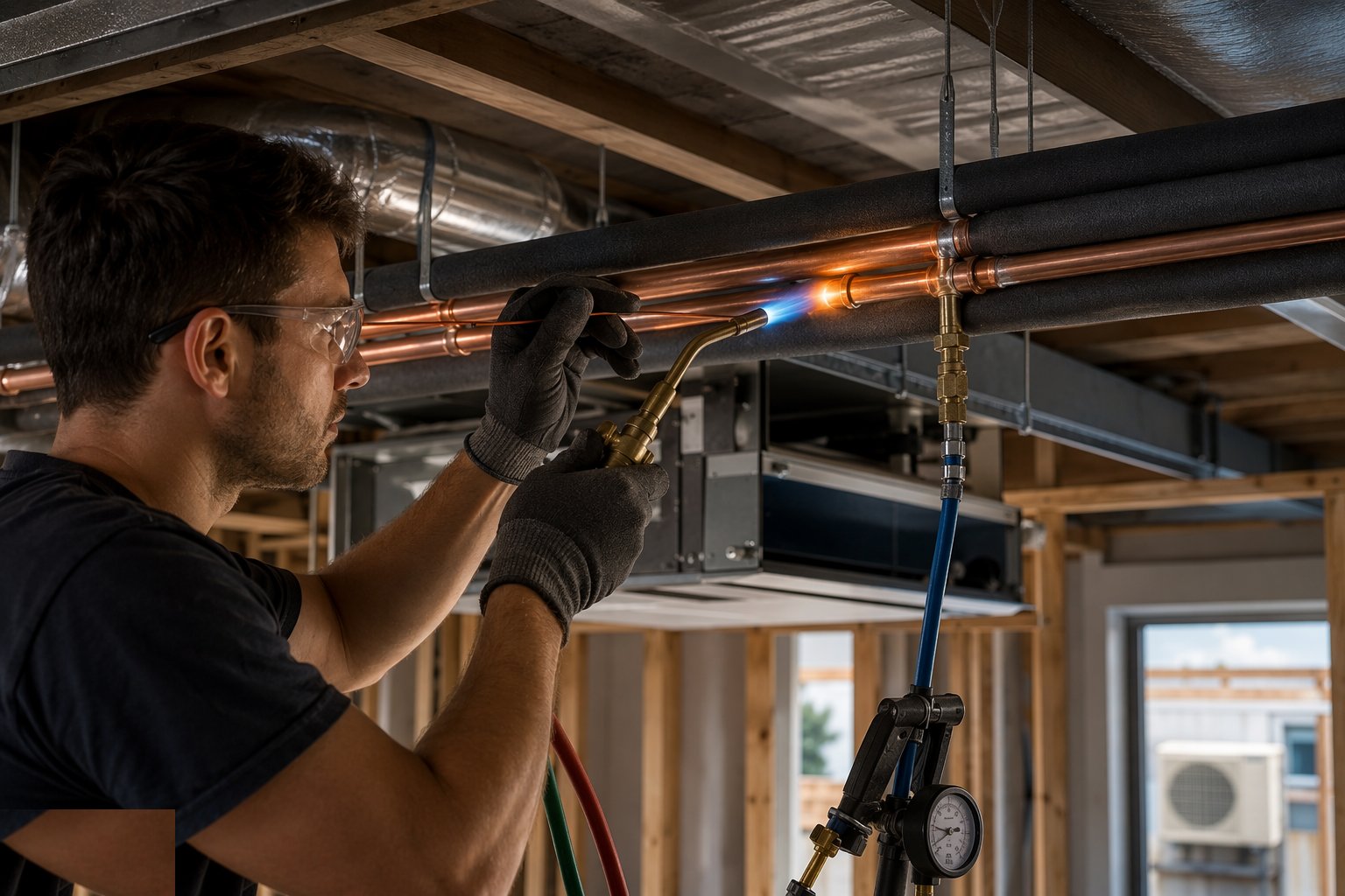
Refrigerant pairs are brazed with nitrogen purge flowing (no purge, and oxide scale waits in the pipe to kill the compressor), insulated continuously, and pressure tested with nitrogen to the manufacturer's figure before evacuation. Condensate drains run at fall to a real drain with traps and access — never into a soakaway of hope above a finished ceiling.
Step 4: Install ductwork, dampers and FCUs
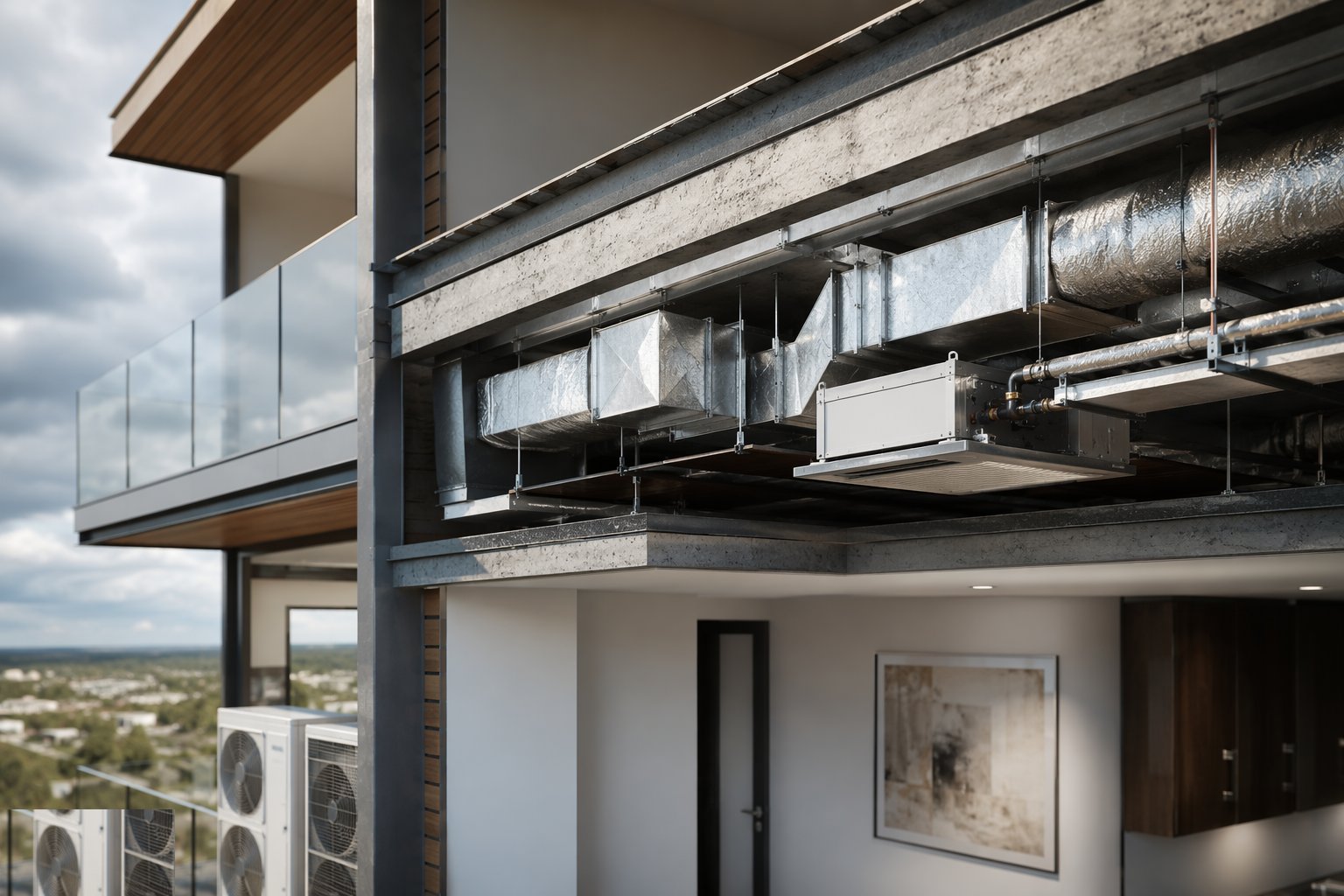
Sheet-metal or rigid ductwork goes in supported, sealed to its leakage class, insulated where it crosses unconditioned space, with fire and smoke dampers at compartment lines wired to the fire strategy. Fan-coil and MVHR units hang level with flexible connections, filter access and valve sets oriented for the person who will one day balance them.
Step 5: Evacuate, charge and connect controls
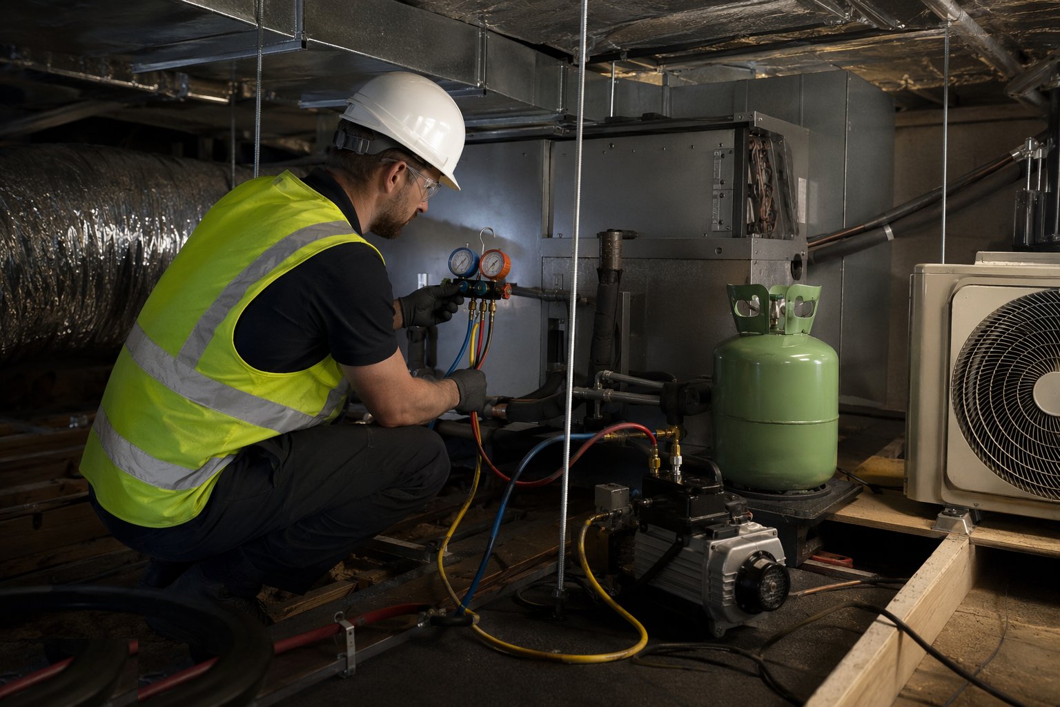
Refrigerant systems are evacuated to the specified vacuum and held, then charged by weight to the manufacturer's figure — not "topped up by feel". Controls are wired and addressed: room stats, central controllers, BMS points and the fire alarm interface that drops the system on smoke. Every sensor is checked against reality, not just the drawing.
Step 6: Second fix — indoor units, grilles and diffusers
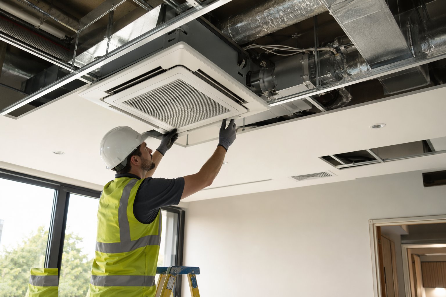
After decoration: indoor units mount level and condensate-tested, grilles and diffusers fit the ceiling grid with throw patterns checked against the room use, and MVHR supply/extract valves are set roughly to design before balancing. Escutcheons and finishes are the bits the client sees — they get the same care as the pipework they hide.
Step 7: Air and water balancing
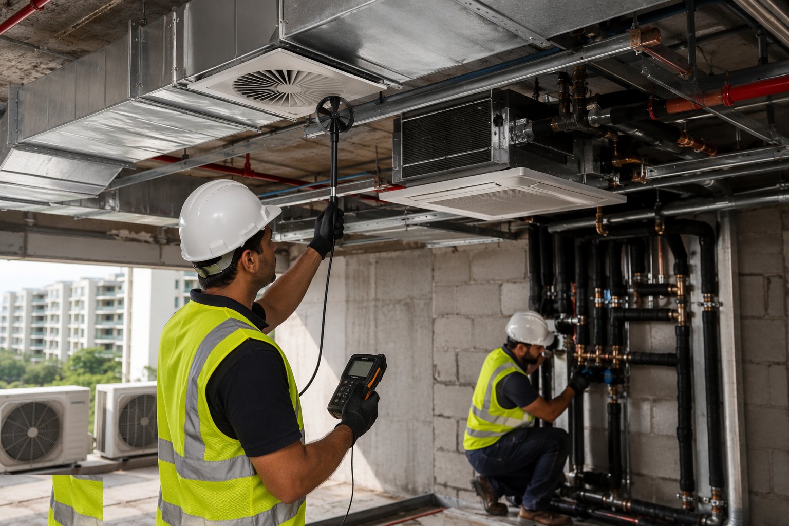
Air volumes are measured at terminals and set to design with the dampers; water-side, the balancing valves are set so every FCU gets its design flow. The figures go on the commissioning schedule terminal by terminal. A system that "feels fine" in the plant room and starves the end room is a failed balance, however cold the corridor is.
Step 8: Commission, witness and hand over

Full commissioning: refrigerant pressures and temperatures against the chart, airflow totals against Part F or the design, controls sequences witnessed, BTU meters verified where district cooling bills on them, and DCD smoke-control interfaces tested where applicable. The O&M pack — filters, access, seasonal changeover, F-Gas log where refrigerant applies — goes to the operator with a walkthrough, not just a folder.
Plant and equipment
- Brazing kit with nitrogen purge regulators
- Vacuum pumps, micron gauges and refrigerant charging scales
- Nitrogen pressure test rigs and leak detectors
- Ductwork: folders, seamers, lifts and support systems
- Balometer and anemometers for air measurement
- Manometers and ultrasonic flow meters for water-side balancing
- Recovery machines and cylinders for refrigerant handling
Quality control checks
- F-Gas certified installers and refrigerant handling records
- Braze joint inspection and nitrogen pressure test certificates
- Vacuum hold records before charging; charge by weight logged
- Duct leakage test results to the specified class
- Damper locations and fire-strategy interfaces checked and photographed
- Commissioning schedules: air volumes, flows, pressures and temperatures vs design
Safety considerations
- Refrigerants: asphyxiation in confined spaces, pressure systems, PPE for charging
- Hot works permit for brazing with fire watch in voids
- Roof work: edge protection, fragile-surface controls, heat stress in UAE summers
- Heavy lifts of outdoor units and AHUs under a lift plan
- Electrical isolation of supplies during installation and commissioning
- COSHH on cleaners, oils and treatment chemicals
Common defects
- Refrigerant leaks at unpurged brazed joints — the slow death by top-up
- Condensate drips through ceilings from flat or trapped drains
- Duct leakage dumping conditioned air into the void — measured, or guessed
- Rooms starved of air where balancing was skipped after ceiling changes
- Outdoor units recirculating on crowded roofs — capacity that never arrives
- Controls addressed wrong: the stat in room 5 switching the unit in room 7
Best suited for
- UAE villas and apartments — splits and VRF as the default climate control
- Towers on district cooling with FCUs and BTU metering
- UK homes meeting Part F with MVHR on airtight builds
- Offices needing zoned, metered comfort per tenant
- Any sealed, insulated building where ventilation must be designed, not hoped for
How long does Ventilation & Air Conditioning take?
Typical duration: A villa split system: 2–4 days. A VRF floor: 1–2 weeks per floor cycle. Commissioning and balancing: days to weeks, and it only counts when witnessed and recorded..
Related processes
- Firestopping and Passive Fire Protection
- Chasing & First-Fix Cutting for Services
- MEP — Plumbing (First & Second Fix)
- MEP — Electrical (First & Second Fix)
- Below-Ground Drainage Installation
- Sanitary Installation
- Windows & Doors Installation
- Flooring & Floor Finishes
- Private Swimming Pool Construction
- CCTV & Security Systems Installation
- TRVs & Heating Controls
- Soft Landscaping & Gardens (Homes & Villas)
- Brick Wall Construction
- Block Wall Construction
- Concrete Structural Walls
- Damp Proofing — DPC, DPM and Cavity Trays
- Carpentry — First & Second Fix
- Ventilation & Air Conditioning in Residential & Housing
- Ventilation & Air Conditioning in Commercial & Workplace
- Ventilation & Air Conditioning in Healthcare
- Building Trades & Methods sector guide
- Buildings group